
Development of a Standing Assistance Walker for a Patient with Low
Level of Care
Daisuke Chugo
1
, Shohei Kawazoe
1
, Sho Yokota
2
, Hiroshi Hashimoto
3
, Takahiro Katayama
4
,
Yasuhide Mizuta
4
and Atsushi Kojina
4
1
School of Science and Technology, Kwansei Gakuin University, Sanda, Hyogo, Japan
2
Department of Mechanical Engineering, Toyo University, Kawagoe, Saitama, Japan
3
Advanced Institute of Industrial Technology, Shinagawa, Tokyo, Japan
4
Service Robot Division, RT.WORKS CO., LTD, Osaka, Japan
Keywords: Standing Assistance, Active Walker, Patient with Low Level of Care.
Abstract: This paper proposes a novel low cost robotic walker with standing assistance function. Our system focuses
on domestic use for elderly people who is low level of care and need nursing in their day-to-day lives.
Usually, these patients require a partial standing assistance only when they need it, not a full assistance
during standing motion such as a hanging by the lift. The widely and easily use of such assistance in daily
life will be successful in ensuring safety and providing an inexpensive manufacturing cost. These two
opposed requirements have been realized with our developed robotic walker. Our key ideas are two topics.
First is proposal of a mechanical design with minimum and smaller actuators. Proposed system uses a gas
spring which helps the up/down actuator and our system assists the patient with wheel actuators on a
powered walker for stabilizing its user as well as for lifting up the user. Second is assistance procedure
which leads the patient to suitable posture by the force guidance and voice instruction. We investigate what
factor enables the patient to stand up safety by preliminary experiment. The performance of our proposed
system is verified through experiments using our prototype with elderly and handicapped subjects.
1 INTRODUCTION
Activities such as standing, walking, and sitting may
be the most serious and important activities in the
day-to-day lives of elderly people as they lack
physical strength (Alexander et al., 1999; Hughes et
al., 1996). However, assisting elderly individuals in
these tasks can be difficult for caregivers and can be
a primary source of the lumbago that many of them
experience. Thus, developing a caregiving robot
capable of assisting the elderly when they stand,
walk, and sit is important, and many such devices
have been developed and reported in previous
studies (Nagai et al., 2003; Funakubo et al., 2001).
In Japan, elderly people requiring assistance in
their daily lives are classified into five different care
levels (Cabinet Office, Government of Japan, 2016),
where care level 1 is minor and care level 5
represents a serious condition such as bedridden life.
Elderly people within care level 2 or less are more
than 60% and voluntarily body movement in normal
daily-life activities is important in order to keep their
physical strength, and thereby preventing to become
worse care level (Hirvensalo et al., 2000). They have
difficulty in standing, walking or sitting on their own
but are otherwise able to perform routine activities if
partial assistance only for these motions is provided.
This paper calls these situations as low level of care.
In many previous researches, devices that can aid
in such activities are developed (Munro et al., 1998),
but these are designed for care houses and hospitals
because their motivation is reducing the caregivers’
burden. On the other hand, the assistive robot for
low level of care people should be widely used in
their homes. For realizing them, the robot is required
to be practical and low cost. The robot should be
compact for easy use because standing, walking and
sitting motion will be done in narrow space in daily-
life activities. Furthermore, the robot should have
enough assistive performance and fail-safe design
providing an inexpensive manufacturing cost.
However, no such robots have yet been developed.
In our previous studies, we developed an
assistive robot to continuously aid patients with
activities such as standing, walking, and sitting
(Chugo et al., 2015; Chugo et al., 2012). The robot
142
Chugo, D., Kawazoe, S., Yokota, S., Hashimoto, H., Katayama, T., Mizuta, Y. and Kojina, A.
Development of a Standing Assistance Walker for a Patient with Low Level of Care.
DOI: 10.5220/0006469501420153
In Proceedings of the 14th International Conference on Informatics in Control, Automation and Robotics (ICINCO 2017) - Volume 2, pages 142-153
ISBN: Not Available
Copyright © 2017 by SCITEPRESS – Science and Technology Publications, Lda. All rights reserved

was based on a walker (a popular assistance device
for elderly people to use in normal daily life) and
had a manipulator with three degrees of freedom
(DOF) to assist patients in standing. We designed
the robotic walker for realizing enough performance
in standing, walking and sitting assistance with
safely, but however, we did not consider its
manufacturaing cost. Its body size was too big for a
typical toilet room in Japan, therefore, it was not
practical in home usage. Furthermore, this system
used many actuators and high-precision sensors, thus,
its cost was too expensive and not acceptable for
home usage of the patient who is low level of care.
For realizing the assistive robot which the many
elderly people can use in their daily-life activities,
the robot should practical and low cost, and of
course should have enough assistance performance.
Therefore, this paper present a novel standing
assistance walker.
For relazing practical robot, we mainly describe
two key topics. First is proposal of a mechanical
design with minimum and smaller actuators.
Proposed system can lift the patient’s body with a
smaller actuator force by combination of a linear
actuator and a gas spring. A gas spring generates
upper direction force when it lifts up. On the other
hand, it stores upper direction force from the
patient’s body weight when it takes down.
Furthermore, developed system enables standing
assistance with only one linear actuator for lifting up
the patient’s body by using wheel actuators on a
powered walker for stabilizing its user.
Second topic is proposal of assistance procedure
which leads the patient to suitable posture by the
force guidance and voice instruction. For realizing
safety standing assistance, the subject is required to
take a stable posture in standing with the robot.
However, it is difficult to guide the motion of the
patient because the assistance for the low level of
care should fir the patient motion based on his/her
will, should not assist all necessary force for doing a
standing motion. Thus, we investigate what factor is
useful to guide the patient’s motion by preliminary
experiment and with this result, this paper proposes
a standing assistance procedure with force guidance
and voice instruction.
The rest of this study is organized as follows:
section 2 explains the configuration of the proposed
system, section 3 describes the assistance procedures,
section 4 describes a practical experiment with
elderly and handicapped people, and section 5
concludes the study.
2 MECHANICAL DESIGN
PROPOSAL WITH MINIMUM
AND SMALLER ACTUATORS
2.1 Required Condition
2.1.1 Required Assistance Function
As mentioned in the Introduction, elderly people
who is low level of care can be considered to be the
main audience of our assistance robot. The
characteristics of these people are follows (Cabinet
Office, Government of Japan, 2016);
The patient has dexterity to take suitable
posture if physical load is small.
The patient can maintain his/her body balance
by grasping the handle on the assistive device.
In other word, he/she has enough force to
grasp it.
The patient requires force assistance for
reducing physical load when he/she lifts up
his/her trunk in standing.
The patient requires assistance for keeping its
body balance during standing, walking and
sitting assistance.
From these conditions, the assistive robot should
have 2DOF minimally, one is up/down direction for
lifting the patient’ body and the other is
forward/backward direction for keeping his/her body
stability. We do not consider the right/left direction
because we can approximate human standing motion
based on the movement on a 2D plane (Nuzik et al.,
1986).
2.1.2 Required Condition for Practical
Usage
Since the proposed walker is small and mobile, it
can be used in any situation in users’ homes. In
typical scenario, if a patient would like to go to the
toilet room from his/her bed via the corridor, he/she
can stand up with the assistance of the walker, walk
through the corridor without scratching the wall,
enter the bathroom, turn around into the sitting
position, and sit down with the device’s assistance.
In this scenario, the narrowest room in Japanese
typical home is a toilet room. A typical toilet door
with a standard width is 600mm (JIS - Japan
Industrial Standard – 1526:1997) and in the toilet
room, the width is 800mm minimally. Therefore, for
using the robot in daily-life activities, the robot
should have the following specifications.
The robot can pass the entrance with 600mm
width.
Development of a Standing Assistance Walker for a Patient with Low Level of Care
143
The robot can rotate with its patient in the area
with 800mm circle.
The robot can approach a chair, a bed and a
toilet enough which enable the sitting patient
to use its standing assistance.
The robot can pass the small steps between the
room and corridor floor. Usually, its height is
within 20mm in the typical Japanese house.
2.2 Developed Robot
2.2.1 System Overview
Considering these conditions in section 2.1.2, we
propose the assistive robot as Fig. 1. Our robot
consists of a powered walker and a standing support
manipulator, which moves the user in an upward
direction so as to be lifted. A standing assistance
manipulator has 1 DOF (up/down direction) which is
generated by a linear actuator and a gas spring (see
section 2.2.2). In standing, our robot assists the
patient cooperating with a standing assistance
manipulator and wheel actuator. (see section 2.2.3)
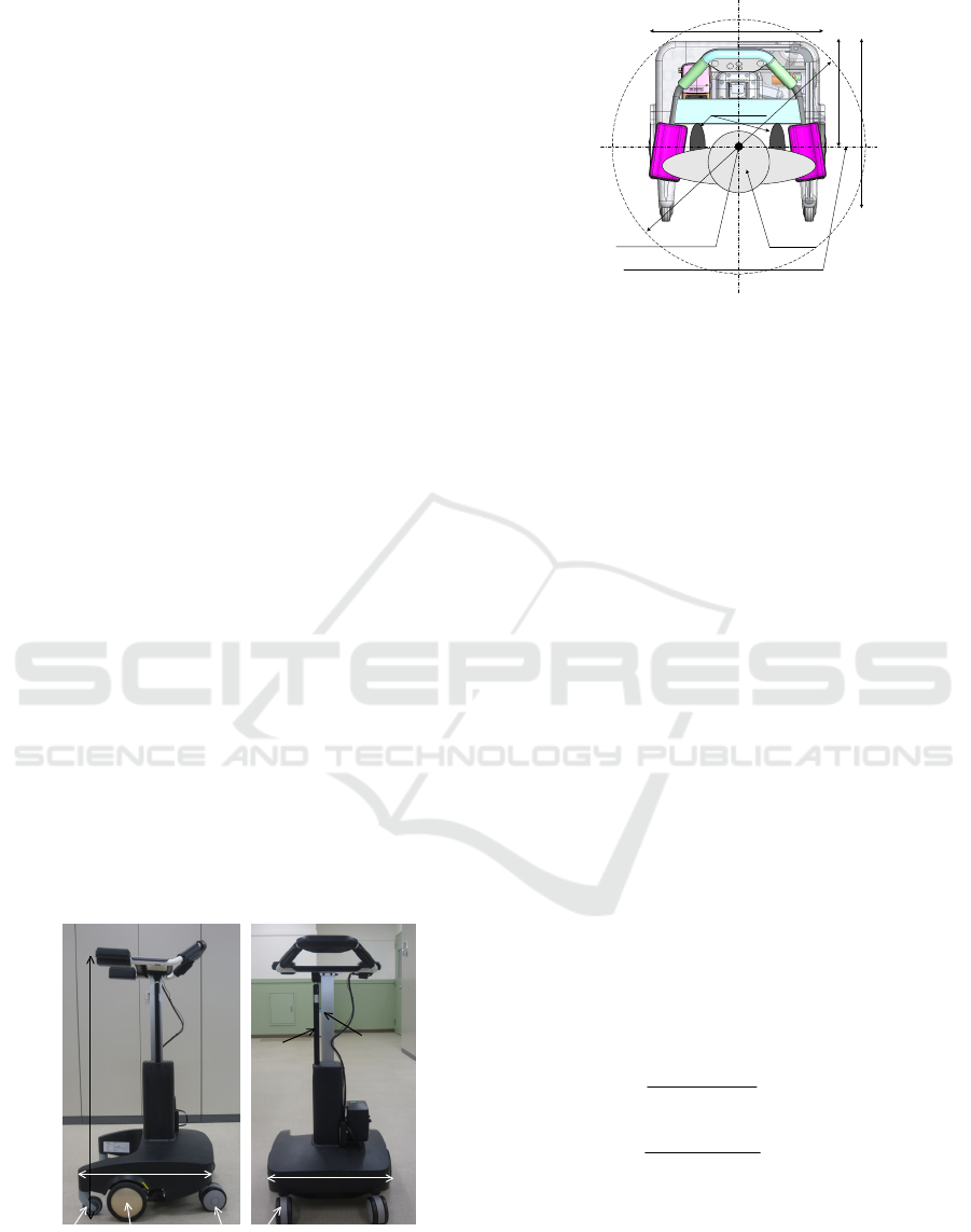
Fig. 2 shows a top view of our robot. Its width is
540mm and can pass easily a typical entrance in the
patient’s home. Our robot has two actuated wheels
in each side. Their axle is same position as the foot
center of its patient and he/she can turn easily within
the circle which diameter is 800mm.
As Fig. 1(b), our robot uses large casters at front
position for increasing the mobile performance on
the non-flat ground. Its diameter is 120mm and it
can pass easily the 20mm height step. On the other
hand, our robot uses small casters at the rear position
for preventing the conflict between the caster and
objects as legs of the chair which its patient sits on.
540mm
Gas Spring
Linear
Actuator
965mm
500mm
Actuated Wheel
Front Caster
Rear Caster
(a) Side view (b) Front view
Figure 1: Our developed robot for standing assistance.
540mm
500mm
340mm
7
9
0
m
m
UserRotation Center
Foot Position
Axle Position of Actuated Wheels
Figure 2: Top view and turning radius of our robot.
2.2.2 Standing Manipulator
A standing manipulator lifts up the patient body
directly and its load tends to be large. Generally for
this purpose, a high powered actuator is suitable,
however, its cost is expensive and there is its
malfunction risk. A smaller actuator with high
reduction gear is useful choice, however, maximum
lifting velocity will be reduced and the robot cannot
lift up the patient by a required velocity.
Thus, this study proposes a novel mechanism
combing a linear actuator and a gas spring as Fig.
1(b). A gas spring can output force almost constant
during its stroke, therefore, it helps the actuator
when the standing manipulator lifts the patient. On
the other hand, when a gas spring shrinks, it requires
down direction force. Usually, in this situation, the
standing manipulator assists in sitting, and a gas
spring shrinks by the body weight of its patient.
Therefore, this device is useful for this purpose and
furthermore, a gas spring is widely used and its cost
is inexpensive.
Generally, a gas spring generates the force
l
f
when it extends as (1), and it requires the external
force
u
f
when it shrinks as (2) as Fig. 3. Because of
its internal resistance
r
f
,
u
f
is larger than
l
f
as (3).
max
minmax
l
stroke
ll
l
fy
y
ff
f +
−
−=
(1)
max
minmax
u
stroke
uu
u
fy
y
ff
f +
−
−=
(2)
rlu
fff +=
(3)
where
y
is the manipulator position and
stroke
y
is its
stroke.
()
uorlif
i
=,
max
is maximum force which
the gas spring can generate and usually, it can
ICINCO 2017 - 14th International Conference on Informatics in Control, Automation and Robotics
144
generate at lowest position
min
y
.
()
uorlif
i
=,
min
is its minimum force at highest position
max
y
.
If the subject applies the maximum load
max
f
to
the robot at
lift
y
when it assists in standing, the
following conditions should be fulfilled.
The total output by the linear actuator and the
gas spring is larger than the maximum load as
(4) when the robot assists to lift up the patient.
For shrinking the manipulator without the body
weight of the patient, the output of linear
actuator is larger than the maximum force
which the gas spring requires to shrink as (5).
(
)
max
ffyf
aliftl
>+
(4)
maxua
ff >
(5)
With our proposed mechanism, our robot uses
the linear actuator which can generate
=
a
f
400N
and the gas spring which specifications are shown in
Table 1. These selected devices are fulfilled these
conditions discussed above.
Fig. 3 is the output force of the gas spring and
the typical applied load when the 90kg body weight
patient stands up with our robot (Chugo et al., 2016).
During the lifting up the patient’ body (
y
is around
50mm to 130mm), the standing manipulator can
generate enough upper direction force (more than
650N) with a linear actuator which capacity is 400N.
Using our proposed idea, our robot can use a
smaller actuator, which means that its design can be
fairly inexpensive. Furthermore, the gas spring
prevents the standing manipulator from moving
suddenly when the power is down.
Table 1: The specifications of the gas spring.
()
minmax
yff
uu
=
373N at y=0mm
()
maxmin
yff
uu
=
270N at y=270mm
()
minmax
yff
ll
=
313N at y=0mm
()
maxmin
yff
ll
=
240N at y=240N
stroke
y
270mm
0
200
400
600
800
0 30 60 90 120 150 180 210 240 270
Position of the manipulator (mm)
Upper Force (N)
Extended Force
Shrink Force
Tota l O utput (Lifting)
Ap plie d F o rce
Shrink Direction
Extended Direction
Lifting Body
l
f
u
f−
al
ff +
y
y
max
y
min
y
min
y
max
y
Figure 3: The output force of the gas spring.
2.2.3 Powered Walker
We developed an assistive robot to continuously aid
patients with standing, walking, and sitting as Fig. 4
(Chugo et al., 2012). The movement pattern
s
ˆ
in Fig.
4 refers to a ratio of the standing motion as
determined by (6).
s
t
is the time required to
complete the standing operation, and
t
is the present
time.
s
t
t
s =
ˆ
(6)
Our developed robot had a standing manipulator
with 3DOF to assist patients in standing, because
standing motion consists of three phases.
The first phase, the patient inclines his upper
body to the forward direction and moves the
center of gravity (COG) to the foot area as Fig.
4(a).
The second phase, he lifts up his upper body
from the chair as Fig. 4(b).
The last phase, he extends his knee joint
completely and ends the standing motion as
Fig. 4(c).
(a) 25% (b) 50% (c) 75%
Figure 4: Suitable standing posture guided by our previous
standing assistance system (Chugo et al., 2012).
Therefore, the standing assistance requires at least
more than 2DOF. For realizing low cost system, our
developed robot consists a standing assistance
manipulator which has 1 DOF (up/down direction)
and a powered walker which has also 1DOF
(forward/backward direction). In standing, our robot
assists the patient cooperating with a standing
assistance manipulator and wheel actuator. Using
this design, our robot realizes 2DOF with simple
standing manipulator.
By this idea, the powered walker is required to
assist not only in walking but also in standing. The
standing assistance requires the following function
in forward/backward direction (Chugo et al., 2012).
The first phase, the powered walker should
guide the patient’s upper body to the inclined
posture as Fig. 4(a).
Development of a Standing Assistance Walker for a Patient with Low Level of Care
145

During standing, the powered walker should
keep the body stability in forward/backward
direction.
Basically, these conditions require position
coordination function and generally, position control
is suitable. On the other hand, the robot should apply
the force to the patient like force feedback for
leading him/her. For this purpose, force control is
also suitable.
For realizing these functions, the developed
powered walker has an encorder and an ammeter on
each wheel. Using these sensors, it can measure its
movement distance and the applied force by its
patient in forward/backward direction. Each wheel is
actuated by the motor driver which can control the
wheel cooperating a standing manipulator with
position control mode. Using this hardware, we
proposes wheel control scheme which combines
position and damping control mode as (7).
()
(
)
ref
iixx
ref
jj
xxKFFBxx −−−−=
0
(7)
() () ()
[]
T
ref
j
ref
j
ref
j
ref
j
xsxx 1,,
ˆ
,,0
=x
(8)
where
ref
i
x
is the velocity control reference
()
rightorleftj =
, which is a function of the
movement pattern
s
ˆ
defined in (8). This reference is
calculated from the standing movement
recommended by the physical therapists in section
3.1.
x
F
is the applied force to the forward/backward
direction by its user.
ref
j
x
is the position reference
and
j
x
is the actual position.
j
x
is the updated
reference that proposed controller inputs to the
motor driver during standing assistance.
0x
F
is the
coefficient and force that the patient applies to the
robot while he/she stands. Using (7), our developed
walker has both functions of the position control
mode and the damping control mode, and it can
fulfilled the required function for standing
assistance. B and K are constants that coordinate the
ratio between the damping and position controls. We
discuss on the parameter setting in section 3.3.2
2.2.4 User Interface
A handle, armrest, and controller are provided on the
top of the walker, as shown in Fig. 5(a). There are
force sensors inside the armrests which measure the
applied force to the vertical direction, and touch
sensors on the handles. When the patient wants to
move, he/she has to put his/her arm on the armrest
and grips the handles. Using the touch sensors and
the force sensors, our robot judges whether the
patient is ready to stand; if it judges him/her to be
ready, our device guides the patient to push a
gripping switch using a voice instruction (These
voice instructions will be explained in the section
3.3.).
A gripping switch is provided on each handle, as
shown in Fig. 5(b). This switch has two input steps
that can be changed by the strength used for the grip.
Usually, in emergency situations, elderly people
tend to release the control switch or push it strongly
because of the fear of falling (E. Maki et.al., 1991) .
Therefore, we use the two-step switch in such
conditions, as shown in Fig. 5(b), and our robot
provides assistance for standing only in the case of
the first step, whereas in the case of the second step,
our robot regards the user as being in an emergency
situation.
Force Sensor
Touch Sensor
Power Switch
OFF
1
st
STEP
2
nd
STEP
OFF
1
st
STEP
2
nd
STEP
(a) Handle and armrest (b) Gripping switch
Figure 5: Its user interface.
3 ASSISTANCE PROCEDURES
For realizing standing safety, the patient should take
a suitable posture during standing. Our main
audience is the low level of care patients, therefore,
they has dexterity to take suitable posture if suitable
guidance is provided. Therefore, we propose the
guidance scheme which leads the patient to take an
inclined posture using force guidance and voice
instruction.
3.1 Motion Recommended by Nursing
Specialists
In a previous study, different types of standing-up
movements were proposed. Kamiya (Kamiya, 2005)
proposed a standing-up movement that utilizes the
remaining physical strength of a patient, as
determined by their nursing specialist. Fig. 6(a)
shows an example of this movement proposed by
Kamiya.
In our previous study, we analyzed this standing
movement, and we found that Kamiya’s proposal
ICINCO 2017 - 14th International Conference on Informatics in Control, Automation and Robotics
146
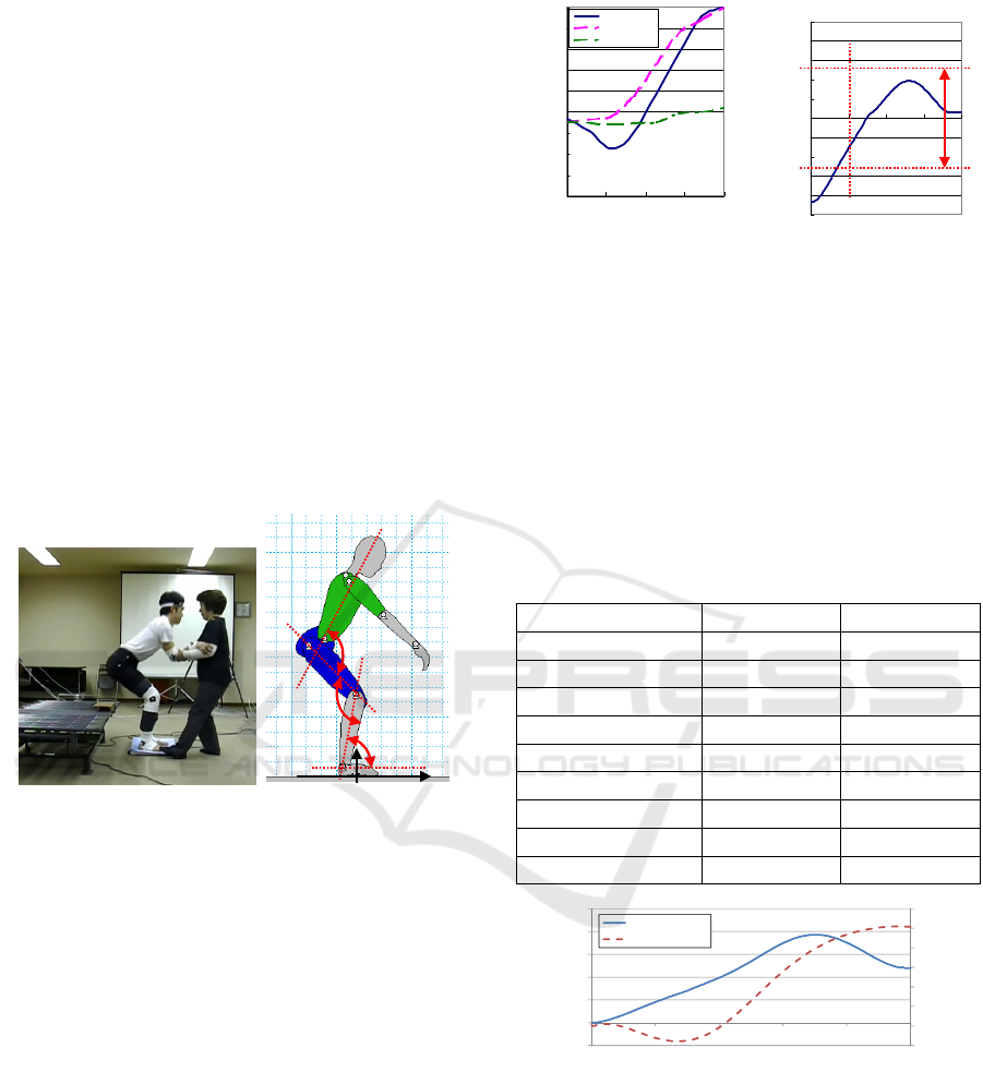
was effective in enabling the patients to stand up
with minimum load (Chugo et al., 2012). We
assumed that the standing motion is symmetrical and
discussed the motion as a movement of the linkages
model on a two-dimensional (2D) plane as shown in
Fig. 6(b) (Nuzik et al., 1986). We measured the
angular values among the linkages as these reflected
the relationship between different parts of a body.
From the measured results, we can verify that to
achieve the motion proposed by Kamiya, a patient’s
trunk needs to incline in the forward direction while
getting up from a chair, as shown in Fig. 7(a). In this
figure, the Y-axis shows the angular values of the
pelvis and trunk, knee, and ankle), whereas the X-
axis shows a movement pattern (Nuzik et al., 1986),
which is the ratio of the standing-up motion, as
shown by (6). Fig. 7(b) shows the position of a
patient’s center of gravity (COG), which indicates
the body balance of the patient during the standing
motion.
θ
1
θ
2
θ
3
X
y
θ
1
θ
2
θ
3
θ
1
θ
2
θ
3
X
y
(a) Assistance motion (b) Its coordination
Figure 6: Standing-up motion as described by Kamiya.
1
θ
shows the angular value of the pelvis and the trunk.
2
θ
and
3
θ
show the angular values of the knee and the ankle,
respectively (Chugo et al., 2012).
To realize this motion, we derived the control
reference of our assistance system kinematically. We
assume the human model as Fig. 6(b) moves each
joint according to the measured values as Fig. 6(a).
For assisting this human model movement, we can
derive the position which the standing manipulator
should assist in standing (Chugo et al., 2012). In this
study, our robot uses them as the control reference.
For this derivation, the parameters were chosen from
the standard data of the body of an adult male
(Okada et. al., 1996), as shown in Table 2.
Fig. 8 shows the positions of the handle in
standing. In Fig. 8, the Y-axis shows the up/down
position (by the standing manipulator) or the
forward/backward position (by a moving function on
a powered walker) of the handle, and the X-axis
0
20
40
60
80
100
120
140
160
180
0255075100
Movement Pattern (%)
Angle (deg)
Pelvis/Trunk
Knee
Ankle
-0.25
-0.2
-0.15
-0.1
-0.05
0
0.05
0.1
0.15
0.2
0.25
0 25 50 75 100
M o ve m e n t P atte rn (% )
Center of gravity
Foot
Lifting up
-0.25
-0.2
-0.15
-0.1
-0.05
0
0.05
0.1
0.15
0.2
0.25
0 25 50 75 100
M o ve m e n t P atte rn (% )
Center of gravity
Foot
Lifting up
(a) Angular values of each joint (b) Its coordination
Figure 7: Analysis of the standing-up motion proposed by
Kamiya. The size of the foot of the human model was
0.26m, and the foot area is shown by the red arrows in (b).
At a 25% movement pattern, the subject lifts up his/her
body.
shows the movement pattern. The coordination of
Fig. 8 is defined as in Fig. 6(b). Using these tracks
as the position control reference, our robot can
realize the standing motion proposed by the nursing
specialist.
Table 2: Human Parameters.
Linkage Name Length [m] Width [m]
Head 0.28 0.21
Trunk 0.48 0.23
Hip 0.23 0.23
Humerus 0.39 0.12
Arm 0.35 0.08
Hand 0.2 0.07
Femur 0.61 0.17
Leg 0.56 0.16
Foot 0.26 0.11
-100
0
100
200
300
400
500
600
-50
0
50
100
150
200
250
0 20406080100
Moving Distance [mm]
(Forward/Backward)
Moving Distance [mm]
(Up/Down)
Movement Pattern [%]
Up/Down
Forward/Backward
Figure 8: The reference in standing.
3.2 Force Guidance in Standing
For guiding the patient to take the inclined posture
when the robot starts to assist in standing, our robot
moves to the forward direction according to the
reference as Fig. 8 and this movement tells the
patient that he/she should incline his/her upper body
to the forward direction. In our previous work, we
found the suitable force applying could tell its user
Development of a Standing Assistance Walker for a Patient with Low Level of Care
147
how the robot would guide him/her (Chugo et al.,
2015). Thus, in section 2.2.3, we propose the wheel
control scheme which has both position control
performance and force control performance.
Proposed controller changes both performance
by two coefficients, B and K in (7). B coordinates
force control performance ratio and K coordinates
position control performance ratio. In this paper, we
investigate the suitable ratio between two parameters
for guiding the patient to the suitable posture by the
preliminary experiment.
3.2.1 Preliminary Experimental Setup
In this experiment, subjects try three test cases as
Table 3. Subjects are 23 young students whose age
are 21 to 24. All subjects use our robot for the first
time and we request them to stand simply according
to the robot’s movement. After this experiment, we
ask them two questions. First question is “Did you
notice the robot tried to make you do what kind of
movement at the beginning?” Second question is
“How feel did you during standing assistance by our
robot?” Seven subjects try the standing assistance
provided by case1, another eight subjects are case2
and another eight subjects are case3.
Table 3: Test cases in the preliminary experiment.
B K
Case 1: Force mode 0.8 0.2
Case 2: Moderate Mode 0.5 0.5
Case 3: Position Mode 0.2 0.8
3.2.2 Preliminary Experimental Results
Table 4 shows the experimental results. By standing
assistance by our robot, in case2, almost all subjects
can stand according to the reference. On the other
hand, in case1, in some trials, the subject fails to
stand. Fig. 9(a) shows the typical failure. In this
failure, the subject noticed the robot tried to guide to
the forward direction by its force. However, the
subject could not find the suitable position because
the robot did not show the reference position clearly
because of the low position control ratio, and as the
result, the subject failed to stand as Fig.9 (a). In
case3, the subject also failed to stand in some trials
as Fig. 9(b). In this failure, the subject did not notice
the robot guided to the forward direction because the
guidance force was weak. As the result, the subject
did not move the position of COG to the forward
direction and his body balance was unsuitable.
From the questionnaire results as Table 4, in
case1 and 2, almost all subjects noticed the robot
guidance to the forward direction, thus, force control
approach seems to be effective for this purpose.
However, too strong force causes the subject felt a
fear and should be avoided by the results in Table 4.
In case3, some subjects did not notice the robot
guidance to the forward direction and it causes the
standing assistance was uncomfortable. This means
to provide the effective standing assistance, the
powered walker should have both position control
function and force control function.
From these results, our powered walker uses the
parameter settings as case2 which activates both
position and force control function in standing.
Table 4: Experimental Results and Questionnaire
Answers.
Case1 Case2 Case3
Success in standing by
our robot
5/7
71%
7/8
88%
4/8
50%
Question 1: The inclined
body posture
7/7
100%
7/8
88%
5/8
63%
Question 2: Fear or
uncomfortable
3/7
43%
0/8
0%
3/8
38%
Too Forward
Not Enough to
Forward
(a) case1 (b) case3
Figure 9: Typical failure of standing.
3.3 Assistance Procedure with Voice
Instruction
For safety standing, our robot guides the patient by
voice instruction. At the beginning in standing, the
patient’s upper body needs to incline in the forward
direction. From the opinions of the physical
therapists, these information are required for the
patient to take this posture.
The patient should incline his/her upper body to
the forward direction.
The patient should face to the bottom of the
forward direction.
ICINCO 2017 - 14th International Conference on Informatics in Control, Automation and Robotics
148
The foot should move to the back position,
should not take the posture which throws out
his/her leg.
Considering with them, we propose the
assistance sequence with voice instruction as Fig. 10.
Table 5 shows the voice instructions provided in
Japanese by the device as well as their English
translations.
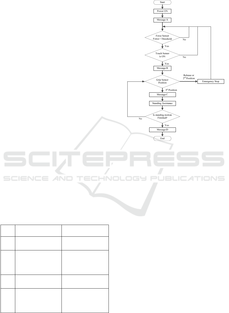
When a user turns on the power of the walker, an
announcement (Message A) is spoken. After that,
the walker remains in a waiting state until both touch
sensors and force sensors are turned on. The user has
to touch the gripping switches and put their weight
onto the armrests, because the device must first
check whether the user is holding the walker
properly to decide whether it is safe to provide the
assistance.
If these sensors respond, a voice announcement
(Message B) tells the user to stand ready to move.
After this, when the user grips the switches on the
handle as the first-step input shown in Fig. 5, the
device initiates its standing assistance. The user has
to continue holding the switches on the first-step
input, as elderly people generally tend to release
their grasp or become stiff if they feel scared (Omori
et al., 2001). Thus, if the user releases its grip, the
second-step input or no input, the system stops the
assistance. When no further assistance is required,
the actuators stop moving and a voice announcement
encourages the user to walk.
During the standing motion, our device leads
user to a suitable standing posture using the two
DOF (i.e., the up/down direction and
forward/backward direction).
After the user stands up, they can use the device
as a powered walker (Hirata et al., 2007).
Table 5: Voice Announcements.
No Voice Message Its Objective
A I’ll do my best to
support you.
Saying hello to the
user.
B Move your feet back
and bend your body to
forward. Then, grip the
switches on the handle.
Telling the user to
ready his/her posture to
stand up soon.
C Let’s stand up together. Signal of start of the
standing up motion.
D Have done. Let’s walk
carefully with me.
Signal of end of the
standing up motion and
encouraging the user to
walk.
Figure 10: Standing assistance process flow.
4 ASSISTANCE PROCEDURES
To confirm the efficiency of the proposed assistive
robot, we conducted a practical experiment.
4.1 Experimental Setup
To verify its effectiveness, we used three test cases.
In case1, our proposed system assisted a standing
motion with all proposed technique. In case2, our
system assisted a standing motion without proposed
force guidance function (only velocity control,
B=K=0 in (7)), because it simulates standing
assistive devices traditionally provided by many
manufacturers (Funakubo et al., 2001). In case3, our
system assisted a standing motion with only the
standing manipulator, and it simulates the automatic
movable handrail equipped the bedside which is
widely used in care houses and hospitals.
We used four subjects. All subjects were elderly
or handicapped people with disabilities and required
standing assistance in their daily activities. All the
details about these four subjects are provided in
Table 6.
Development of a Standing Assistance Walker for a Patient with Low Level of Care
149
During this experiment, we measured the body
movement by the motion capture system and the
applied force to the up/down and the forward/
backward direction by equipped sensors on our robot.
Using measured values, we can estimate the traction
output of waist, knee and ankle joint as an index of
the physical load of the patient. For detail estimation
scheme, please refer our previous research (Chugo et
al., 2015).
All the experiments were performed by nursing
specialists and under the ethical rules and technical
safety measures provided by the Yokohama
Rehabilitation Center, Shin-Yokohama, Kanagawa,
Japan.
Table 6: Subjects.
No
Weight
/Height
Age
Care
Level
Remarks
A
60kg
/170cm
60 Level2
Peripheral
neuropathy,
Paraplegia
B
78kg
/178cm
52 Level2
Ataxic both sides
hemiplegia
C
68kg
/152cm
68 Level2
Limb paralysis,
Parkinson's disease
D
58kg
/178cm
34 Level1
Hypoxic
encephalopathy,
Limbs and trunk
ataxia
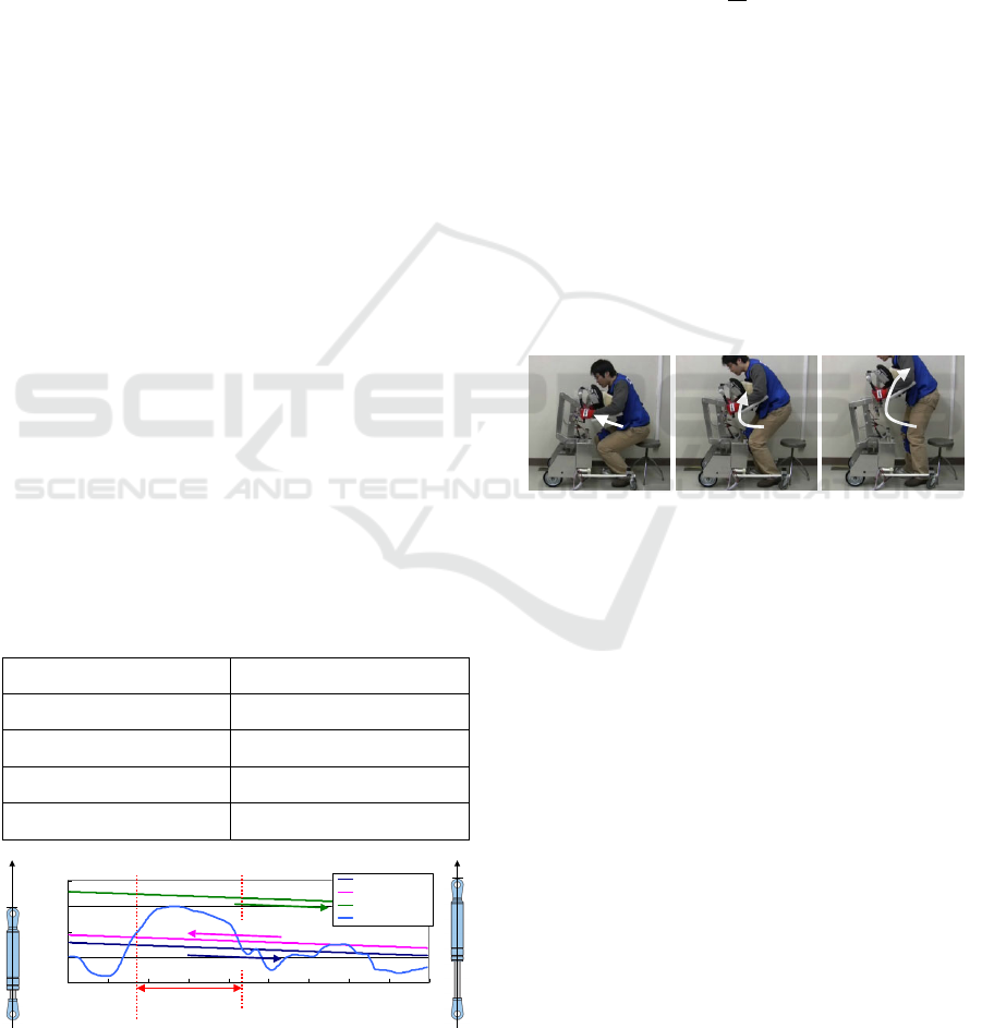
4.2 Experimental Results
Figs. 11–14 are visual descriptions of the
experiments. Fig. 11 describes a series of standing
scenes of subject A, whereas Fig. 12 is about subject
B, Fig. 13 is about subject C, and Fig. 14 is about
subject D. These pictures show that all the subjects
were able to stand up without the occurrence of any
accidents.
(a) 20% (b) 50% (c) 100%
Figure 11: Subject A (Case1).
(a) 20% (b) 50% (c) 100%
Figure 12: Subject B (Case1).
(a) 20% (b) 50% (c) 100%
Figure 13: Subject C (Case1).
(a) 20% (b) 50% (c) 100%
Figure 14: Subject D (Case1). For safety reason, a
therapist stays near the subject during this experiment.
All subjects evaluated our assistance robot using a
questionnaire after the experiment as Table 7. The
subjects A to C evaluated case1 is better and on the
basis of their responses, we were able to tell that
leading to the suitable posture was important during
the standing assistance. Subject D, meanwhile,
found case 3 to be better because he had limbs and
trunk ataxia caused by hypoxic encephalopathy and
leaned completely against our assistance system.
Fig. 15 shows the estimated torque on the ankle,
knee, and waist of subject A on each case.
Furthermore, we show the estimated torque when he
stands up only by his own physical strength using a
handrail equipped on the bedside. In Fig.15(a)
without assistance case, maximum traction is about
1.0 Nm/kg on a knee joint. In Fig.15(b), traction is
within 0.5Nm/kg in case1, in Fig.15(c), traction is
within 0.8 Nm/kg in case2 and in Fig.15(d), traction
is within 0.6 Nm/kg in case3. From previous
ICINCO 2017 - 14th International Conference on Informatics in Control, Automation and Robotics
150
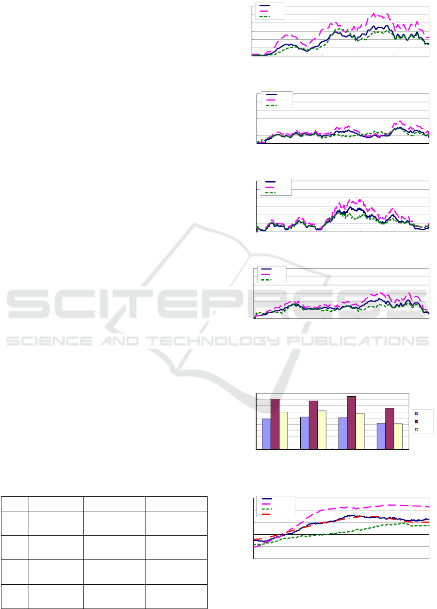
research, maximum traction should be within 0.5
Nm/kg for safety standing motion by own physical
strength of elderly people (Fisher et al., 1990).
Case1 has a best assistance performance and this
result indicates the suitable posture during standing
motion is maintained using our ideas. Furthermore,
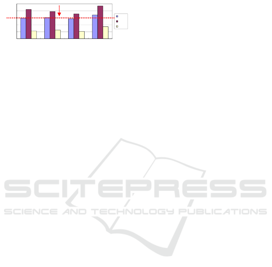
Fig. 16 shows maximum traction output of a knee
joint when the subjects A to D lift up his body.
According to these results, the subjects were
supported with the lowest burden in all of the three
cases, and case1 has best assistance performance in
standing.
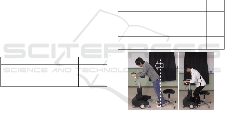
Fig. 17 shows the position of the COG on the
forward/backward direction of subject A. These
results were calculated according to the linkage
model and the assumptions outlined in section 3.1.
As shown in Fig. 17, the COG movement in case 1
was closest to the reference. In case 2, the COG was
over 20 cm, which means that the traditional
controller led to the users learning too far forward.
In contrast, in case 3, the COG was less than 10 cm,
which implies that the users did not move forward
enough to bend their body or may be led in danger.
Moreover, Fig.18 shows the COG of subject A to D
at 60 % movement pattern. At this time, subjects
incline their trunk and lift up it to upper position.
According to this result, in all subjects, the COG fit
the designed reference and we can evaluate the body
balance is suitable in case1. In case2, the COG is too
far and in case 3, the COG is too close. These
unsuitable COG lead a risk of falling down and in
the questionnaire results as Table 6, some subjects
feels it. On subject D, COG tends to be large value
because this subject leaned completely against our
assistance system.
According to these results, our robot succeeds to
assist the subjects with the lowest burden and
suitable body balance during standing motion with
proposed robot system (case1). Moreover case3
(position fix version) may be effective when the
target user completely does not have dexterity to
maintain a body balance.
Table 7: Questionnaire results.
No Case1 Case2 Case3
A Good
Body balance is
bad.
Body balance is
bad.
B Good Fear of falling.
Body balance is
bad.
C Good
Acceptable, case
1 is better.
Body balance is
bad.
D
Acceptable,
case3 is better.
Fear of falling. Good
0
0.2
0.4
0.6
0.8
1
1.2
0 20406080100
Torque [Nm/kg]
Movement Pattern [%]
Ankle
Knee
Waist
(a) Without Assistance
0
0.2
0.4
0.6
0.8
1
1.2
0 20406080100
Torque [Nm/kg]
Movement Pattern [%]
Ankle
Knee
Waist
(b) Case1
0
0.2
0.4
0.6
0.8
1
1.2
0 20406080100
Torque [Nm/kg]
Movement Pattern [%]
Ankle
Knee
Waist
(c) Case2
0
0.2
0.4
0.6
0.8
1
1.2
0 20406080100
Torque [Nm/kg]
Movement Pattern [%]
Ankle
Knee
Waist
(d) Case3
Figure 15: Traction output of each joint (Subject A) during
standing motion.
0
0.1
0.2
0.3
0.4
0.5
0.6
0.7
0.8
0.9
Subject A Subject B Subject C Subject D
Traction [Nm/kg]
Case1
Case2
Case3
Figure 16: The maximum traction output in each subject.
-200
-100
0
100
200
300
0 20406080100
Position of COG [mm]
Movement Pattern [%]
Case1
Case2
Case3
Reference
Figure 17: The position of COG (Subject A) during
standing motion.
Development of a Standing Assistance Walker for a Patient with Low Level of Care
151
0
50
100
150
200
250
Subject A Subject B Subject C Subject D
Position of COG [mm]
Case1
Case2
Case3
Figure 18: The position of COG at 60[%] movement
pattern in each subject.
5 CONCLUSIONS
This paper proposes a novel low cost robotic walker
with standing assistance. Proposed robot focuses on
domestic use for elderly people who is low level of
care and need nursing in their day-to-day lives. For
the robot to be used widely and easily in daily life,
it is important to ensure safety and provide an
inexpensive manufacturing cost.
For realizing two opposed requirements, this
paper proposes the novel mechanism design and the
assistance procedure which leads the patient safety
and stability. Proposed mechanical design uses a gas
spring which helps the lifting linear actuator with
minimum cost and developed robot assists the
patient with wheel actuators on a powered walker
for stabilizing its user as well as for lifting up the
user. Furthermore, proposed assistance procedure
leads the patient to suitable posture by the force
guidance and voice instruction. For realizing it, we
investigate what factor is useful for leading the
patient by preliminary experiment.
The developed prototype has enough assistance
performance through experiments with elderly and
handicapped subjects. Thus, our study succeeds to
develop a safety and low cost robot which has
enough standing assistance performance for the
patient who is low level of care.
For our future work, we plan to develop the
wheel control algorithm for walking assistance.
ACKNOWLEDGEMENTS
The authors would like to thank T. Kumeda, a
physical therapist, and all the staff members at
Yokohama Rehabilitation Center for providing
technical assistance in the experiments.
This work is supported in part by the Matching
Planner Program (MP28116808328) from Japan
Science and Technology Agency (JST), Grant-in-
Aid for Scientific Research C (16K01580) from
Japan Society for the Promotion of Science (JSPS)
and the Robotic Devices for Nursing Care Project
from Japan Agency for Medical Research and
Development, AMED.
REFERENCES
N. B. Alexander, A. B. Schultz and D. N. Warwick, 1991.
Rising From a Chair: Effects of Age and Functional
Ability on Performance Biomechanics. In J. of
Geometry: MEDICAL SCIENCES, Vol.46, No.3,
M91-98.
M. A. Hughes, M. L. Schenkman, 1996. Chair rise
strategy in the functionally impaired elderly. In J. of
Rehabilitation Research and Development, Vol.33,
No.4, pp.409-412.
Cabinet Office, Government of Japan, 2016. KOUREISHA
HAKUSHO (The whitepaper on the aged society),
ISBN: 4865790519, pp.25, (in Japanese).
K. Nagai, I. Nakanishi and H. Hanabusa, 2003. Assistance
of self-transfer of patients using a power-assisting
device. In Proc. of the IEEE Int. Conf. on Robotics
and Automation, pp.4008-4015.
A. Funakubo, H. Tanishiro and Y. Fukui, 2001. Power
Assist System for Transfer Aid. In J. of the Society of
Instrument and Control Engineers, Vol.40, No.5,
pp.391-395.
M. Hirvensalo, T. Rantanen and E. Heikkinen, 2000.
Mobility difficulties and physical activity as predictors
of morality and loss of independence in the
community-living older population. In J. of the
American Geriatric Society, Vol.48, pp.493-498.
B. J. Munro, J. R. Steele, G. M. Bashford and M, Ryan,
1998. A kinematic and kinetic analysis of the sit-to
stand transfer using an ejector chair: implications for
elderly rheumatoid arthritic patients. In J. of
Biomechanics, pp.263-271.
D. Chugo, Y. Morita, Y. Sakaida, S. Yokota, H.
Kobayashi, H. Hashimoto and K. Takase, 2012.
Standing Assistance Control using a Physical Strength
of a Patient with Load Estimation. In Proc. of 21st
IEEE Int. Symp. on Robot and Human Interactive
Communication, pp.234-239.
D. Chugo, T. Yamada, S. Muramatsu, S. Yokota, and H.
Hashimoto, 2015. Assistive Robot for Standing with
Physical Activity Estimation based on Muscle
Arrangements of Human Legs. In Proc. of 12th Int.
Conf. on Informatics in Control, Automation and
Robotics, pp.35-43.
E. Maki, P. J. Holliday and A. K. Topper, 1991. Fear of
falling and postural performance in the elderly. In J. of
Gerontology, Vol.46, No.4, pp. 123-131.
K. Kamiya, 2005. Development and evaluation of life
support technology in nursing. In Proc. of 7th RACE
Symp., Research into Intelligent Artifacts for the
Generalization of Engineering, pp.116-121.
D. Chugo, E. Okada, K. Kawabata, H. Kaetsu, H. Asama,
N. Miyake, and K. Kosuge, 2006. Force Assistance
r
eference
ICINCO 2017 - 14th International Conference on Informatics in Control, Automation and Robotics
152

Control for Standing-Up Motion. In Proc. of the First
IEEE/RAS-EMBS Int. Conf. on Biomedical Robotics
and Biomechatronics, DOI: 10.1109/BIOROB.2006.
1639073.
S. Nuzik, R. Lamb, A. Vansant and S. Hirt, 1986. Sit-to-
Stand Movement Pattern, A kinematic Study. In
Physical Therapy, Vol.66, No.11, pp.1708-1713.
H. Okada, M. Ae, N. Fujii and Y. Morioka, 1996. Body
Segment Inertia Properties of Japanese Elderly. In
Biomechanisms, No.13, pp.125-139.
D. Chugo, S. Aburatani, T. Masushige, S. Muramatsu, S.
Yokota and H. Hashimoto, 2015. A Hand Movement
which shows the Intention of a Robotic Guide for Safe
Walking, In Proc. of the 24th Int. Symp. on Industrial
Electronics, pp.940-945.
Y. Hirata, A. Hara, and K. Kosuge, 2007. Motion Control
of Passive Intelligent Walker Using Servo Brakes. In
IEEE Trans. on Robotics, pp.981-990.
K. Omori, Y. Yamazaki, H. Yokoyama, U. Aoki, M.
Kasahara, K. Hiraki, 2001. The relationship between
strength in the lower extremity and the ability to stand
up from a chair in elderly inpatients. In Sogo
Rehabilitation. Vol.30, No.2, pp.167-171.
N. M. Fisher, D. R. Pendergast and E. C. Calkins, 1990.
Maximal Isometric Torque of Knee Extension as a
Function of Muscle Length in Subjects of Advancing
Age. In Arch. Phys. Med. Rehabil., Vol.71, No.10,
pp.729-734.
Development of a Standing Assistance Walker for a Patient with Low Level of Care
153
