
Two Mobile Robots Platforms for Experimentation: Comparison and
Synthesis
Ernesto Fabregas
1
, Gonzalo Farias
2
, Emmanuel Peralta
2
, Jos
´
e S
´
anchez
1
and Sebasti
´
an Dormido
1
1
Departamento de Inform
´
atica y Autom
´
atica, Universidad Nacional de Educaci
´
on a Distancia, Madrid, Spain
2
Pontificia Universidad Cat
´
olica de Valpara
´
ıso, Av. Brasil 2147, Valpara
´
ıso, Chile
Keywords:
Wheeled Mobile Robots, Experimental Environments.
Abstract:
This paper presents a comparison between two ready-to-use platforms developed for both teaching and re-
search purposes with wheeled mobile robots. The platforms are divided into two parts: a simulation and a real
experimental environment. In both cases, the experimental environments uses a camera and a PC (with the
corresponding software tools) as positioning sensor to locate the robots in the work-space. The comparison
includes software, hardware and usability points of view.
1 INTRODUCTION
Distributed systems are based on the idea of dividing
complex problems into coordinate actions of multiple
agents on a network that cooperate together to per-
form relatively simple tasks. In this sense, a group
of robots that can communicate between them is a
perfect scenario to test this kind of collaborative ap-
proaches.
Mobile robots are autonomous systems that can
perform different tasks. A complex task (e.g. to keep
a formation around a robot) can be divided in singles
tasks in order to perform an individual position con-
trol algorithm on each robot (Guinaldo et al., 2013).
The implementation of this kind of experiments
can be difficult. First of all, we need to have a plat-
form to test these developments with real robots in a
lab. On the other hand, the complexity of the exper-
iments that can be carried out depends on the robot’s
sensors, specifically, their quality and precision. For
instance, if you want to develop obstacles avoidance,
line following, or a position control experiment, the
robot needs to know its position in running-time. This
is a problem to face in indoors environments because
the GPS does not work in this kind of situations. Be-
sides if you want to develop distributed experiments
where the robots cooperate with a common goal, then
the robots need communication to share information
(Casini and Garulli, 2016).
This paper compares two platforms developed
to implement this hands-on experiments with two
wheeled mobile robots: Moway robots (Innova, 2012)
and Khepera IV robots (KTeam, 2015). In both cases
the virtual and real experimental environments were
designed and developed considering these robots.
Both platforms have been designed for educational
purposes, but they can be used for researching pur-
poses as well.
In the first case the simulation was developed
with Easy Java Simulations (EJS) (Esquembre, 2012).
Which is a free software tool for creation of simu-
lations in Java with a high level of graphic capabil-
ities and an increasing degree of interactivity with
JavaScript support. In the second case the simulator
used was V-REP, which is the most used simulator in
robotics nowadays (Rohmer et al., 2013).
The experimental environment has been designed
and implemented based on previous experiences of
the authors developing remote laboratories (Neamtu
et al., 2011; Chaos et al., 2013). In both cases we have
implemented an Indoor Positioning System (IPS) us-
ing the images of camera installed on the ceiling of
the lab and Swistrack (Lochmatter et al., 2008). This
software is an open source tool developed at the EPFL
for the tracking of robots, animals and objects using a
camera.
The remainder of the paper is organized as fol-
lows: Section 2 presents and describes briefly the the-
oretical aspect related to the control of wheeled mo-
bile robots. Section 3 describes the platform of the
Moway robots. Section 4 describes the platform for
the Khepera IV robots. Section 5 makes a compari-
son between these two platforms. Finally, Section 6
presents the main conclusion and future work.
Fabregas, E., Farias, G., Peralta, E., Sanchéz, J. and Dormido, S.
Two Mobile Robots Platforms for Experimentation: Comparison and Synthesis.
DOI: 10.5220/0006469004390446
In Proceedings of the 14th International Conference on Informatics in Control, Automation and Robotics (ICINCO 2017) - Volume 2, pages 439-446
ISBN: Not Available
Copyright © 2017 by SCITEPRESS – Science and Technology Publications, Lda. All rights reserved
439
2 CONTROL EXPERIMENTS
Both robots used in the platforms are based on the dif-
ferential model. In this model the movement is based
on two separately driven wheels placed on either side
of the robot body. It can thus change its direction by
varying the relative rate of rotation of its wheels. The
linear and angular velocities (ν, ω) are obtained from
the differential model of a wheeled robot. While the
kinematic model of the robot (Eq. 1) can be obtained
in cartesian coordinates (Chwa et al., 2006), where θ
is the heading direction angle of the robot and (x
c
,y
c
)
is the current position of the robot.
˙x
c
= ν cosθ
˙y
c
= ν sin θ
˙
θ = ω
(1)
In this section two control problems with mobile
robots, based on the feedback control loop scheme
are described: 1) Position control, and 2) Leader-
followers formation control.
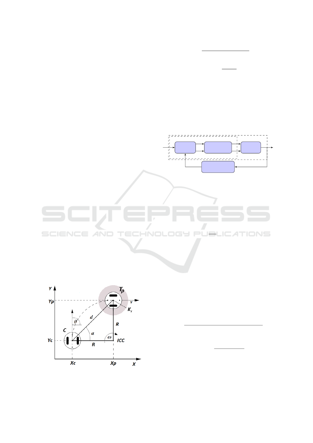
2.1 Position Control
This problem is titled position control or point sta-
bilization of a differential wheeled mobile robot. Its
objective is to drive the robot from the current posi-
tion C(x
c
, y
c
) and orientation (θ) to the target point
T
p
(x
p
, y
p
), as it is shown in Figure 1. R is the distance
from the center between the wheels to the ICC (In-
stantaneous Center of Curvature). This problem has
been widely studied mainly due to the designing of
the control law, under nonholonomic constraints, in-
troduces challenging control problems from the aca-
demic and research points of view (K
¨
uhne et al.,
2005). In order to achieve the control objective, the
distance (d) and the angle (α) between the points C
and T
p
are calculated with Eq. 2 and 3.
Figure 1: Position control problem.
d =
q
(y
p
− y
c
)
2
+ (x
p
− x
c
)
2
(2)
α = tan
−1
y
p
− y
c
x
p
− x
c
(3)
Figure 2 shows the control blocks diagram of this
problem. The robot tries to minimize the orientation
error, θ
e
= α − θ, and at the same time, to reduce the
distance to the target point (d = 0). Eq. 2 and 3 are
implemented in the block Compute; by using as ref-
erence the target point (T
p
) and the current position
of the robot (C). These two values and the orienta-
tion θ are used by the Control Law block to obtain the
control signals (velocities).
Compute
Control Law
Wheels
Robot
Controller
Position Sensor
T
p
d
α
ν
ω
x, y, θ
C
Figure 2: Diagram of the position control problem.
Equations 4 and 5 represent the implementation
of the Control Law block. Where ν
max
is the maxi-
mum linear velocity, K
r
is the radius of a docking area
(around the target point) and ω
max
is the maximum
angular velocity of the robot (Villela et al., 2004).
ν =
(
ν
max
i f
|
d
|
> K
r
d
ν
max
K
r
i f
|
d
|
≤ K
r
(4)
ω = ω
max
sin(θ
e
) (5)
2.2 Leader-Followers Formation
In this experiment one robot is defined as leader and
the rest of them as followers. All robots implement
the position control experiment. But in the case of the
followers robots, they use the position of the leader as
target point to reach the formation around it. The fol-
lowers implement Equations 6 and 7 where the point
(x
d
n
, y
d
n
) represents the distance from the master to
the corresponding slave in the formation.
d
n
=
q
(y
p
n
− y
c
n
− y
d
n
)
2
+ (x
p
n
− x
c
n
− x
d
n
)
2
(6)
α = tan
−1
y
p
n
− y
c
n
− y
d
n
x
p
n
− x
c
n
− x
d
n
(7)
During the experiment the formation can be lose
because the leader does not take into account the
formation (non-cooperative approach). If the leader
robot take into account the position of the followers
ICINCO 2017 - 14th International Conference on Informatics in Control, Automation and Robotics
440
into the formation then the formation is maintained
during the displacement (cooperative approach). To
do it the leader robot calculates its linear velocity us-
ing its position error and the error of the formation as
is shown in Eq. 8 (Lawton et al., 2003).
E
f
(t) =
N
∑
n=1
E
pi
(t) (8)
Where E
f
is the total error between the current po-
sition of the followers (N) and the desired formation
pattern (E
pi
). The velocity of the leader depends on
its own position error (E
pl
) proportionally (through a
gain K
p
) and the formation error (E
f
) through a gain
K
f
, which decide the influence of the formation error
in the speed of the leader.
ν
l
(t) = K
p
E
pl
(t)− K
f
E
f
(t) (9)
3 Moway PLATFORM
This platform has been titled RFCP (Robots Forma-
tion Control Platform). It consists of two main parts:
the RFCSIM (Fabregas et al., 2014) which is a simu-
lator for virtual experiments with Moway robots and
the RFCEXP (Fabregas et al., 2015) which is an ex-
perimental environment for laboratory practices.
3.1 RFCSIM
The RFCSIM is a simulator in 2D that has been de-
veloped using EJS. Simulations are structured by EJS
into three categories: Description, Model and View.
The Model is divided into sections (Variables, Initial-
ization, Evolution, Fixed relations, Custom and Ele-
ments). All of these sections can contain Java code
used in different parts of the simulation in run-time.
The Variables section contains all the variables used
in the simulation. The Initialization contains some
lines of code necessary to initialize parameters of the
simulation; Evolution is the most important section
because it includes the code that will be executed at
each step of the simulation, such as the ordinary dif-
ferential equations of the model. The Fixed relations
panel allows defining the constraints of the model, the
control algorithm or the view.
In the Evolution some parameters of the simula-
tion can be established: number of frames per second,
time increment and the method to solve the ordinary
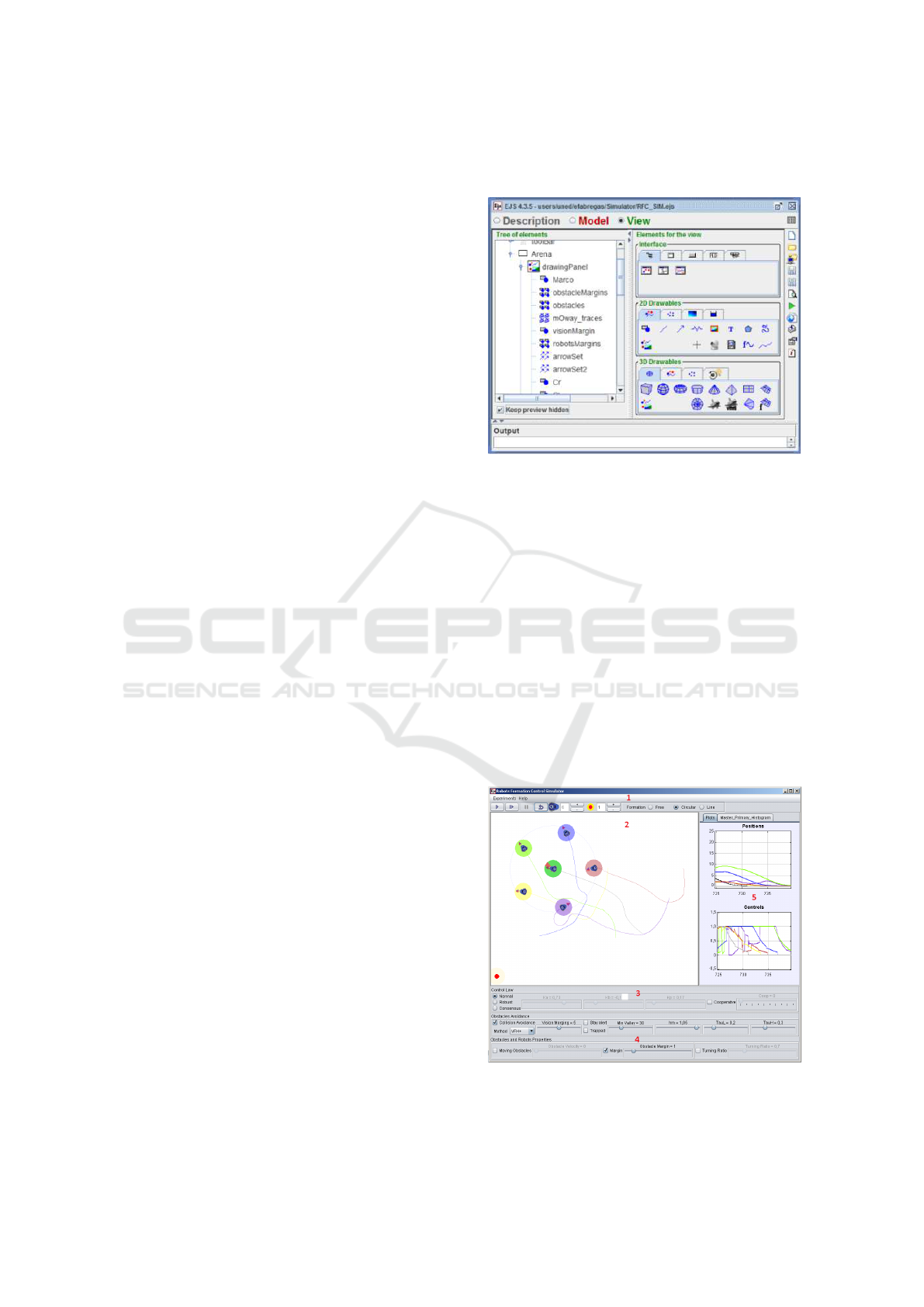
differential equations. On the other hand, the View
(Fig. 3) allows creating the GUI that includes visual-
ization, user interaction, and simulation control. The
View elements can be chosen from a set of predefined
components to build a tree-like structure. All of these
visual components are interconnected between them,
with the variables and the Java code of the Model.
Figure 3: EJS View of RFCSIM.
The main window of RFCSIM is divided into five
main panels (see Fig. 4). With panel No.1 users can
save and load experiments, get some help, manage the
execution of the simulation (play, pause and step), se-
lect the formation (free, circular, line) and establish
the number of robots and obstacles for the experi-
ments. Panel No. 2 shows the scenario of the ex-
periments with the obstacles, the robots and a trace
of the trajectory followed by each robot. Users can
change the robots and obstacles positions by dragging
and dropping them during an experiment. The effect
of these actions is different if the formation mode is
free or other option is selected. In the first case, the
user can set a new formation by dragging and drop-
ping the robots. In other cases this acts over the robots
as a disturbance.
Figure 4: RFCSIM main window.
Two Mobile Robots Platforms for Experimentation: Comparison and Synthesis
441
Panel No. 3 is to define the properties of the se-
lected obstacle avoidance algorithm (VFF, VFH
∗
or
VFH
+
). Panel No.4 is to define physical properties of
the robots (minimum turning radius and control law)
and obstacles (size, velocity and security margin size
around them). Panel No. 5 is a tabbed panel with two
tabs. In the first tab two graphics are shown: the po-
sition of the robots and the control law signals and a
polar histogram of the master robot.
3.2 RFCEXP
RFCEXP has been developed to carry out posi-
tion control experiments with Moway robots (Innova,
2012) taking into account their properties and fea-
tures. Moway is an small wheeled mobile robot based
on a differential model.
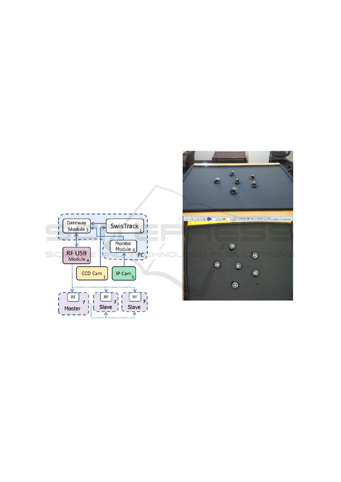
To implement this kind of experiments, the robots
need to know their absolute positions and to com-
municate between them. The setup is composed of
five hardware and three software components that are
deeply related. Fig. 5 shows the architecture and the
relations between these elements.
Figure 5: Architecture of the experimental environment.
A Personal Computer (PC) runs the software com-
ponents and has a CCD camera connected via a
FireWire port. The camera is installed on the ceiling
of the laboratory and is in charge of obtaining live im-
ages of the experiments. These images are processed
by SwisTrack. This application computes the absolute
positions of each robot and builds a data packet with
this information. This packet is sent via TCP/IP port
to the Gateway Module.
The Gateway Module is an application developed
using Visual C#. This program performs three main
tasks: 1) It processes the packet received from Swis-
Track; 2) It sends the information to the correspond-
ing robot using the RF USB Module, and 3) It receives
and responds the request from the Monitor Module.
The RF USB Module is a hardware component
of the Moway robot for the communication between
them and the PC using RF (Radio-Frequency).
The Monitor Module is a software application de-
veloped using EJS. Its main purpose is the interaction
between users and robots by visualizing the behavior
of the experiment using the video streaming of an IP
camera. The users can also send information to the
robots. For example, they can set the initial position
of the robots at the beginning of an experiment, or
send the reference to a robot during an experiment.
Figure 6: Experiment of robots formation control.
The most important components of this setup are
the Moway robots (No. 7). They are autonomous
small programmable robots designed mainly to per-
form practical applications, teaching robotics, tech-
nology, electronics, and control. They represent a
complete low-cost learning solution that allows users
to program an electronic control through simple and
intuitive software. The main components of these
robots are: two independent servo motors, a light
sensor, a temperature sensor, two infrared line sen-
sors, four LED diodes, a three-axis accelerometer
and a wireless module for communication by radio-
frequency. All these peripherals are connected to the
micro-controller that governs the robot.
Fig. 6 shows an experience with the experimental
ICINCO 2017 - 14th International Conference on Informatics in Control, Automation and Robotics
442
environment (top image is from a video streaming and
bottom image is form the Monitor Module). In this
case the with 1 robots as master and 5 robots as slaves
making a circular formation around him. The slaves
have to maintain the constant the their positions in re-
spect to the master’s position. Note that in this kind
of experiments, robots need to communicate between
them because the slaves need to know the position of
the master (as reference) to make the formation.
4 Khepera IV PLATFORM
This platform has been titled KH4P (Khepera IV Plat-
form). It consists of two main parts: the KH4VREP
(Peralta et al., 2016) which is a model of the Khepera
IV robot for V-REP simulator and KH4EXP which is
an experimental environment for laboratory practices
with the Khepera IV robot.
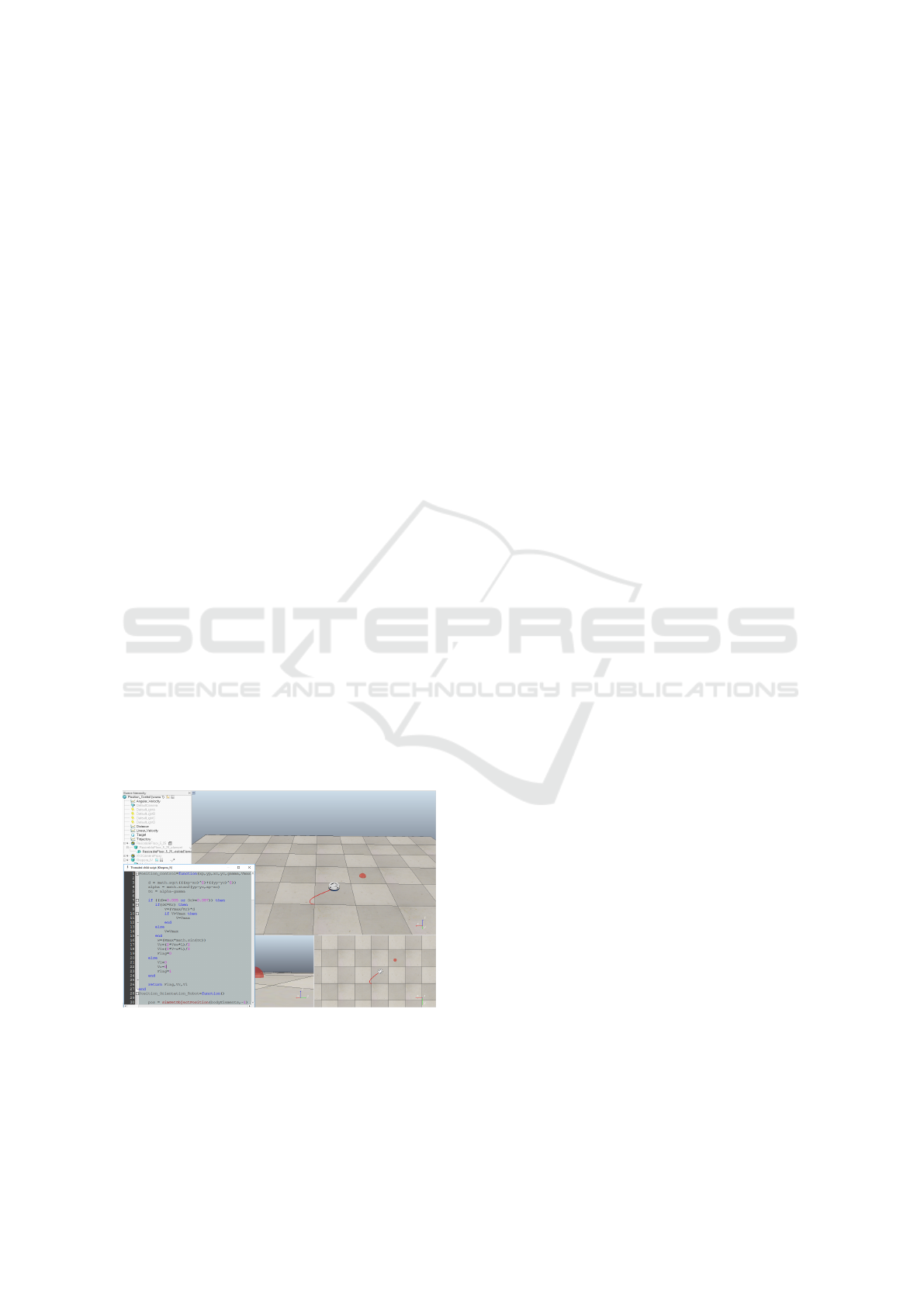
4.1 KH4VREP Library
In this case each visual component of the Khepera IV
robot (case, base, wheels, among others) was care-
fully modeled in 3D using Autodesk Inventor. The
obtained prototype was imported into V-REP as .stl
format. As final step, the model was assembled in V-
REP. Most sensors of the robot were designed based
on the V-REP Khepera III model. In the case of the
camera (which is not included in previous Khepera
family version) was configured based on the existing
camera of V-REP library. The integration of the model
into V-REP allows the interaction with a large number
of examples, models of robots, sensors and actuators
that comes with it.
Figure 7: Khepera IV Library example.
To create an experiment is as simple as dragging
and dropping the robot model into the workspace and
program the script associated to the robot. When the
model is added to the virtual world of V-REP, it can
interact with the included models during the running
time. Also other new models can be designed and
added to V-REP to implement customized simulation
experiments. Figure 7 shows the library running an
example of a position control experiment.
4.2 KH4EXP
As in the previous approach, the main purpose of this
new platform is also to perform control experiments
with real mobile robots. In this case, the mobile robot
is a Khepera IV (KTeam, 2015). This is the fourth
generation of the Khepera robots family of the Swiss
company K-TEAM.
Khepera IV is a wheeled mobile robot that has
been designed for indoor pedagogical purposes and
it brings numerous features, for example, a colour
camera, Wi-Fi and Bluetooth communications, an ac-
celerometer, a gyroscope, improved odometry and
precision, an array of 8 infrared sensors for obstacle
detection, 5 ultrasonic sensors for long range object
detection, 2 very high quality DC motors and a Linux
operating system core.
In this implementation, the robot is connected to
a Wi-Fi router that allows wireless communication of
the robot with other components of the platform: the
IPS and the Monitor Module. Almost any existing
C/C++ library can be easily ported on the Khepera
IV, allowing the development of portable embedded
algorithms and applications.
As is known the GPS does not work on indoors
environments. That is why it is necessary the imple-
mentation of a positioning system to develop position
control experiments. As in the previous approach, a
PC has been used as the “brain” of the system, but in
this case with Linux. The PC is in charge of ruining
the software components of the system (SwisTrack)
and the Monitor Module.
A PlayStation 3 (PS3) USB camera (fixed to the
ceiling) is connected via USB to the PC. The images
of this camera are processed to obtain the position of
the robot. Figure 8 shows the architecture of the plat-
form with all software and hardware components and
their interactions. Note that the red line encloses the
components of the positioning system and the green
line encloses the components of the Monitor Module.
Monitor Module has been developed in Easy Java
Simulations (EJS) and it allows the interaction be-
tween users and the robot. Its GUI shows the stream-
ing of the IP camera. By clicking on the image the
target point for the position control of the robot can
be set. Monitor Module is also in charge of two
other tasks: a) the communication with SwisTrack via
TCP/IP client at port 30001 (labelled as 2 in Fig. 8);
Two Mobile Robots Platforms for Experimentation: Comparison and Synthesis
443
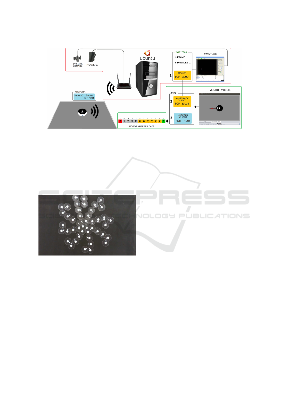
Figure 8: Platform architecture.
and b) the communication with the robot using a wire-
less router via TCP/IP client through port 1291 (la-
belled as 3 in Fig. 8).
Figure 9 shows shows a sequence of images of the
control position experiment for eight different initial
positions and orientations. In all cases the target point
is T
p
(0;0). As can be seen, due to the initial orienta-
tion and position of the robot, each experiment de-
scribes a different trajectory.
Figure 9: Image sequence of the Position Control experi-
ments.
4.3 Advanced Proposed Experiments
The platform is a ready to use tool that allows the im-
plementation of different experiments to study some
interesting problems of mobile robots. These experi-
ments can include sensing and movement tasks for a
single robot or cooperation in a multi-robot scenario.
Some of the experiments that could be implemented
with the developed platform are the following:
• Obstacle avoidance: Using the proximity sensors
and their location on the robot, other algorithms
of obstacle detection and avoidance can be imple-
mented (Yang et al., 2006).
• Occupancy Grid Mapping: Using the proximity
sensors of the robot, an occupancy grid of the en-
vironment can be built and stored in memory. This
experiment can be implemented using the position
control experiment as a basis or with odometry us-
ing the encoders of the robot to know its position
during the navigation (Thrun et al., 2000).
• Multi-sensors fusion: Both types of proximity
sensors can be used (infrared and ultrasonic) to
get a better certainty of the presence of the obsta-
cles in the environment.
• Multi-robots: Communications between the two
platforms to perform multi-agents experiments
with different kind of robots.
• Pursuer-Evader Games: In this type of problem,
the robots compete with each other to pursue their
own objectives like in (Casini et al., 2014).
5 PLATFORMS COMPARISON
This section presents a comparison between the two
platforms from different points of view: usability,
hardware/software components, costs, versatility to
implement new experiments, wireless communica-
tions reliability, advantages and disadvantages of use.
Since the two platforms have similar architectures,
the comparison must be focused for example, in the
robots (processing capabilities), the kind of experi-
ments that can be performed, the ease to incorporate
new robots to the work-space and the communica-
tions between the robots.
In the simulation part it is very evident that the
use of V-REP is a big advantage with respect to EJS.
Once the model is added to the virtual world, it can
interact with a complete list of robots models that V-
ICINCO 2017 - 14th International Conference on Informatics in Control, Automation and Robotics
444
Table 1: Platforms comparison.
Moway platform Khepera IV platform
Simulator RFCSIM (2D) V-REP (3D)
Simulator Programming Java Lua
Other models No Yes, V-REP models
Experiments complexity Low-medium Low-high
Robot Model Differential (Wheeled) Differential (Wheeled)
Robot Programming Ansi C C
Wireless Communications Radio Frequency Wi-Fi
Data Packet 8 Bytes 32 Bytes
Free Software Yes Yes
Multi-Robots Yes Yes
Sensors Low quality High quality
Processor PIC18F87J5 (4M Hz) ARM Cortex-A8 (800 MHz)
Internal Memory 50 MB 4 GB
Battery 2h 5h
Code upload USB wire Wireless
Price 150e 3500e
REP includes. Maybe a good idea can be for the near
future the development of the Moway robot model for
V-REP. In this case the main drawback is that the sim-
ulation will not embedded in a web page to be used it
through Internet. Besides, EJS files can be embed-
ded in a web browser because the simulation can be
exported as JavaScript code. This is a very nice ad-
vantage with respect to the rest of well known robot
simulators.
In both platforms the most important component
are the robots. The experiments that can be carried out
with the platforms depend meanly on four elements:
1) Sensors of the robot, their quality and precision;
2) The level of data processing of the robot on-board;
3) The wireless communications capabilities; and 4)
Memory for storing data.
Taking into account that, Moway robots are low-
cost devices and Khepera robots are very power full
machines, but very expensive. The main advan-
tage/disadvantage of both robots are the following:
• Moway robots are a cheap solution that allows to
implement experiments of low and medium level
complexity, for example: line following, obstacles
avoidance, sound detection, etc...
• Khepera robots are a complete solution that al-
lows to implement experiments from low to high
level complexity including the two mentioned be-
fore and other cooperation experiments because
the communication is highly reliable.
Another detail in this comparison is the usability
of the robots during the development and implemen-
tation of the experiments. To load the program to the
Moway it is necessary to connect it to the PC with a
USB cable. While for the Khepera robot, the code can
be loaded trough the Wi-Fi connection, which means
it is not necessary to connect it to the PC with a cable.
This is an important detail because in this kind of ex-
periment it is always needed to reprogram (upload the
code to) the robot in order to test the developments.
The processing capabilities of the robots is an-
other important issue in this kind of platforms. De-
pending on the experiment the differences can be
very significant when performing complex mathemat-
ics operation and calculation. In many cases the com-
putation is very intensive, thus this feature is normally
desired.
Other important point to be considered is the com-
munications capabilities of the robots. The RF mod-
ule of the Moway robots sometimes loses the commu-
nication with the PC due to the noise and interference
of other wireless communications that work in near
frequencies. It is important to take this into account
because the designer can think that the development is
not working properly due to the algorithm, but maybe
it is due to the communication lose. Such issue is very
limited in the case of Khepera communication.
Some experiments do not need that robots ex-
change information between them. But in many
cases, such as in formation control experiments (co-
operative approach), robots need to exchange infor-
mation on each iteration. If the capabilities of com-
munication are not enough, maybe the needed data
has to be sent twice. This can have a very strong in-
fluence in the performance of the experiment. Table 1
shows some elements of both platforms to summarize
the comparison between the two platforms.
Two Mobile Robots Platforms for Experimentation: Comparison and Synthesis
445

6 CONCLUSIONS
This paper presents two platforms developed to carry
out experiments with mobile robots for pedagogical
and research purposes. Both platforms are divided
into two parts: 1) A virtual environment; and 2) An
experimental environment.
The virtual environment of the Moway robots has
been developed in EJS. The result is a perfect 2D sce-
nario to test different mobile robots position control
experiments taking into account only the most impor-
tant issue: the design of the control algorithm. In the
Khepera IV platform, the virtual environment V-REP
simulator has been used.
The experimental environment is similar in both
cases. A camera captures an overhead image of the
work-space where the robots are. Then using Swis-
Track the absolute position of the robots are calcu-
lated and sent to each robot using a wireless commu-
nication. In both platforms the result is a ready-to-use
environment that allows to perform quickly control
experiments with mobile robots. To test the platforms
some experiments have been designed and developed:
position control and leader-followers formation con-
trol experiments.
The comparison shows that the most important
component in this kind of platform is the robot, be-
cause these platforms are developed to carry out ex-
periments with them. Such experiments depend on
the sensors and characteristics of the robots. For
example: the wireless communications between the
robots and the PC.
ACKNOWLEDGEMENTS
This work has been funded by the Spanish Ministry
of Economy and Competitiveness under the Project
DPI2014-55932-C2-2-R and the Chilean Ministry of
Education under the Project FONDECYT 1161584.
REFERENCES
Casini, M. and Garulli, A. (2016). Mars: a matlab
simulator for mobile robotics experiments. IFAC-
PapersOnLine, 49(6):69 – 74.
Casini, M., Garulli, A., Giannitrapani, A., and Vicino, A.
(2014). A remote lab for experiments with a team of
mobile robots. Sensors, 14(9):16486–16507.
Chaos, D., Chac
´
on, J., L
´
opez-Orozco, J. A., and Dormido,
S. (2013). Virtual and remote robotic laboratory using
EJS, MATLAB and LabVIEW. Sensors, 13(2):2595.
Chwa, D., Hong, S.-K., and Song, B. (2006). Robust pos-
ture stabilization of wheeled mobile robots in polar
coordinates. In The 17
th
International Symposium on
Mathematical Theory of Networks and Systems, vol-
ume 39, pages 343–348.
Esquembre, F. (2012). Easy java simulations (EJS).
http://fem.um.es/Ejs/ .
Fabregas, E., Farias, G., Dormido, Canto, S., Guinaldo, M.,
S
´
anchez, J., and Dormido, Bencomo, S. (2015). Plat-
form for teaching mobile robotics. Journal of Intelli-
gent & Robotic Systems, 81(1):131–143.
Fabregas, E., Farias, G., Dormido-Canto, S., and Dormido,
S. (2014). RFCSIM simulador interactivo de rob
´
otica
m
´
ovil para control de formaci
´
on con evitaci
´
on de
obst
´
aculos. In XVI Congreso Latinoamericano de
Control Autom
´
atico, Canc
´
un, Quintana Roo, M
´
exico.
Guinaldo, M., Fabregas, E., Farias, G., Dormido-Canto, S.,
Chaos, D., S
´
anchez, J., and Dormido, S. (2013). A
mobile robots experimental environment with event-
based communication. Sensors, 13(7):9396–9413.
Innova, B. (2012). Moway robots. http://www.moway-
robot.com.
KTeam (2015). Khepera IV User manual. http://ftp.k-
team.com/KheperaIV/UserManual/.
K
¨
uhne, F., Lages, W., and da Silva Jr, J. (2005). Point stabi-
lization of mobile robots with nonlinear model predic-
tive control. In Mechatronics and Automation, 2005
IEEE International Conference, volume 3.
Lawton, J., Beard, R., and Young, B. (2003). A decentral-
ized approach to formation maneuvers. IEEE Trans-
actions on Robotics and Automation, 19(6):933–941.
Lochmatter, T., Roduit, P., Cianci, C., Correll, N., Ja-
cot, J., and Martinoli, A. (2008). Swistrack-a flexi-
ble open source tracking software for multi-agent sys-
tems. In IEEE/RSJ International Conference on Intel-
ligent Robots and Systems, pages 4004–4010.
Neamtu, D., Fabregas, E., Wyns, B., De Keyser, R.,
Dormido, S., and Ionescu, C. (2011). A remote lab-
oratory for mobile robot applications. In 18
th
IFAC
World Congress, volume 44, pages 7280–7285.
Peralta, E., Fabregas, E., Farias, G., Vargas, H., and
Dormido, S. (2016). Development of a Khepera IV
Library for the V-REP Simulator. In 11
t
h IFAC Sym-
posium on Advances in Control Education ACE 2016,
volume 49, pages 81–86, Bratislava, Slovakia.
Rohmer, E., Singh, S., and Freese, M. (2013). V-REP: A
versatile and scalable robot simulation framework. In
2013 IEEE/RSJ International Conference on Intelli-
gent Robots and Systems, pages 1321–1326.
Thrun, S., Burgard, W., and Fox, D. (2000). A real-time
algorithm for mobile robot mapping with applications
to multi-robot and 3D mapping. In Proceedings 2000
ICRA. IEEE International Conference on Robotics
and Automation, volume 1, pages 321–328.
Villela, V. J. G., Parkin, R., Parra, M. L., Gonz
´
alez, J. M. D.,
Liho, M. J. G., and Way, H. (2004). A wheeled mobile
robot with obstacle avoidance capability. Tecnolog
´
ıa
Y Desarrollo, 1(5):159–166.
Yang, X., Patel, R. V., and Moallem, M. (2006). A fuzzy
braitenberg navigation strategy for differential drive
mobile robots. Journal of Intelligent and Robotic Sys-
tems, 47(2):101–124.
ICINCO 2017 - 14th International Conference on Informatics in Control, Automation and Robotics
446
