
Specification Approach using GR-TNCES: Application to an
Automotive Transport System
Oussama Khlifi
1,2,4
, Christian Siegwart
2
, Olfa Mosbahi
3
, Mohamed Khalgui
3,5
and Georg Frey
1,2
1
Chair of Automation, Saarland University, Saarbrücken, Germany
2
ZeMA – Zentrum fur Mechatronik und Automatisierungstechnik gemeinnützige GmbH, Saarbrücken, Germany
3
LISI Laboratory, INSAT, University of Carthage, Tunis, Tunisia
4
Polytechnic School of Tunisia, University of Carthage, Tunis, Tunisia
5
School of Electro-Mechanical Engineering, Xidian University, Xi'an 710071, China
Keywords: Requirement Specification, Adaptive Systems, Statecharts, Modeling.
Abstract: The features of probabilistic adaptive systems are especially the uncertainty and reconfigurability. The
structure of a part of the system may be totally unknown or partially unknown at a particular time. Openness
is also an inherent property, as agents may join or leave the system throughout its lifetime. This poses
severe challenges for state-based specification. The languages in which probabilistic reconfigurable systems
are specified should be clear and intuitive, and thus accessible to generation, inspection and modification by
humans. This paper introduces a new approach for specifying adaptive probabilistic discrete event systems.
We introduce the semantics of GR-TNCES to optimize the specification of unpredictable timed
reconfiguration scenario running under resources constraints. We also apply this approach to specify the
requirements of an automotive transport system and we evaluate its benefits.
1 INTRODUCTION
A system is an abstract concept that describes how
entities behave over time. It describes output
behavior on the basis of inputs and state information.
A variety of approaches and methods ranging from
model checking to static analysis of source code,
simulation and theorem proving to ensure and prove
the correctness and the safety of system specification.
A state-based description of a system is assessed with
respect to a property expressed in an appropriate
specification language like temporal logic (Zhang et
al., 2013). A system is nondeterministic if the set of
enabled transitions is not unique, that is, some
machine can have more than one transition enabled at
the same time. Probabilistic reconfigurable systems
are characterized by the ability to change their
behaviors during run-time process according to the
occurrence of unpredictable discrete events. A
reconfiguration function is the adding/removing of
any software or hardware component during run-time
process. Examples of reconfigurable systems include
most kinds of space systems, control plants and
interactive software of varying nature (Khlifi et al.,
2015). The notion of reactive systems means that they
are not adequately described by a simple relationship
that specifies outputs as a function of inputs, but,
rather, requires relating outputs to inputs through their
allowed combinations in time (Bortolussi et al.,
2015).
The languages in which probabilistic reconfigu-
rable systems are specified should be clear and
intuitive, and thus accessible to generation, inspection
and modification, as well as precise and conscientious
to ensure the maintenance, analysis and simulation by
computers (Harel et al., 1990). Such specification
method should make it possible to move easily with
sufficient semantic underpinnings from the initial
stages of requirements and specification to prototype,
design, and to form the basis for modifications and
maintenance (Leveson et al., 1994). The behavioral
and control aspects included should be based on large
extent of visual formalisms (Bastide and Buchs,
1998), admit a formal semantics that provides each
feature, graphical and non-graphical alike for a
precise and unambiguous meaning (Harel et al.,
1990). For probabilistic reactive systems, this means
that the specification method should be intuitive and
Khlifi, O., Siegwart, C., Mosbahi, O., Khalgui, M. and Frey, G.
Specification Approach using GR-TNCES: Application to an Automotive Transport System.
DOI: 10.5220/0006426801050115
In Proceedings of the 12th International Conference on Software Technologies (ICSOFT 2017), pages 105-115
ISBN: 978-989-758-262-2
Copyright © 2017 by SCITEPRESS – Science and Technology Publications, Lda. All rights reserved
105

able to deal with probabilistic reconfiguration under
resources constraints. It would be helpful that the
specification can be analyzed, simulated and
debugged at any stage. Statecharts and temporal
logic are currently used to specify systems.
Nevertheless, statecharts are not able to specify
reconfigurable probabilistic behavior and time
constraints for real time systems. Temporal logic
could not easily deal with the unpredictable
reconfiguration scenarios during run-time process. It
is also complex to specify reconfigurable running
processes under limited energy and memory
resources because these systems can violate its
resources after some adaptation scenarios.
In particular, an optimized and an expressive
system specification positively affects formal
verification of probabilistic adaptive systems. An
expressive specification is essential for the system
requirements specification and the formal
verification. Typically, such descriptions involve
complex sequences of events, actions, conditions
and information flow, often with explicit timing,
energetic and memory constraints, that combine to
form the overall behavior of a system (Khlifi et al.,
2015). We focus on specification of systems that are
able to undergo structural changes. The purpose of
this paper is to introduce an optimized specification
approach based on GR-TNCES formalism
“Generalized Reconfigurable Timed Net Condition
Event Systems” (Khlifi et al., 2015) that would
enable us to cover the limits of statecharts and
temporal logic. We describe also how to encode
system specification and its requirements with an
optimized and expressive approach. There are many
systems which are operating under energy and
memory constraints (Andrade et al., 2009). The
designer has to optimize the consumption of
resources for energy efficiency perspectives. Thus,
the paper tries to present a complete approach
ranging from specification, modeling to simulation.
The authors will specify an automotive transport
system with the aim to save energy in a skid
conveyor system. Then, we present a model for this
system using the environment ZIZO which is used
for system modeling and simulation respecting the
GR-TNCES formalism (Salem et al., 2015).
The remainder of this paper is organized as
follows. The next Section describes the preliminaries
on top of system analysis and specification
approach. Section 3 introduces the new semantics of
the proposed specification. The case study, the
system’s model are introduced in Section 4. A
discussion is provided in Section 5. Finally, Section
6 concludes the paper.
2 BACKGROUND
In this section, we introduce the syntax and
semantics of R-TNCES, GR-TNCES and statecharts
(Chan et al., 2001). We present an approach used for
analyzing systems.
2.1 System Analysis
Complex adaptive systems under development need
to be specified and analyzed (Chen et al., 2014) from
three closely related points of view: functional,
behavioral and structural (Harel et al., 1990). In the
structural view, one provides a hierarchical
decomposition of the system under development into
its components, called modules. We present also the
information that flows between them; data and
control signals. Nevertheless, we do not specify
when that will flow, how often will it flow and in
response to what. The functional view can identify a
detailed hierarchy of activities and signals that flow
between them. However, we do not specify
dynamics: we do not say when the activities will be
activated, whether or not they terminate on their
own, and whether they can be carried out in parallel.
In the functional view, we specify only that data can
flow and not whether and when it will terminate
(Harel et al., 1990). In other words, the functional
view presents the decomposition into activities and
the possible flow of information, but not how those
activities and their associated inputs and outputs are
controlled during the continued behavior. It is the
behavioral view (Harel et al., 1990) that is
responsible for specifying control. This is achieved
by allowing a control activity to be present on each
level of the activity hierarchy. These controllers are
responsible for specifying when, how and why
things happen as the system reacts over time.
2.2 Related Work
In the previous related works that no one of our
community was interested in optimizing the
specification of probabilistic timed reconfiguration
aspect which is featured by many control systems.
Nevertheless, reconfiguration has become,
nowadays, a crucial feature to consider when
designing new probabilistic adaptive systems. There
have been a set of approaches for formal
specification of different systems. The state/event
approach, in the form of finite-state machines or
state transition diagrams, has been suggested
numerous times for system specification. It proposes
state machines for the user interface of interactive
ICSOFT 2017 - 12th International Conference on Software Technologies
106
software, data-processing systems, hardware system
description, the specification of communication
protocols and computer-aided instruction (Harel D.,
1987). There are also augmented transition networks
(Wasserman. A., 1985) provided for hierarchical
state/event descriptions by authorizing a transition in
one machine to be labelled using another machine’s
name. A lot of the methodologies proposed for the
specification of complex systems, such as SADT
(Ross. D., 1997) that focus mostly on the functional
and structural aspects of these systems, but do not
provide any dynamic semantics related to their
behavioral characteristics. There is also related
works based on formal methods: Zedan et al. (Zedan
et al. 1999) present an object based formal method
for the development of real-time systems which is
called ATOM. It is based on the refinement calculus
and also the formal specification contains a
description of the behavior of a real-time system. An
executable specification model (El-kustaban et al.
2012) was proposed for an abstract transactional
memory (lock-free technique) that offers a parallel
programming model for future chip multiprocessor
systems.
2.3 Statecharts
The statecharts language is defined for specifying
complex reactive systems (Chan et al., 2001).
RSML is another language based on statecharts with
slightly different syntax and semantics (Leveson et
al., 1994). They both extend state-machine diagrams
with parallelism, superstates, and broadcast
communications. The STATEMATE toolset
implements a particular semantics of statecharts
(Chan et al., 2001). It presents a system model
which consists of a finite number of parallel local
state machines with a finite set of events and inputs
interacting with a nondeterministic environment.
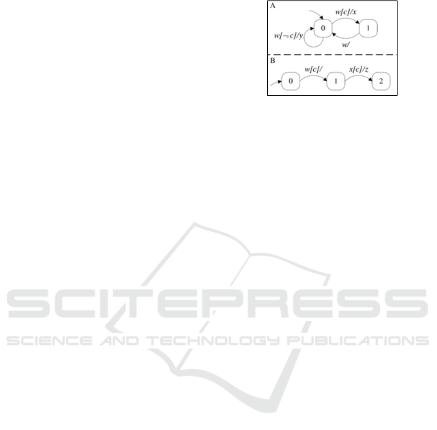
Fig. 1 (Chan et al., 2001) presents a simple example
with two parallel state machines A and B which are
synchronized using events. Arrows without sources
present the initial local states. Other arrows indicate
local transitions, which are identified with the form
trig[cond]/acts, where trig is a trigger event, cond is
an optional guarding condition, and acts is a
(possibly empty) list of action events. The guarding
condition is simply a predicate on local states of
other state machines and/or inputs to the system. The
general idea is that if the trigger event occurs and the
guarding condition either is absent or is evaluated to
true, then the transition is enabled. Initially, some
external events, along with some inputs from the
environment, arrive, marking the beginning of a
Figure 1: Statechart example.
step. The system leaves the source local states,
enters the destination local states, and generates the
action events (if any). The events are used to enable
some transitions as described above.
2.4 R-TNCES
An R-TNCES, as defined in (Zhang et al., 2013), as
a structure RTN=(B, R), where R is the control
module consisting of a set of reconfiguration
functions R = {r
1
,...,r
n
} and B is the behavior module
that is a union of multi TNCESs, represented as:
B = (P,T,F,W,CN,EN,DC,V,Z)
where: (i) P (respectively, T) is a non-empty finite
set of places (respectively, transitions), (ii) F
⊆
(P ×
T)
∪
(T × P) is a subset of flow arcs, (iii) W: (P ×
T)
∪
(T × P) → {0,1} maps a flow
arc to a weight, W(x,y) > 0 if (x,y)
∈
F, and W(x,
y)=0 otherwise, where x,y
∈
P
∪
T, (iv) CN
⊆
(P ×
T) (respectively, EN
⊆
(T × T)) is a subset of
condition signals (respectively, event signals), (v)
DC : F ∩ (P × T) →
{[l
1
,h
1
],...,[l|F∩(P×T)|,h|F∩(P×T)|]} is a subset of
time constraints on output arcs, where i
∈
[1,|F ∩ (P
× T)|],li,hi
∈
N, and li < hi, (vi) V : T
∨∧
→ {,}
maps an event-processing mode (AND or OR) for
every transition, (vii) Z = (M
0, D0), where M0 : P →
{0,1} is the initial marking and D
0 : P → {0} is the
initial clock position.
2.5 GR-TNCES
The formalism GR-TNCES was introduced recently
in (Khlifi et al., 2015). It is used to model and
control memory and energy resources of adaptive
probabilistic systems as well as discrete event
systems. A GR-TNCES is a network of R-TNCES
(Zhang et al., 2013). It is a structure G = ∑ R-
TNCES where R-TNCES = (B, R). R is the control
module consisting of a set of reconfiguration
functions {r
1
,…,r
n
} managed under memory and
energy controllers, and B is the behavior module
which is a union of multi TNCES (Zhang et al.,
Specification Approach using GR-TNCES: Application to an Automotive Transport System
107
2013), represented as follows: B = (P, T, F, QW, CN,
EN, DC, V, Z
0
) where:
(i). P (respectively, T) is a non-empty finite set of
places (respectively, transitions);
(ii). F is a set of flow arcs with F ⊆ (P × T) ∪ (T ×
P);
(iii). QW=(Q,W) where Q: F→[0, 1] is a real
number that represents the probability on the
arcs and W: (P × T) ∪ (T × P) →{0, 1} maps
a flow arc to a weight. Specifically, W(x, y) >
0 if (x, y) ∈ F, and W(x, y)=0 otherwise,
where x, y ∈ P ∪ T;
(iv). CN (respectively, EN) is a set of condition
(respectively, event) signals with CN ⊆ (P ×
T) (respectively, EN ⊆(T × T));
(v). DC: F ⊆ (P × T) → [l, h] is a superset of time
constraints on output arcs;
(vi). V: T→{∨, ∧} maps an event-processing mode
(AND or OR) to each transition;
(vii). Z
0
= (T
0
, D
0
) where T
0
: P → {0, 1} is the
initial marking and D
0
: P → {0} is the initial
clock position.
Each reconfiguration r is controlled by the controller
module R. It is a structure R consisting of a set of
reconfiguration functions {r
1
,…,r
n
}. A
reconfiguration function r is a structure
r = (Cond, Q, E
0
, M
0
, S, X), where:
(i). Cond: CN → {true, false}: the precondition
Cond of r can be evaluated to true or false and
can be modeled by external condition signals;
(ii). Q: F → [0..1]: TNCES probability which
could be a functional (internal to the TNCES)
or a reconfiguration probability. It is a new
parameter for GR-TNCES;
(iii). E
0
: P → [0..max]: controls the energy
requirements by the TNCES to the energy
reserves;
(iv). M
0
: P → [0..max]: controls the memory
requirements by the TNCES to the reserves;
(v). S: TN(•r) → TN(r•): is the modification
instruction of the reconfiguration scenario;
(vi). X: last state (•r)→ initial state (r•): is the state
processing function, where last state (•r)
(respectively, initial state (r•)) denotes the last
(respectively, initial) state of •r (respectively,
r•) before (respectively, after) the application
of r.
Let TN = P ×T ×F ×QW ×CN ×EN ×DC ×V be
the Cartesian product of all feasible net structures
that can be performed by a system. Let
•r
(respectively, r•) denotes the original (respectively,
target) R-TNCES before (respectively, after) the
reconfiguration function r is applied, where TN(
•r),
TN(r
•) ∈ TN. A state machine specified by an R-
TNCES, which is called Structure_changer, is
introduced to describe the control module. In this
state machine, each place corresponds to a specific
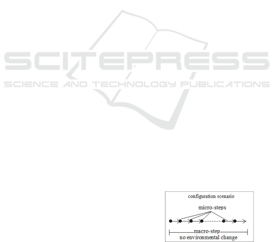
TNCES that refers to a configuration scenario. This
place can be introduced as a macro-step which is
composed of a set of micro-steps as shown in Fig. 2.
Initially, some external events along some inputs
from the environment arrive, marking the beginning
of a macro-step. The events may enable some
transitions. The system leaves the source local states,
enters the destination local states, and generates the
action events (if any). Unless they are regenerated
by other transitions, the events disappear after one
micro-step. The macro-step is finished if there is no
enabled transition. Each transition of the
Structure_changer corresponds to a reconfiguration
function. A place sp gets a token, which implies that
the TNCES to which sp corresponds is selected. If a
transition st (∀ st ∈ sp•) fires, then it removes the
token away from sp and brings it into a place sp’
with sp’ ∈ st•. Firing st implies that a reconfiguration
function is applied. Then, the TNCES is changed
into another one corresponding to sp’. The
Structure_changer is formalized as follows:
Structure_changer = (P, T, F, Q, E’, M’)
where ∀ t ∈ T, |•t| = |t•| =1, and only one TNCES is
performed at any time. Each place of this structure
contains the whole information about the
corresponding TNCES e.g. its energy and memory
requirements (number of states in this TNCES). Fig.
3 shows an example of a GR-TNCES model of four
R-TNCES. M and E design respectively the memory
and energy resources of each R-TNCES. Mem and
Eng are the memory and the energy reserve of the
control module
R. The parameter Q ∈ [0, 1] is the
corresponding probability for each R-TNCES
branch. It represents the chance to attend such a
scenario for unpredictable systems. Let ß be a
TNCES and Cost TNCES be the needed resources
by this TNCES. The states of a GR-TNCES are
defined as follows; A state of G is a pair (TN(ß),
State(ß)), where TN(ß) denotes the net structure of G
and State(ß) denotes a state of G. The evolution of a
GR-TNCES depends on what events, energy and
memory constraints take place. GR-TNCES deals
Figure 2: Macro-step, micro-step.
ICSOFT 2017 - 12th International Conference on Software Technologies
108
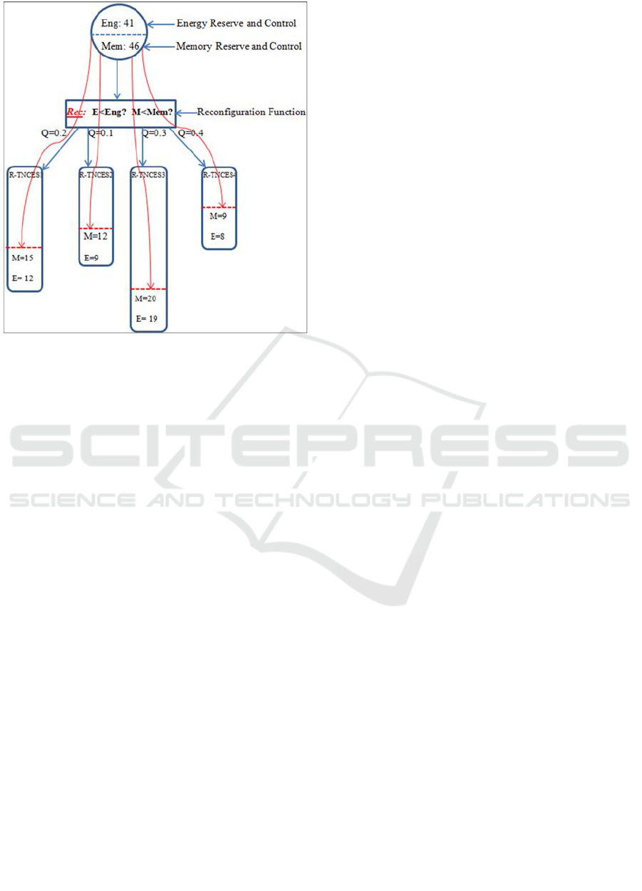
Figure 3: Example of a GR-TNCES architecture.
with the system’s reconfiguration. A reconfiguration
function r = (Cond, Q, E’, M’, S, X) is enabled at
state (TN(ß), State(ß)) if the following conditions are
met:
(i).
TN(ß) = TN(•r), i.e., TN(ß) is equal to the net
structure of •r and the firing time constraints
are valid,
(ii).
Cond = true: The reconfiguration’s
precondition is fulfilled,
(iii).
The energy and memory reserves can cover
the cost of that scenario,
The memory reserves M’ are enough: i.e., M’ > Cost
TNCES (M
0
). M
0
is removed from the memory
controller. Once this reconfiguration is finished,
these memory tokens are added back to the memory
reserve.
3 SPECIFICATION APPROACH
To analyze GR-TNCES using state-exploration
techniques, we have to deal separately with the
behavior and the control module of this formalism.
We view the control module as a transition system
(C, Rec, In) where C is a set of macro-steps or a set
of system configuration, Rec ⊆C×C a transition
relation or reconfiguration function. It is a labeled
function with the control property. It maps the
reconfiguration scenario to the respected constrains
(energy, memory, probability). In describes the
initial system configuration which should be a
standard defined configuration. So, the start point
will be static. The initial state will be described later
in the behavior model. The reconfiguration function
is assumed to be a tuple of the current configuration
(macro-step), the events and conditions occurring,
the desired probability, and the needed energy and
memory resources compared to the current storage.
At each reconfiguration scenario respecting to high
level strategy, the controller choose the maximal
probabilistic transition to be fired for the next step.
Rec
Max
≡ (E’ > Cost TNCES
Max
(E
0
)) ˄ (M’ > Cost
TNCES
Max
(M
0
)) ˄ ∩
e
∈
EN
e ˄ ∩
c
∈
CN
c (1)
which describes how macro-steps are selected: the
highest probabilistic scenario have to guarantee the
resource constraints related to energy and memory.
The events and conditions should also occur.
Otherwise they are considered to be true. For low
probability reconfiguration, the transition relation
will be introduced as:
Rec
Min
≡ (E’ > Cost TNCES
Min
(E
0
)) ˄ (M’ > Cost
TNCES
Min
(M
0
)) ˄ ∩
e
∈
EN
e ˄ ∩
c
∈
CN
c (2)
which describes how macro-steps are selected: the
lowest probabilistic scenario have also to respect
resource constraints related to energy and memory.
The events and conditions should also occur. If there
is no event, it is considered to be true.
Once the macro-step is selected, the system
should start the micro-steps of the fixed
configuration. We view the behavior module as a
transition system (P, R, I) where P is a set of global
states, R ⊆ P×P a transition relation. It is a labeling
function that maps each transition to the holding
properties in the corresponding transition, and I ⊆ P
a set of initial state. A transition in R is a tuple of the
current local state (system source state), the events
and conditions occurring, the probabilistic value of
the environment inputs and the time period in which
the transition could be fired. A path is sequence of
states that belongs to P. A state is reachable if it
appears on such trace path execution. We
symbolically encode the global state space P of a
GR-TNCES system by declaring a set Y of state
variables as follows: For each system state m,
declare a state variable ranging in the local states of
m. Given this encoding, the set of initial states I is
represented as:
I≡ ∩
m
∈
P
m≡ m
0
˄ ∩
e
∈
Ei
¬e ˄ ∩
c
∈
CNi
¬c ˄ (T
0
={1}) ˄
(D
0
={0}) (3)
where m
0
is the initial local state, Ei the set of
internal events and CNi the set of internal guarding
Specification Approach using GR-TNCES: Application to an Automotive Transport System
109

condition. This simply says that, initially, each
system is in its initial local state, all internal events
and guarding conditions do not occur, the state is
marked and the clock position is 0, but the condition
events are not constrained. The most important thing
is the encoding of the nondeterministic transition
relation R. Here we are considering the micro-step
transition. To illustrate the idea of the encoding, for
each state variable var ∈ Y, declare a variable var'
that has the same range as var and intuitively
represents its next-state value. Let Y
0
be the set of all
these primed variables. We would like to define an
expression over Y ∪Y
0
to specify the relation R. For
each local transition t, let src(t), dst(t), evt(t),
cond(t), time(t), mode(t), and prob(t), denote its
source local state, destination local state, trigger
event, guarding condition, and the firing time
interval, the firing mode{AND, OR}, and the firing
probability respectively. The expression evt(t) and
cond(t) are defined to be true if transition t does not
have a guarding condition and event inputs. Define
curr(t) to be the current state of the system in which
t is located and an expression enb
prob
(t) as:
enb
prob
(t) ≡curr(t) ˄ evt(t) ˄ cond(t) ˄ time(t) (5)
it represents whether the desired probabilistic
transition t is enabled: It is enabled when its trigger
event and guarding condition simultaneously occurs
and the current clock time respects the firing time
constraints if the firing mode is AND. We have also
the possibility to deal with other firing mode as it
described here:
enb
prob
(t)≡ curr(t) ˄ time(t) ˄ (evt(t) ˅ cond(t)) (6)
It presents how the transition t is enabled: It is
enabled if one trigger event or guarding condition
occurs and the current clock time respects the firing
time constraints of this transition once the firing
mode is OR. We assume that the system now is in a
configuration scenario, we want to describe how the
system moves in a micro-step. For each state m of
the system, we define micro
m
to describe how the
system state can progress during time:
micro
m
≡(∩
t/curr(t)=m
(enb
prob
(t)→curr'(t)=dst(t))) ˄
(∩
t/curr(t)=m
(¬enb(t)→curr'(t)=curr(t))) (7)
The first conjunct guides the system states from the
enabled transition to the destination state of an
enabled transition, while the second conjunct
prohibits the system from making any state change if
none of the transitions are enabled. Each fired
transition can generate some events. The generation
of events evt(t) and conditions cond(t) at each state
through the system execution are described
respectively as follows:
micro
e
≡ (∪
t/e
∈
Evt(t)
enb
prob
(t)) ↔ e' (8)
which present if an event is generated by the current
micro-step. It is derived from the union of enabled
transition that can send events to activate different
states of the system. Similarly, the micro-step
generates guarding condition. It is represented as:
micro
c
≡ (∪
m
/c
∈
Cnd(t)
micro
m
(t)) ↔ c' (9)
It is derived from the union of states that can be
guarding conditions to activate other different states
of the system. Then, we can introduce micro to
encode all the micro-steps in one macro-step. It is a
conjunction of micro states, micro events and micro
conditions.
micro≡∩
e
∈
CN
micro
c
˄ ∩
c
∈
EN
micro
c
˄ ∩
m
∈
P
micro
m
----------
(10)
The authors introduce an optimized specification
approach: it is useful to describe the system
requirements. It makes possible to deal with
unpredictable reconfiguration scenario, time
constraints, and limited energy and memory
resources.
4 TEST CASE: SKID CONVEYER
Skid conveyors are one type of transport systems
that are widely used in the automotive industry.
Transporting a body in the paint shop or transporting
chassis from one workstation to another in the final
assemblies are typical use cases. For this purposes,
we define an extended skid conveyor system showed
in Fig. 4, which will be one part of the automated
commissioning line in the “Zentrum für
Mechatronik und Automatisierungstechnik” (ZeMA)
in Saarbrücken, Germany. The following section
describes the functional requirements of the system.
Figure 4: CAD model.
4.1 Functional Requirements
The skid conveyor should consist of three conveyor
parts (Khlifi et al., 2016). Actually, there is an old
system where all the conveyor’s motors could be
only switched together and manually from one mode
ICSOFT 2017 - 12th International Conference on Software Technologies
110

Figure 5: Worker use cases.
to another operation mode. We aim to introduce new
functional modes. It should be possible to localize
the chassis on every part. In each conveyor part, the
chassis should stop for 7 seconds for other tasks by
various robots. In order to minimize the energy
consumption, every unused actor should be in a
standby mode or switched off. The purpose is to
reduce the consumed resources to move the car from
one skid position to the next one. For example once
the chassis is in the second conveyor part, the motor
of the first one should be switched off. The
activation/deactivation of the motors is controlled
with the help of the car position by the control
system. The worker should control the system with a
panel and Fig. 5 shows the possible uses cases.
4.1.1 Control
With this mode the worker can choose one operation
mode for the system. The requirements for these
operation modes are explained in the following part.
The system is reconfigurable. There are three
possible reconfigurations:
Automatic Mode: The worker should start and
stop this mode with the panel. The speed of the
skid should as well be controlled by the
worker. All other sensors and actors should run
automatically now. This means that first of all
the chassis position has to be clear. Then, the
chassis moves from one workstation to another
without user interaction. Since the position of
the chassis is logged, all unused actors can be
switched off. As soon as the chassis is at the
third position it should move backwards to the
start position and start again.
Manual Mode: In this mode the worker should
manually control all system functions. It should
be possible to start and stop all three conveyor
parts individually and together. It should be
possible to increase and reduce the speed of the
chassis.
Pause Mode: In order to save energy the
worker can activate and deactivate this mode
with the panel. If the mode is activated all
sensors and actors are switched off or change
to a standby mode.
4.1.2 Additional Information
If the worker uses this case all relevant sensor and
actor data should be visible. For example whether a
motor is on or off and the speed of the motor.
Settings: This mode should help the worker to
use the panel. It should be possible to increase
and reduce the contrast or to calibrate the
screen.
Diagnosis: If an error occurs the worker can
choose this mode. All sensor and actor errors
are displayed here.
4.2 System Encoding
The skid conveyor is supervised by a centralized
controller. It enables the reconfiguration and
switching mode from one configuration to a second
one. To simplify the use case specification, we
consider that the system is not probabilistic and that
the switching mode is chosen by the user of this
system to be denoted by RTN
skid
= {B
skid
, R
skid
}. Let
E
skid
and M
skid
be respectively the energy and
memory skid reserves. We use the proposed
specification approach to specify the system. Each
mode is represented by a macro-step. We identify
three macro-steps for the different modes: Rec1=
Macro1: Automatic mode, Rec2= Macro2: Manual
mode, Rec3= Macro3: Pause mode. This is a
reconfigurable system: it can change its behavior
from one mode to another mode. R
skid
is the control
module of the system. It is represented as:
R
skid
= Rec1 ∪ Rec2 ∪ Rec3
={
r
Rec1,Rec2
, r
Rec1,Rec3
, r
Rec2,Rec1
, r
Rec2,Rec3
,
r
Rec3,Rec1
, r
Rec3,Rec2
}
For example, the first reconfiguration: “r
Rec1,Rec2
”
implies that “•r”= “Rec1” and “r•”= “Rec2”. It
enables the switching mode from the current and the
next configuration of the system. Fig. 6 describes an
overview of the system model. It shows the possible
switching mode between all the macro-steps. The
initial state is the Idle position where the clock is
null and the initial marking exist. It could be
specified as follow:
I ≡
∩
m∈P
m
≡Idle˄
∩
e∈
E
i
¬e˄∩
c∈
CN
i
¬c ˄
(
T
0
={1}
)
˄
(
D
0
={0}
)
≡Idle
Specification Approach using GR-TNCES: Application to an Automotive Transport System
111
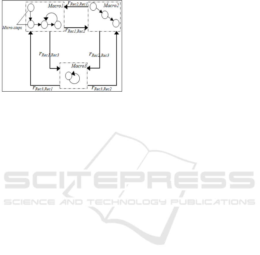
Figure 6: System model.
Then, according to the user choice, the system reacts
to the received command. Let EN
1
, EN
2
, EN
3
be
respectively the external events that activate Rec1,
Rec2, Rec3. These events are generated by the
system user. Marco1 is introduced as the
conjunction of the energy constraint condition, the
memory constraint condition and the trigger event
that will initiate the desired configuration.
Macro1≡
(E
skid
> Cost ‘Macro1’ (E0)) ˄ (M
skid
>
Cost ‘Macro1’ (M
0)) ˄ EN
1
.
The system keeps the same running mode till it
receives a trigger event from the user to change the
operational mode. The second reconfiguration is also
introduced as follow:
Macro2≡
(E
skid
> Cost ‘Macro2’ (E0)) ˄ (M
skid
>
Cost ‘Macro2’ (M
0)) ˄ EN
2
.
The system could switch for the third configuration
once its conjunctions are validated. This
configuration is introduced as followed:
Macro3≡
(E
skid
> Cost ‘Macro3’ (E0)) ˄ (M
skid
>
Cost ‘Macro2’ (M
0)) ˄ EN
3
.
Once the configuration is chosen the system starts to
execute the different internal tasks of that macro-
step. The behavior module of RTN
skid
is formally
described as follows: B
skid
= (P, T, F, QW, CN, EN,
DC, V, Z
0
) where the system network structure
TN
Maco1
, TN
Maco2
, TN
Maco3
∈ TN
skid
. We have P = P
1
∪
P
2
∪ P
3
, T = T
1
∪ T
2
∪ T
3
, F = F
1
∪ F
2
∪ F
3
, W = W
1
∪
W
2
∪ W
3
, CN = CN
1
∪ CN
2
∪ CN
3
, EN = EN
1
∪ EN
2
∪ EN
3
, DC = DC
1
∪ DC
2
∪ DC
3
, V (t) = V
1
(t) ∪ V
2
(t)
∪ V
3
(t), and ∀p
∈
P
1
∩ P
2
∩ P
3
, Z
0
(p)= z
0
1(p)=
z
0
2(p)= z
0
3(p).
Let’s focus on the behavioral module; we would like
to specify some system requirements of the model.
We are focusing on the first macro-step: (Macro1).
We aim to introduce some micro-steps of the target
macro-step. The authors start to introduce some
properties of the system. ‘It should be possible to
localize the chassis on every part of the conveyor’.
We note Pos
1enb
the micro-step that represent that the
car position is in the first skid part. We assume
curr(t) the system state that describes the position of
chassis. We focus on the case that the chassis should
be in the first position at a predefined time period
[a
1
,b
1
]. To detect that the chassis is in the suitable
location, the trigger events E
1.1
and E
1
.
2
should both
occur at that time period. We can formally introduce
this micro-state as:
Pos
1enb
≡ curr(t) ˄ E
1.1
˄ E
1
.
2
˄ time[a
1
,b
1
]
which evaluates the transition. This transition could
be enabled only if all the conjunctions of the
declared formula are validated. Regarding the
second position of the skid, it is formalized
respecting the same rules as follow:
Pos
2enb
≡ curr(t) ˄ E
2.1
˄ E
2
.
2
˄ time[a
2
,b
2
]
where E
2.1
and E
2.2
are the corresponding events to
detect that position, [a
2
,b
2
] is the time period for this
scenario. The system specification aims to save the
energy consumption of the system, i.e., the
corresponding motor for each conveyor part should
be off if there is no car at that moment. Let m
1act
(t)
be the active state of the first motor and m
2act
(t) for
the second motor. Here we define the rules of
m
2act
(t) as:
m
2act
(t) ≡ m
1act
(t) ˄ curr(t) ˄ E
2.1
˄ E
1.2
which represent that the active state of the second
motor is a conjunction of the active state of the first
motor, the presence of the chassis in the conveyor,
the occurrence of the E
1.2
: (chassis at the end of
conveyor 1) and E
2.1
: (chassis at the beginning of
conveyor 2). For the aim of saving energy the
system has to switch ON/OFF the motors according
to the position of the chassis. Once the second motor
is turned ON, the first one should be switched OFF.
We formalize the switching rules.
¬m
1act
(t) ≡ m
2act
(t) ˄ ¬curr(t) ˄ E
2.1
˄ ¬E
1.2
ICSOFT 2017 - 12th International Conference on Software Technologies
112
That represent that the deactivation of the first motor
is conditioned by the activation of the second motor,
the non-existence of the chassis in that skid which is
confirmed by the absence of the event E
1.2
and the
presence of the next event E
2.1
. The enabled
transitions can generate many events for the
synchronization and the interaction of the system
parts. Then, the micro event E
2.1
is generated through
the movement of the chassis from the first skid to
second one (curr(t) → curr’
enb
(t)). The formalization
is as follow:
micro
e
≡ (∪
t/e∈EN
1
(t)
curr’
enb
(t)) ↔ E
2.1
The authors present and clarify the specification of
the system requirements using the presented
approach. Once finishing, we move to the next step
which is: the modeling and simulation.
4.3 System Modeling
In this Section, we expose the automotive transport
system model. We model the system using GR-
TNCES formalism using the environment ZIZO
1
1
(Salem et al., 2015). It allows modular architectures
communicating using condition/event signals. The
tool ZIZO is developed as a collaboration between
Saarland University and Carthage University. It is
useful for the modeling and simulation of distributed
control systems. We model the system with aim to
save the consumed energy by proposing an optimal
control strategy of the chassis position in the skid.
The new model features additional sensors to
detect the position of the workpiece on the conveyor.
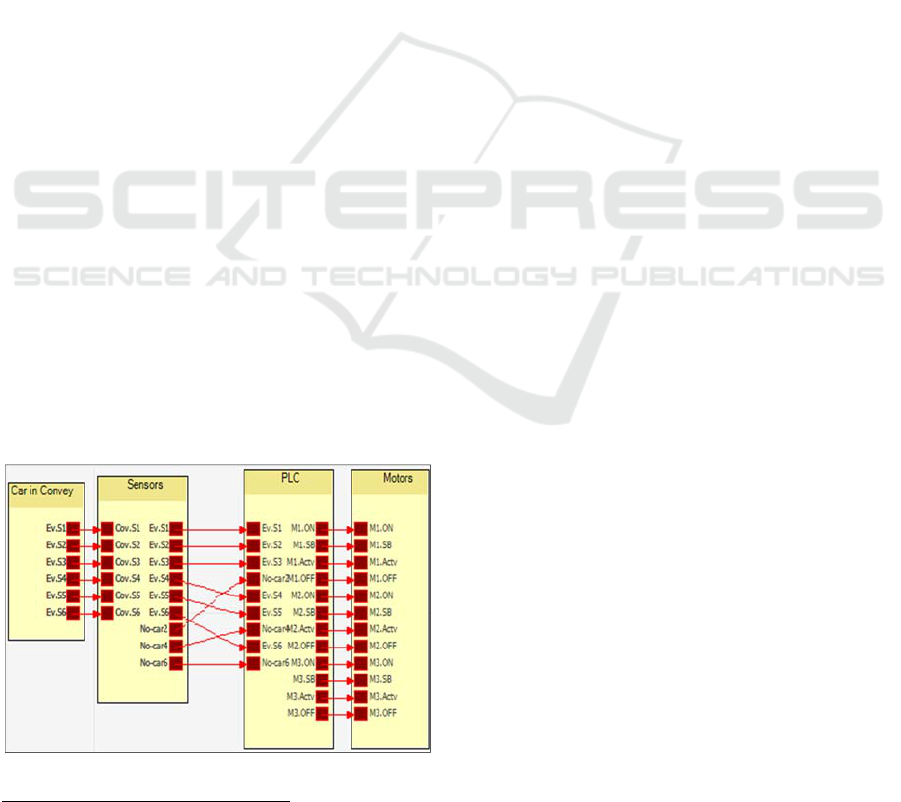
Fig. 7 describes the proposed model which is a
distributed discrete event system composed of four
modules: The car in the conveyor, the sensors, PLC
and the three motors. If the sensitive sensor detects
the entrance of a car in the conveyor, then it sends
Figure 7: Transport system model.
1
www.aut.uni-saarland.de/forschung/forschung-zizo-tool-khlifi/
an event signal to the PLC. It activates and
deactivates the corresponding motors according to
the car position in the conveyors. The first module
contains six events which correspond to the six
sensors installed in the three skid conveyor parts.
For the sensors module, it receives the events sent
by the conveyor then transfers them to PLC. It has
three extra-events denoted by “No-Car2”, “No-
Car4”, and “No-Car6” which correspond
respectively to events received from sensors number
two, four and six to notify the PLC about the car’s
availability. The third module corresponds to the
PLC module that controls the whole system. The
PLC receives signals from the sensors to control the
state of the motors (active, standby, off). The events
“M1.ON”, “M1.SB”, “M1.Act”, and “M1.Off”
correspond respectively to control the states of the
motors “Start, Standby, Active and Off”.
4.4 Simulation
To evaluate the energy optimization of the proposed
model, we refer to the old system. Thus, it is
possible to calculate the energy gain. We suppose
that the motor consumes four energy units (tokens)
per second in the running mode, one token in the
standby mode and zero unit if it is off. The
simulation results are shown in Fig. 8. The energy
consumption curves are showed during a simulation
time (30 seconds). This figure illustrates the
evolution of the token number needed by the system
in this period. We present the curves that describe
the proposed energy efficient mode’s consumption
on the right graph and the old model’s consumption
on the left. In the energy efficiency mode, usually
there is only one motor which is active. The idea is
based on the detection of the car position to activate
and deactivate the corresponding motors. The curves
present three horizontals parts. It corresponds to the
period in which the motors are deactivated in the old
model and the standby mode in the proposed model.
The other portions correspond to the motors’
activation period and the energy consumed by the
three motors to move the car from one position to
the next one. We notice that there is an important
reduction of the energy consumed in the proposed
model. For the first part (2-4 seconds), the
consumption is highly reduced (21 to 7 tokens) since
only one motor is activated instead of three motors
compared to the old model. To move the car to the
second position (16-19s), the proposed system
model consumed 26 tokens. On the other hand, the
basic model needs 44 energy units for the same task.
It is a valuable optimization. In fact, the sensors
Specification Approach using GR-TNCES: Application to an Automotive Transport System
113

Figure 8: Comparison of the consumed Energy.
detect the car position and the PLC controls the
activation and deactivation of the motors: It
deactivates the first motor and turn on the second
one. For the third part of the system, this strategy
enables us to save 22 energy units compared to the
basic plant model.
5 DISCUSSION
We proposed a new specification approach. It is
much more expressive and optimized compared to
statecharts used in symbolic model checking. The
aforementioned approach is distinguished from
statecharts by the ability of coping with
reconfigurable systems and time constraints. It is
possible to express more restrictions related to timed
systems and real time process. This approach could
describe systems that could change their behavior at
run-time process which are recognized as adaptive
systems. It is also possible to use deferent firing
mode for the system transition states: i.e., we can opt
from AND/OR mode according to the system
requirements. (AND if all the transition inputs are
required, OR is used if one them if enough). Thanks
to this formalism, it is possible to check resources
availability before starting such a reconfiguration
scenario. It is not possible to have resources
violation once the system executes its tasks because
it has already checks their availability. The concept
of unpredictable behavior is also coved here. The
specification approach is able to describe the
probabilistic behavior; the unpredictable
reconfiguration and tasks are both specified. We
present also a complete approach ranging from
specification, modeling to simulation of the
automotive transport system used as a case study.
6 CONCLUSIONS
Our work consisted, through this paper, in proposing
a new specification approach to specify and model
unpredictable flexible control systems running under
memory and energy resources constraints. The
proposed approach is based on the GR-TNCES
formalism. We introduced expressive method that
could deal with limited memory and energy reserves
at run-time processes which was not discussed in our
previous work. It is possible to express the
probabilistic reconfiguration scenario of such a
system and an optimal specification of the system
requirements. An automotive transport system is
used as a case study for specification, modelling and
simulation. The reconfigurations and the
functionalities of the system are specified thanks to
this approach. A new GR-TNCES model with aim to
save of the proposed system is implemented using
ZIZO. We simulate the new proposed model to
evaluate its energy consumption compared to old
system model. The reported result of the improved
system shows energy savings quite nicely. During
the next step of this project, we will work on the
validation of the proposed model through a real
energy data measurement of the skid conveyor.
ACKNOWLEDGEMENTS
This work was supported by Zentrum für
Mechatronik und Automatisierungstechnik” (ZeMA)
and “ERASMUS+ Program” at Saarland University
–promoted by the European Program. This research
work is a collaboration between Saarland University,
Germany and University of Carthage, Tunisia.
REFERENCES
Andrade, E., Maciel, P., Callou, G., and Nogueira, B.,
(2009). “A methodology for mapping SysML activity
diagram to time petri net for requirement validation of
embedded real-time systems with energy constraints”.
Proceedings of the 3
rd
Int. Conf. on Digital Society,
Cancun, Mexico, pp. 266-271.
Bastide, R., Buchs, D., (1998). “Models, Formalisms
and Methods for Object-Oriented Distributed
Computing”. Proceedings of Object-Oriented
Technologys, Berlin Heidelberg: Springer, pp221-255.
Bortolussi. L., et al., (2015). “Verification of Complex
Adaptive Systems”. [Online]. Available: http://home
page.lnu.se/staff/daweaa/papers/2015CASVerification.
pdf.
ICSOFT 2017 - 12th International Conference on Software Technologies
114

Chan. W., et al., (2001). “Optimizing Symbolic Model
Checking for Statecharts”. IEEE Transactions on
Software Engineering, vol. 27, no. 2, pp. 170-190.
Chen, Y. F., Li, Z. W., and Zhou, M. C., (2014). “Optimal
supervisory control of flexible manufacturing systems
by Petri nets: A set classification approach”. IEEE
Trans. Autom. Sci. Eng., vol. 11, no. 2, pp. 549-563.
El-kustaban, A., Moszkowski, B., and Cau. A., (2012).
“Specification Analysis of Transactional Memory
using ITL and AnaTempura”. Lecture Notes in
Engineering and Computer Science, pp. 176–181.
Harel, D., et al., (1990). “STATEMATE: A Working
Environment for the Development of Complex
Reactive Systems”. IEEE Transactions on Software
Engineering, vol. 16, no. 4, pp. 403-414.
Harel. D., (1987). “Statecharts: a visual formalism for
complex systems”. Science of Computer Programming
Vol 8, no 3, pp. 231-274.
Khlifi, O., Mosbahi, O., Khalgui, M., and Frey, G., (2015).
“GR-TNCES: New extensions of R-TNCES for
modeling and verification of flexible systems under
energy and memory constraints,” Proceedings of Int.
Conf. on Soft. Eng. and App, ICSOFT-EA, Colmar,
France, pp. 373-380.
Khlifi, O., Siegwart, C., Mosbahi, O., Khalgui, M., Frey,
G., (2016). “Modeling and Simulation of an Energy
Efficient Skid Conveyor using ZIZO”. Proceedings of
the 13
th
International Conference on Informatics in
Control, Automation and Robotics (ICINCO),
ISBN: 978-989-758-198-4, pp. 551-558, Lisbon,
Portugal.
Leveson, N. G., Heimdahl, M. P. E., Hildreth, H., and
Reese, J. D., (1994). “Requirements Specification for
Process-Control Systems”. IEEE Trans. Software
Eng., vol. 20, no. 9 pp. 684-707.
Ross, D., (1997). “Structured analysis (SA): A language
for communicating ideas”. IEEE Trans. Software
Engrg. pp. 16-34.
Salem, M. O. B., Mosbahi, O., Khalgui, M., and Frey, G.,
(2015). “ZiZo: Modeling, simulation and verification
of reconfigurable real-time control tasks sharing
adaptive resources: Application to the medical project
BROS”. Proceedings of the Int. Conf. on Health
Informatics, Portugal, pp. 20-31.
Wasserman. A., (1985). “Extending state transition
diagrams for the specification of human-computer
interaction”. IEEE Trans. Software Engineering.
Vol. 11 , no. 8, pp. 699-713.
Zhang, J., Khalgui, M., Li, Z.W., Mosbahi, O. and Al-
Ahmari, A. M., (2013). “R-TNCES: A novel
formalism for reconfigurable discrete event control
systems”. IEEE Trans. Systems, Man, and
Cybernetics: Systems, vol. 43, no. 4, pp. 757-772.
Zedan, H., Cau, A., Chen, Z., and Yang. H., (1999).
“ATOM: An object-based formal method for real-
timesystems”. Annals of Software Engineering 7, pp.
235–256.
Specification Approach using GR-TNCES: Application to an Automotive Transport System
115
