
Control Architecture Modeling using Functional Energetic Method
Demonstration on a Hybrid Electric Vehicle
Mert M
¨
ok
¨
ukc
¨
u
1,2
, Philippe Fiani
1
, Sylvain Chavanne
1
, Lahsen Ait Taleb
1
,
Cristina Vlad
2
and Emmanuel Godoy
2
1
Sherpa Engineering, R&D Department, 92250, La Garenne Colombes, France
2
Laboratoire des Signaux et Syst
´
emes (L2S, UMR CNRS 8506), Centrale Sup
´
elec - CNRS - Univ. Paris-Sud,
Universit
´
e Paris Saclay, 3 rue Joliot Curie, F-91192, Gif-sur-Yvette cedex, France
Keywords:
Control Design, Energy Management, Complex Systems, Modeling, Integrated Design, Systems Modeling,
Interconnected Systems, System-level Design, System Verification, Automotive Engineering, System
Architecture.
Abstract:
With the advances on component technology, communication and information, energy systems are becom-
ing more complex. In this context, energy optimization based on various criteria requires the development
of relevant and representative models that are able to characterize the system behaviour. Within this study,
functional modeling is used to represent a system at a higher level of abstraction, with simple equations, lo-
cal control loops and a decision manager (DM) for handling the energy flow. The reduced complexity and
fast simulation of this model simplify the validation of system architecture and components sizing, as well as
the performances evaluation of energy management algorithms according to different criteria. Once this first
validation is completed, the following step in the system design process is to test the same algorithms on a
more accurate model, represented at multi-physical level, that has its own local controllers and global resource
manager (GRM). One way to complete this second validation is to use the information computed using the
functional model, to design a high level controller of a more complex multi-physical model. To this purpose, a
solution is proposed to interconnect the two models, of the same system, that are represented at different level
of abstraction. First, it is shown how the GRM can be extracted from the functional model. Secondly, it is pre-
sented how this management system can be adapted in order to be used at multi-physical level. Both models
are developed for a plug-in parallel hybrid vehicle (PHEV), and the interconnection solution is illustrated for
the considered application.
1 INTRODUCTION
It is important to cite economic and ecological frame-
work that drags industry and researchers towards an
innovative energy management involving an associa-
tion of energy technologies, optimal control laws and
refined components. Along with the advancements
on component technology, communication between
them and obtaining information make systems more
intelligent. This growth of intelligence also makes
the system more complex. For energy systems, this
complexity hardens the work on energy management
and control strategies which enforces the research on
system engineering. The most important difficulties
on this subject are:
• Choosing the system architecture;
• Setting and sizing the system components;
• Optimizing the flow between multi-sources and
multi-consumers;
• Designing a control system architecture.
The goal of system engineering, as far as energy
systems are concerned, is to obtain optimal control
laws and energy optimisation. Increased complexity
and technology advancements on components drive
the research to evolve on modeling and simulation.
This research is made to design, identify and control
the system. All these challenges lead the system de-
velopers to research further on:
• A global and interactive approach to improve sys-
tematic innovation;
• A methodology for architecture evaluation and
system verification from the early stages of the
system life cycle;
• A system representation from multiple points of
view, in order to define and analyse the main ob-
Mokukcu, M., Fiani, P., Chavanne, S., Taleb, L., Vlad, C. and Godoy, E.
Control Architecture Modeling using Functional Energetic Method - Demonstration on a Hybrid Electric Vehicle.
DOI: 10.5220/0006413300450053
In Proceedings of the 14th International Conference on Informatics in Control, Automation and Robotics (ICINCO 2017) - Volume 1, pages 45-53
ISBN: 978-989-758-263-9
Copyright © 2017 by SCITEPRESS – Science and Technology Publications, Lda. All rights reserved
45
jectives;
• Design and identification of a control system.
For these reasons, including the tendency to de-
crease time −to − market, the complex system has to
be represented at a higher level of abstraction that will
ease its global understanding within a structured envi-
ronment. In the literature, this type of representation
is associated with systemic theory (Le Moigne, 1977).
Usually, physical models of complex systems have
been represented and analysed using Bond Graph
modeling and multi-domain simulation (Brunet et al.,
2005). However, another interesting approach is the
functional modeling (Penalva, 1994), (Suh, 1998),
(Mokukcu et al., 2016), which is based on the fol-
lowing principle: a system can be defined by basic
elements, modelled with an adequate level of com-
plexity, that faithfully describe the system behaviour.
By construction, Model Based System Engineer-
ing (MBSE) allows to specify and design systems at
different levels and to specify their elements and the
links between them. These links are: components and
information, requirements, architecture (functional,
multi-physical or otherwise), use cases and validation
tests (Fiani et al., 2016).
In (Fiani et al., 2016) and (Mokukcu et al., 2016),
three levels of modeling are introduced as:
• Teleological modeling: a system of missions fi-
nalized with respect to system environment, gov-
erned by regulations and standards;
• Functional modeling: the system of missions can
be defined by a set of key functions and the asso-
ciated architecture that realizes the missions;
• Multi-physical modeling: the key functions are
realized by a set of components and an equipment
usually provided by suppliers.
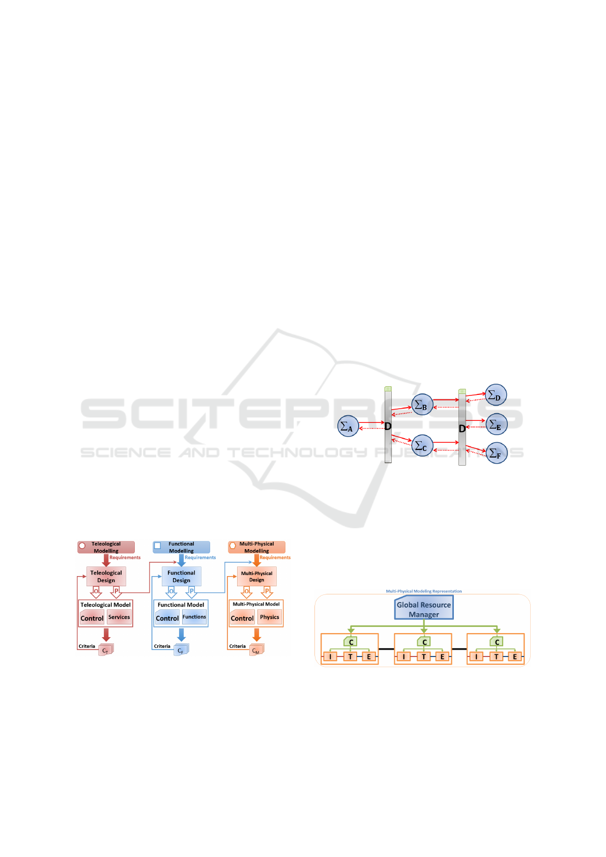
Figure 1: Multi level integrated design and simulation (Fi-
ani et al., 2016).
Fig. 1 illustrates the modeling steps for each sys-
tem representation at a different level of abstraction.
The development starts with requirements formula-
tion. Once the requirements are fixed, the parame-
ters (P) and objectives (O) are defined in order to ob-
tain a simulation model and its associated controller.
The evaluation of the resulting control system is per-
formed in simulation using validation criteria. If the
criteria are satisfied then the parameters of higher lev-
els of modeling will define the requirements of lower
levels of modeling. Otherwise, necessary modifica-
tions are made in the design process. This mecha-
nism helps to transmit objectives or parameters be-
tween different representations of the system. It can
be also found out that higher modeling levels become
cascade controllers for lower modeling levels (Fiani
et al., 2016).
At functional level of abstraction, the system be-
haviour is represented from an energetic point of
view, using simple equations that allow reducing the
amount of time needed to complete a simulation. The
functional modeling methodology and its semantics
(Mokukcu et al., 2016), (Fauvel et al., 2014), (Fau-
vel, 2015) are based on a FU (Functional Unit), also
referred as OFS (Organico-Functional Set) approach.
In Fig.2, the representation of a functional model is
given. Each element
∑
represents a functional unit
while D elements are used for energy distribution.
Figure 2: Functional modeling representation.
However, at multi-physical level, the system can
be represented as a composition of controlled sub-
systems (Mokukcu et al., 2016). The block diagram
of a multi-physical representation is shown in Fig. 3,
where C, I, T and E denote the local controller,
input conditioning, trans f ormer and e f f ector, re-
spectively. The GRM block acts like an energy man-
agement system for the multi-physical model.
Figure 3: Multi-physical modeling representation.
Indeed, in the early stages of the design process,
a functional model is preferred to represent the com-
plex system in order to validate (by fast simulations)
the system architecture and components sizing, and
ICINCO 2017 - 14th International Conference on Informatics in Control, Automation and Robotics
46

also to evaluate the performances of local controllers
and energy management strategies for different mis-
sions using different criteria. Naturally, the following
stages in the system design process is to test the su-
pervision and control algorithms that have been de-
veloped using the functional model, on the multi-
physical model. In Fig. 4, the control architecture is
illustrated at functional and multi-physical levels of
abstraction. On the left side of the figure, the sys-
tem is represented at functional level and the energy
flow within the system is managed by the supervi-
sion block DM using optimisation algorithms. On the
right side, C is a composition of local controllers of
the system, and P includes the physical subsystems.
Therefore, the main difficulty is to obtain the global
resource manager (GRM) of the multi-physical model
using information provided by local controllers and
decision manager (DM) of the functional model.
Figure 4: Control system representation.
The struggle of this extraction is given by: which
input/output of which physical subsystem should be
measured/estimated, how to use these signals to pro-
vide energy transfer information to functional model,
and after processing this information, how to trans-
form the computed power flow reference into a phys-
ical reference signal and transfer it to all different
types of controllers of physical subsystems.
For a better understanding of these challenges in
the context of an energy system, a hybrid electric ve-
hicle (HEV) is considered as an example of a multi-
source/multi-consumer system.
In this work, the issue of interconnecting the func-
tional and multi-physical models is presented, and a
solution is proposed showing how the GRM can be
extracted from the functional representation and be
connected to local controllers of the multi-physical
model. In Section 2, the multi-physical and functional
modeling methods are briefly introduced. In Sec-
tion 3, the interconnection procedure between the two
modeling levels is discussed. Section 4 presents both
models for a plug-in parallel hybrid vehicle, along
with the multi-physical model obtained as a result of
interconnection. Its performances are tested in simu-
lation for a specific mission. Conclusions and future
works are summarized in Section 5.
2 MODELING METHOD
REMINDERS
This section introduces briefly the multi-physical and
functional modeling methods, which are further ap-
plied to model the behaviour of a gear motor group at
multi-physical and functional level, respectively.
2.1 Multi-physical Modeling
Multi-physical modeling aims to represent the archi-
tecture of technological equipment. Generally in in-
dustry the 0D-1D multi-physical modeling is used
for a complex system to optimise its sizing, for con-
trol laws design and validation. This multi-physical
model allows representing the complex system as a
whole and is used for simulations, analysis and pre-
diction of system performances.
The multi-physical model is composed by ana-
lytical models that provide an accurate description
of the multi-physical behaviour of the complex sys-
tem. The multi-physical model can be developed un-
der the simulation environment Matlab/Simulink us-
ing a component-based approach derived from the
Bond Graph methodology. It is a language that allows
the passage between physical and mathematical mod-
els using a block-diagram environment (Brunet et al.,
2005). On the other hand, the simulation tool is based
on a multi-port concept: a unique link is used to rep-
resent and simulate all the interactions between dif-
ferent components. In the multi-physical methodol-
ogy, this link is represented by energy transfer. More-
over, every link between physical model components
consists of a flux variable and an effort variable that
depend on the physical domain. In Fig. 5, some ex-
amples are given for different domains. Despite the
advantages of multi-physical modeling (accuracy and
intermediate signals availability), the model design,
its simulation and validation are time consuming and
require expertise.
Figure 5: Multi-physical domains.
For these reasons, it is necessary to use a model
of a higher level of abstraction, which does not need
the definition of multi-physical elements, in order to
easily evaluate the system in the early stages of the
design process.
Control Architecture Modeling using Functional Energetic Method - Demonstration on a Hybrid Electric Vehicle
47
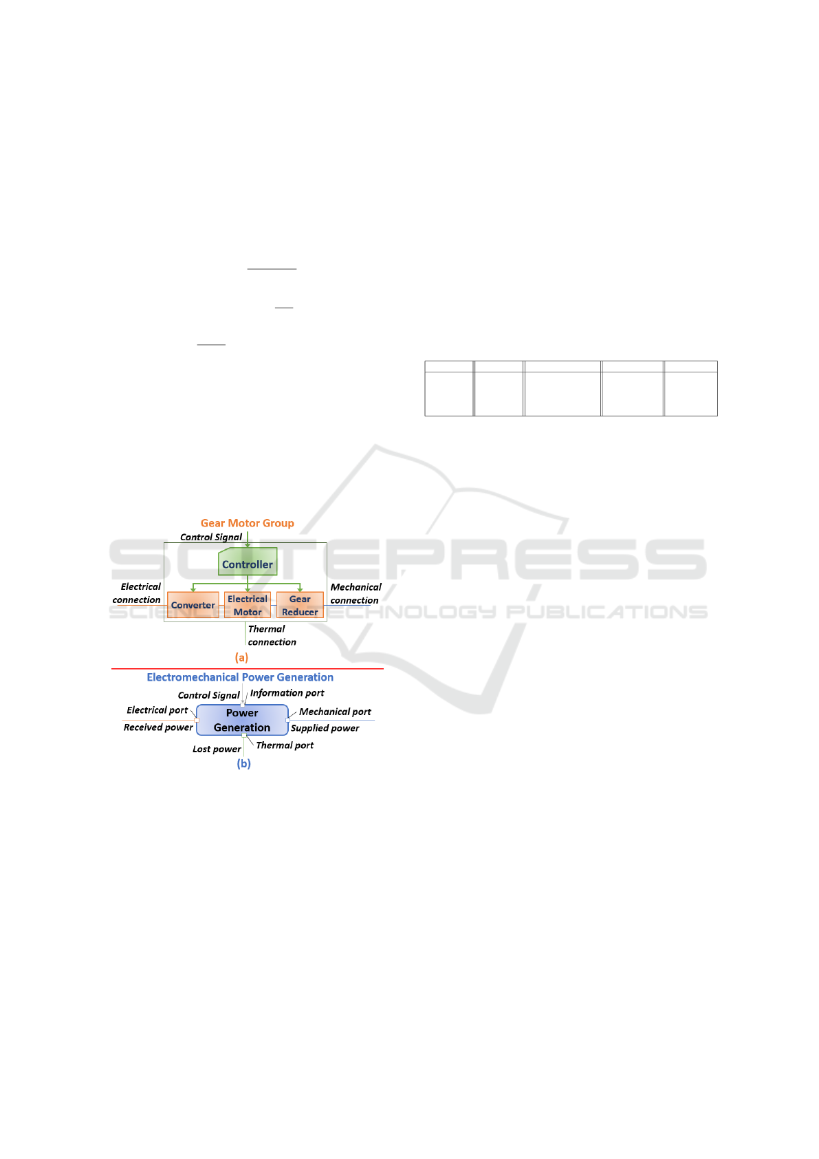
An example of multi-physical model for a gear
motor group is given in Fig. 6(b). The transformation
of electrical flow into mechanical flow is done using
a converter (1), an electrical motor (2), (3) and a gear
reducer (4), along with their local controller. For this
example, the physical behaviour of each component is
represented by a simple analytical model as follows:
u
R
= u
E
·
t
on
t
on
+ t
o f f
. (1)
u
R
= R
R
· i
R
+ L
R
·
di
R
dt
+ E. (2)
J
CR
·
d
2
θ
m
dt
2
= τ
em
− τ
p
− τ
ext
. (3)
τ
ext
= α · τ
out
. (4)
where u
R
denotes the rotor voltage; u
E
is the con-
verter supply voltage; t
on
/t
o f f
is the converter on/off
time; R
R
, i
r
, L
R
is the resistance, current and induc-
tance of the rotor, respectively; E is the electromotive
force; J
CR
is the inertia; θ
m
is the motor angular posi-
tion; τ
em
is the electromagnetic torque, τ
p
is the loss
torque; τ
ext
is the motor output torque; α is the gear
constant and τ
out
is the gear output torque.
Figure 6: Multi-physical (a) & functional (b) model repre-
sentations.
2.2 Functional Modeling
The concept of functional modeling has been intro-
duced and detailed in our previous work (Mokukcu
et al., 2016). Unlike multi-physical modeling con-
cept, in this methodology, functional links are em-
ployed to represent flow exchanges within the com-
plex system. In a functional model, the flow can be ei-
ther energy, either matter or both, and it is exchanged
together with an information flow. The exchange of
flow is made between five types of elements (source,
storage, distribution, transmission and effector), each
of them having source and consumer ports. Source
ports receive expressed need from consumer ports and
they answer by supplying the requested need. In ad-
dition, consumer ports transmit demands of need to
source ports. This gives the method its modularity.
Brief information about the basic elements of func-
tional modeling is given in Table 1. The functional
model can be simulated using the Matlab/Simulink
simulation environment with a functional modeling li-
brary, which contains all this basic elements.
Table 1: Element types of functional energetic modeling
and associated functions (Mokukcu et al., 2016).
Source Storage Transformation Distribution Effector
Energy &
Matter
Source
Energy &
Matter
Storage
Energy & Matter
Transformation
in Different
Domains
Energy &
Matter
Distribution
Represents
Energetics
Services
In a functional model, the need computation starts
from the effector. For example, the need of energy for
a plus-in hybrid electric vehicle (PHEV) is calculated
by electrical auxiliary element or vehicle dynamics el-
ement (both of them effectors of the system). Then,
the energy need is transmitted to storages or sources
via distribution and transformation elements. Based
on information flow, the storages and sources can de-
cide whether they are able to provide the requested
energy or not. Furthermore, distribution elements are
used to manage the energy flow between sources and
storages, and to supply the requested energy to ef-
fectors as an answer to their need. If a hotel water
treatment system is considered, the need of water con-
sumption is calculated by hotel consumer element (ef-
fector) and the hotel logistics element must supply the
required amount of water, with suitable properties.
Fig. 6(a) illustrates an example of a functional
model, which also represents an energy transforma-
tion (electrical energy into mechanical and thermal
energy) but without considering the real physical be-
haviour. The model is described as below:
P
mech
= η · P
el
(5)
where P
mech
denotes the mechanical output power,
P
el
is the electrical input power and η is the effi-
ciency. Besides (5), maximum and minimum power
limitations, P
min
and P
max
, are specified for each func-
tional element. Moreover, these elements include the
dynamic behaviour of the functional units. The dy-
namic behaviour is taken into account either by an in-
tegration for the energy-to-power transition, either by
adding 1
st
(or 2
nd
) order transfer functions of the dif-
ferent elements such as transformations, storages or
effectors.
ICINCO 2017 - 14th International Conference on Informatics in Control, Automation and Robotics
48

The functional model allows fast simulations for
system evaluation (sizing, architecture, requirements
management) before choosing the technology, obtain-
ing the GRM of multi-physical model and simulating
the system as a whole. In the next section, the in-
terconnection between functional and multi-physical
modeling is presented, which comes to extract the
GRM from the functional model.
3 INTERCONNECTION
BETWEEN FUNCTIONAL AND
MULTI-PHYSICAL MODELING
Functional modeling defines key-functions (FUs), al-
locates and refines end-mission requirements to the
FUs and also defines the energy management system.
On the other hand, multi-physical modeling defines
the physical architecture or physical units, allocates
and refines the functional requirements to physical
units. To overcome the challenges associated with the
control laws design and energy management within
the entire system, functional and multi-physical mod-
els are interconnected. In this section, the difficulties
related to the interconnection are presented along with
the proposed solution. This solution is presented for
the gear motor group and the electromechanical en-
ergy transformation that are introduced as examples
in Section 2.
3.1 Problems of Interconnection
As presented in Fig. 4, the functional modeling level
includes a control strategy that will be used by the
control system of the multi-physical model. More-
over, this strategy is independent from technical com-
ponents, and is defined according to the decision man-
ager allocated from end-missions model.
In Fig. 7, a representation of control systems and
Figure 7: Control system and flow exchange representations
of functional and multi-physical modeling.
flow exchanges of functional and multi-physical mod-
els is shown, for a battery electric vehicle (BEV).
Here, the challenge is to find the adequate language
to connect both models.
As flux exchanges are different between func-
tional and multi-physical models, the connection can-
not be done directly. Since multi-physical model
components need physical domain references and
functional model components require a power de-
mand reference for simulation, connecting the power
flow to physical domain flows can be a challenging
task. At this stage, the interesting features of the in-
terconnection can be expressed as follows:
• Functional modeling allows fast control archi-
tecture design and fast adaptation to eventual
changes in the system,
• Multi-physical representation is too complex and
time consuming when trials are accomplished.
3.2 Proposed Solution
A solution to the interconnection problem is to build
an interface between the multi-physical and func-
tional model. As illustrated in Fig. 8, this interface
contains passage equations between physical domain
and functional domain. It accomplishes the following
functions: determine the equivalent physical refer-
ences required for the multi-physical model based on
the power demand provided by the functional model;
measure/estimate the power supply that the system
is able to deliver using information from the multi-
physical model, and transfer the estimated power sup-
ply to the functional model. For each functional
model element, an interface is required in order to cal-
culate/adapt the necessary values.
If the electromechanical transformation element is
considered, the interface between this element and
Figure 8: Functional to multi-physical domain interconnec-
tion.
Control Architecture Modeling using Functional Energetic Method - Demonstration on a Hybrid Electric Vehicle
49

electrical propulsion group (drive and electric ma-
chine in this example) uses the following equations:
P
∗
f nc
|
b
ω
r
|
= τ
∗
cns
. (6)
P
mech
=
b
P
f nc
. (7)
where P
∗
f nc
denotes the power demand; |
b
ω
r
| is esti-
mated/ measured angular speed of rotor; τ
∗
cns
is torque
demand; P
mech
is calculated mechanical power of the
electrical machine and
b
P
f nc
is estimated/measured
output power of the motor.
In the next section, an example of PHEV is pre-
sented. First of all, model architectures of functional
and multi-physical models are given, and secondly,
simulation results using the functional model and the
multi-physical model with GRM are discussed.
4 APPLICATION EXAMPLE:
HYBRID VEHICLE ENERGY
MANAGEMENT SYSTEM
4.1 Motive
In a hybrid electric vehicle (HEV), and internal com-
bustion engine (ICE) and one or several additional
electric motors (EMs) are used for the vehicle pow-
ertrain. The ICE is supplied by fuel while the
EMs are supplied by a battery. These components,
usually allowing different possible interconnections,
form a complex and challenging multi-source/multi-
consumer system in terms of optimal control design
and energy management. Both objectives of the de-
sign process have to satisfy several vehicle services
like fuel consumption or comfort level. Although
there are optimization methods applied on HEVs,
they are implemented for a specific architecture of the
HEV and they usually require a priori knowledge of
the driving cycle. Thus, the problem is how to manage
the power split that globally satisfies the vehicle ser-
vices whenever the vehicle has a new task (Sciarretta
and Guzzella, 2007) and/or the system architecture is
reconfigured.
In this study, a parallel plug-in hybrid electric ve-
hicle (PHEV) is considered due to the resemblance to
a battery electric vehicle that has been highly investi-
gated over the last few years.
4.2 Control Architecture
The functional model of the parallel plug-in hybrid
vehicle has been developed in our previous work
(Mokukcu et al., 2016). The developed model, shown
in Fig. 9, is used to compute the power split bewteen
the multiple sources of the system, for different con-
figurations and missions of the vehicle. Moreover, it
allows to evaluate the fuel consumption, maximum
speed, maximum acceleration and regenerative brak-
ing power (Mokukcu et al., 2016).
Figure 9: Functional model of PHEV (Mokukcu et al.,
2016).
Thereafter, the next step in the design process is to
use the information provided by the functional model
(i.e. power signals for each source) for control de-
sign of a more complex multi-physical model. To this
purpose, the power signals are transformed into phys-
ical reference signals using an unique interconnection
element, which is added to each element of the func-
tional model to adjust the flow nature, as shown in
Fig. 10. Using this link, the functional and multi-
physical models are able to exchange necessary val-
ues of power or physical references, as well as mea-
sured/estimated values.
Figure 10: Functional model of M2E transformation ele-
ment with its connection element.
The multi-physical model of the system is given
in Fig. 11, where each component is a system itself.
For example, Fig. 12 illustrates the representation of
the electric machine subsystem.
As it can be noticed, the system architectures are
similar in both functional and multi-physical models.
Thus, if there is any change at multi-physical level,
the functional model has to be adapted respectively.
ICINCO 2017 - 14th International Conference on Informatics in Control, Automation and Robotics
50

Figure 11: Multi-physical model of HEV.
Figure 12: Electric machine component group.
4.3 Simulation Results
The simulations are run under the following assump-
tion: the vehicle always moves forward. The model
parameters are consistent with those of a parallel
PHEV available on the market. Table 2 provides the
technical characteristics of the vehicle.
Table 2: Technical characteristics of PHEV.
Technical Characteristic Value
Fuel tank max. volume 45 l
ICE max. output power 70 kW @ 5000 rpm
ICE max. output torque 140 Nm @ 4500 rpm
Battery voltage 210 V
Battery capacity 50 Ah
EM max. output power 60 kW
EM max. output torque 200 Nm
Combined max. output power 100 kW
Vehicle curb mass 1500 kg
Vehicle SCx (Aerodynamic drag coeff.) 0.63
Vehicle wheel radius 0.635 m
To be able to compare the simulation results with
the manufacturers brochure, the vehicle performance
indicators are determined and their values are given in
Table 3.
Table 3: Performance indicators of PHEV.
Performance data Value
Combined consumption (WLTC cycle) 3.2 l/100 km
Electric drive range 25 km
Vehicle max. speed 180 km/h
Vehicle max.speed in e-drive mode 85 km/h
Vehicle max. acceleration (0-100km/h) 11.4 s
First of all, the functional model with its DM is
simulated using the WLTC (Worldwide harmonized
Light vehicles Test Cycle) that yields the vehicle
speed and the power demand illustrated in Fig. 13
(a), (b). In addition, the DM uses a ruled-based en-
ergy management strategy based on priorities, which
is implemented in the distributor elements of the func-
tional model. In this example, the functional model
has three main distributors that are detailed in Table 4
with their priorities.
Table 4: Distributor priorities.
Priority No Distributor 1 Distributor 2 Distributor 3
1 Drive Electrical Aux Electric Drive
2 Battery Charge Drive Fuel Drive
3 N/A N/A Brake System
Distribution 1 transmits mechanical energy sup-
ply from fuel to mechanical transformation element
to drive or mechanical to electrical transformation el-
ements. Distribution 2 transmits electrical storage en-
ergy supply to electrical auxiliary or drive. Distribu-
tion 3 transmits the energy need of vehicle dynamics
to electric drive supply element or to fuel drive supply
element or to the brake system.
The obtained results are also shown in Fig. 13.
The vehicle speed and power achieve the desired pro-
files and meet the requirements of the WLTC. The
regenerative braking can be observed between 1600s
and 1800s in the Fig. 13 (c), (d). We remark that
the vehicle speed on electric drive is limited to 85
km/h and the electrical storage/battery SOC (state of
charge) is limited to %20; beyond these values, the
electric drive is abandoned and electrical energy is
consumed just by electrical auxiliaries.
Figure 13: Parallel PHEV - simulation results using the
functional model (Mokukcu et al., 2016).
These results represent a first validation of the
chosen architecture of the vehicle and of the energy
management strategy used to handle the power split
within the system. However, at this level of abstrac-
tion, the energy model cannot generate specific phys-
ical signals such as electric motor output torque or
Control Architecture Modeling using Functional Energetic Method - Demonstration on a Hybrid Electric Vehicle
51

battery output current.
Simulation results of the multi-physical model
and the proposed control arhitecture are illustrated in
Fig. 14.
Figure 14: Parallel PHEV - simulation results using the
multi-physical model with GRM.
According to Fig. 14, the following remarks can
be made:
• Vehicle power need pattern is compatible with al-
located source powers;
• When the vehicle surpasses 85 km/h (Fig. 14 (c))
the source power allocation moves to fuel source
power, but at the same time battery SOC decreases
(Fig. 14 (d)). The reason behind this is the con-
stant electrical auxiliary load;
• A slight increase in battery SOC is seen at the end
of the simulation showing the regenerative brak-
ing effect;
• Based on the parameters values shown in Table 2,
the results are consistent with the physical limits
of the components;
• From the acquired data, the fuel consumption can
be calculated from following equation:
4SOC
Fuel
4d
· vol
Fuel
· 100 (8)
For this test scenario (WLTC), the obtained fuel
consumption is of 3.5l/100km. This result is
well approximated by the value given in Table 3
(3.2l/100km). Besides the fuel consumption, power
need and supply patterns have been compared. Slight
differences can be observed due to the system dy-
namic behaviour, especially at time instants with neg-
ative power supply.
With the proposed solution, the system can be ex-
amined globally but also locally. Each component of
the vehicle can be investigated separately if the simu-
lation model permits. Fig. 15 shows the electric ma-
chine results.
Figure 15: Hybrid vehicle electric machine results.
From the specific physical signals of the electric
motor, the following comments can be made with in-
formation that is given in Table 2:
• Output torque values of electric machine are
within its physical limits (maximum output torque
is 200 Nm);
• The angular speed of the electrical machine fol-
lows the vehicle speed with a certain gear ratio;
• The electric motor current is between the physical
limits with possibility of detailed analysis for re-
generative braking (for example motor K
t
(motor
torque constant) value is approximately 1, which
is acceptable);
• The electric motor mechanical power is illustrated
in order to calculate the motor and generator effi-
ciencies.
These results highlight the advantages of a multi-
physical model with a GRM: detailed analysis of
components, better precision and, therefore, reliable
validation of simulations. Other physical components
(ICE, auxiliaries, battery etc.) can also be analysed
using the same simulation data. However, data ex-
ploitation depends on the multi-physical model com-
plexity.
4.4 Additional Comments on
Reconfiguration
A major advantage of the functional model is the
ability to handle the system architecture reconfigura-
tion without reviewing the analytical modeling, which
cannot be avoided for a multi-physical representation
of the system. If a component is added or removed,
ICINCO 2017 - 14th International Conference on Informatics in Control, Automation and Robotics
52

the new configuration can be validated in a fast and
efficient way. An example of this interesting feature
is demonstrated in Fig. 16, highlighting the modular-
ity of functional modelling. Compared to Fig. 9, an
additional component is added to the system: a sec-
ond electric machine used for traction.
Figure 16: Reconfigurated HEV model.
Therefore, with faster simulations compared to
multi-physical modeling and ease of reconfigura-
tion, the functional modeling becomes a very useful
methodology for system modeling and simulation.
5 CONCLUSION AND FUTURE
WORK
In the presented work, a methodology of modeling a
control architecture was proposed using a functional
energy-based approach. The methodology was ap-
plied to a PHEV with WLTC use case, using Mat-
lab/Simulink simulation environment. The intercon-
nection between functional model and multi-physical
model serves to add a high level control to the multi-
physical system representation. At functional level of
abstraction, where the energy system exchanges need
and supply, the energy management algorithms are
easier and faster to adapt at this level of representa-
tion. Based on the functional model, the proposed
concept simplifies the control design and computes
appropriate multi-physical reference signals for the
multi-physical model.A first perspective of the pro-
posed modeling methodology is to establish a gener-
alized method to interconnect the two levels of mod-
eling.
Also, the simulated multi-physical model does not
contain gear box for the ICE. The components (ICE or
EM) models can be acknowledged as simple, which
means that the dynamic behaviour of the system and
its components cannot be thoroughly researched.
Future works intend to enhance the accuracy of
multi-physical model (by improving the components
models or by adding additional ones) in order to have
a more reliable validation. On the other hand, robust-
ness of the control architecture will be further investi-
gated.
Another perspective is to improve the energy man-
agement strategy used at functional level: more effi-
cient algorithms for need/supply distributions should
be developed and integrated into the simulation mod-
els for further validation. In this work, distributors
use priorities for power need/supply distribution. For
an optimal power split, an otimization-based energy
management algorithm should be used.
Finally, the proposed method for control architec-
ture design will be tested on different types of appli-
cations that need an optimal energy management like
water treatment systems or building energy manage-
ment systems.
REFERENCES
Brunet, J., Flambard, L., and Yazman, A. (2005). A hard-
ware in the loop (HIL) model development and im-
plementation methodology and support tools for test-
ing and validation car engine electronic control unit.
Lecce, Italy. International Conference on Simulation
Based Engineering and Studies, TCN CAE.
Fauvel, C. (2015). Approche modulaire de l’optimisation
des flux de puissance multi-sources et multi-clients,
´
a
vis
´
e temps reel. PhD thesis, Nantes, France.
Fauvel, C., Claveau, F., and Chevrel, P. (2014). Energy
management in multi-consumers multi-sources sys-
tem: a practical framework. pages pp.2260–2266,
Cape Town, South Africa. IFAC World Congress.
Fiani, P., Taleb, L. A., Chavanne, S., and Mokukcu,
M. (2016). Mod
´
elisation pour la conception et
l’
´
evaluation de syst
`
emes complexes. Revue Ing
´
enieurs
de l’automobile, vol.841.
Le Moigne, J. (1977). La th
´
eorie du syst
`
eme g
´
en
´
eral,
th
´
eorie de la mod
´
elisation. PUF, Paris, France.
Mokukcu, M., Fiani, P., Chavanne, S., Taleb, L. A., Vlad,
C., Godoy, E., and Fauvel, C. (2016). A new con-
cept of functional energetic modelling and simulation.
pages pp.536–541, Oulu, Finland. The 9th Eurosim
Congress on Modelling and Simulation.
Penalva, J. (1994). Sagace: la mod
´
elisation des system
`
es
dont la ma
ˆ
ıtrise est complexe. volume vol.94, pages
pp.536–541, Montpellier. 2nd International Confer-
ence on Integrated Logistics and Concurrent Engi-
neering (ILCE).
Sciarretta, A. and Guzzella, L. (2007). Control of
hybrid electric vehicles. IEEE Control Systems,
vol.27:pp.60–70.
Suh, N. (1998). Axiomatic design theory for sys-
tems. Journal of Research in Engineering Design,
vol.10:pp.189–209.
Control Architecture Modeling using Functional Energetic Method - Demonstration on a Hybrid Electric Vehicle
53
