
Multicast Algebraic Formal Modelling using ACP
Study on PIM Dense Mode and Sparse Mode
Pedro Juan Roig, Salvador Alcaraz and Katja Gilly
Department of Physics and Computer Architecture, Miguel Hernández University,
Avda. Universidad, s/n – 03202 Elche (Alicante), Spain
Keywords: ACP, Formal Protocol Specification, Multicast, Networking.
Abstract: Video streaming is becoming ever important regarding Internet traffic running on either fixed or mobile
networks worldwide. A great stake of that traffic is transferred by means of multicast in order to optimise
network resources and one of the most popular protocols aimed at multicast communications is called
Protocol Independent Multicast (PIM). This paper focuses on building up some models for its most common
types, this is, PIM Dense Mode and PIM Sparse Mode, by using manual algebraic derivations, following the
Algebra of Communicating Processes (ACP) axioms. The purpose of such models is to achieve a simplified
approach, yet as close to specifications as possible, to PIM dynamics for the different scenarios presented.
1 INTRODUCTION
Network communications using IPv4 may be
classified into three types, according to the number of
senders and receivers taking part in it. Unicast
transmission is the most commonly used, which
applies in case there is just one source and one
destination, whereas broadcast transmission refers to
one source to all destinations within a subnet.
However, multicast transmission describes
communications from one or more sources to a set of
destinations. That is why multicast streams enable
group-oriented applications, thus making information
delivery more efficient. Nowadays, their main
applications are related to audio and video
conferencing, but they are also used in selective
software distribution and dynamic groups.
Multicast routing protocols are necessary in order
to route multicast traffic through different networks.
The most popular of them is Protocol Independent
Multicast (PIM), which is a family of protocols
optimised for different environments.
PIM is considered an independent protocol
because it does not build up a multicast routing table,
but it relays on the unicast routing table, regardless of
which protocol was used to do so. PIM has two main
types, namely PIM Dense Mode (PIM–DM) (RFC
3973, 2005) and PIM Sparse Mode (PIM–SM) (RFC
7761, 2016), both having an opposite approach as to
how the devices inside a multicast domain behave.
In addition to the use of PIM among network
devices to carry a multicast flow from the producing
sources to the consuming end devices, it is necessary
the use of another protocol for those end devices to
join or leave a multicast flow. That task is done by
Internet Group Management Protocol (IGMP) (RFC
2236, 1997).
The aim of this paper is to get some formal
specifications using a process algebra called Algebra
of Communicating Processes (ACP) for each of the
multicast scenarios presented, by mirroring the
behaviour of the most commonly used PIM and
IGMP versions, those being both version 2.
The organisation of this paper will be as follows:
first, Section 2 introduces PIM and IGMP behaviour,
then, Section 3 shows some ACP fundamentals,
next, Section 4 presents a basic modelling for
PIM–DM environment, after that, Section 5 renders
a basic modelling for PIM–SM scenario, and finally,
Section 6 draws the final conclusions.
2 MULTICAST BASICS
Given a multicast flow, a path is defined between
the server sourcing that multicast stream and each
one of its end hosts receiving it. The task of
providing those paths is undertaken by PIM. Any
given multicast router taking part of a path will have
defined an upstream link, being the one pointing to
Roig, P., Alcaraz, S. and Gilly, K.
Multicast Algebraic Formal Modelling using ACP - Study on PIM Dense Mode and Sparse Mode.
DOI: 10.5220/0006398800570068
In Proceedings of the 14th International Joint Conference on e-Business and Telecommunications (ICETE 2017) - Volume 1: DCNET, pages 57-68
ISBN: 978-989-758-256-1
Copyright © 2017 by SCITEPRESS – Science and Technology Publications, Lda. All rights reserved
57

the server, and downstream links, being the ones
pointing to the end hosts.
Regarding a particular multicast router, when
receiving some multicast traffic from its upstream
router, it must somehow know if any end device is
interested in receiving that flow through any of its
downstream routers, or otherwise, if such end device
is directly connected. The former task is performed
by PIM, whereas the latter is done by IGMP.
In order to get a proper modelling of both PIM
and IGMP behaviour, their main features are going
to be described in the following subsections.
2.1 PIM Dense Mode
This mode is used on multicast domains where most
networks have devices that are willing to receive
multicast traffic. This fact implies that most end
users all over the network will be requesting the
reception of that multicast stream.
Therefore, multicast routers along the path
forward multicast traffic on through all their
interfaces until any of the routers requests to prune a
particular interface, this is, to stop forwarding
multicast traffic through that interface because it has
no clients. Furthermore, if all interfaces in a router
are pruned, that router will be pruned as well.
PIM Dense Mode might be considered as a push
method, in the sense that the source provides the
multicast flow and all the routers along the path
getting that flow will be flooding it through all their
interfaces, unless they are pruned.
In order to prevent multicast routing loops,
Reverse Path Forwarding (RPF) check is put in
place in order to make sure that the multicast flow
gets into a router through the interface stated by the
unicast routing table, as the way to get to the source.
This fact allows the building of the Shortest Path
Tree (SPT), also known as source-based distribution
tree, where the root of that tree is the source,
meaning that the preferred path for a multicast flow
to distribute contents from a particular source is the
shortest one. The usual notation for a source tree is
[S,G], where S is the unicast source address and G is
the multicast group address.
Regarding the information embedded into PIM
packets, there must be distinguished between
synchronous and asynchronous packets. As per the
time related ones, PIM Hello (PIM-H) messages are
exchanged every 30 seconds, with a hold timer of
105 seconds, whereas PIM State Refresh (PIM-SR)
messages are sent every 180 seconds in order to
keep the prune state interfaces, otherwise those
interfaces will swap to forwarding state.
With regard to the non-time related ones, PIM
Prune (PIM-P) messages are sent when there are no
clients interested in the multicast stream in a certain
interface, PIM Graft (PIM-G) messages are sent if a
previously pruned path is to be set in forwarding
state again, bearing a PIM Graft ACK (PIM-GA)
message back, whose waiting time is 3 seconds.
2.2 PIM Sparse Mode
Alternatively, this other mode is used on multicast
domains where many networks have devices that are
not willing to receive multicast traffic. This fact
implies that few end users all over the network will
be requesting the reception of that multicast stream,
hence the former mode would be very inefficient.
Therefore, multicast routers along the path
forward multicast traffic on only through the
interfaces which were explicitly requested to do so.
PIM Sparse Mode might be considered as a pull
method, in the sense that the end devices request the
multicast flow to go from the source all the way
down to them.
This approach gets into trouble when it comes to
locating the multicast sources as the client does not
know how to reach them. In order to sort this out,
PIM Sparse mode appoints a Rendezvous Point
(RP), which is a network device managing the
different sources available and the different hosts
willing to get in touch with them.
RP might be seen as the meeting point for
multicast domain, in a way that a router receiving
multicast traffic from the source will forward it on to
the RP and each router wanting to receive such
traffic will ask the RP for it. The RP might be
appointed statically or by means of a specific
protocol to dynamically discover it, but anyway all
multicast routers get to know where it is located and
how to reach it.
This fact of joining the RP allows the building of
the Root Path Tree (RPT), also known as shared
distribution tree, where the root of the tree is the RP,
meaning the path for a multicast flow to distribute
contents from a particular source to a particular host
is always based on the RP. The usual notation for a
root tree is [*,G], where * represents any source, as
all of them will pass through the RP, and G is the
multicast group address.
With regards to the path from source to RP,
when a source wants to start forwarding multicast
traffic, its directly connected router, also known as
Designated Router (DR) for the source, sends the
very first multicast packet encapsulated in a PIM
Register (PIM-R) message headed for the RP. Upon
DCNET 2017 - 8th International Conference on Data Communication Networking
58

receipt at the RP, if there is no interested client in
receiving that multicast stream, the RP will send
back a PIM Register Stop (PIM-RS) packet,
meaning the previous message was rejected.
In such a case, a suppression timer goes on for
60 seconds, followed by a PIM Register Null (PIM-
RN) packet. If this is not yet any client willing to get
the multicast flow, another PIM-RS will be resent
over and over again until if one client is willing to.
Regarding the path from client to RP, when a
client wants to receive multicast traffic, its directly
connected router, which is the DR for that client,
gets a request from that client, and it in turn sends a
PIM Join (PIM-J) message addressed to the RP. The
following routers in its way there will do the same
until RP is eventually reached. Likewise, if at a later
stage, that subscription wants to be reverted, that DR
will send a PIM Prune (PIM-P) message headed for
the RP. All routers exchange PIM Hello (PIM-H)
messages in order to maintain the multicast domain.
Once the client starts receiving multicast traffic,
its DR gets to know the source address and it might
realise that the path to the source through the RP is
not the optimal one. In such a case, the DR for the
client might send PIM Join packets to the source, as
PIM relays in the unicast routing table, so that DR
must know how the best path to reach the source.
Those PIM Join packets will be forwarded from
the DR for the client upstream until they reach the
DR for the source. At that stage, the DR for the
source will in turn swap the multicast flow path from
RTP to STP, hence the optimal path to the source
will be established. Therefore, the DR for the client
will send PIM Prune packets to the RP informing all
routers in between to stop sending multicast traffic
for that group.
2.3 IGMPv2
IGMP protocol is used between a host and its
directly connected router running PIM, in a way that
a host wanting to receive multicast traffic will send
an IGMP membership report (IGMP-J) message,
whereas a host not wanting to receive it any more
will send an IGMP leave group (IGMP-L) message.
When the latter case arises, the directly
connected router will send an IGMP membership
query (IGMP-Q) message back so as to know
whether there are more hosts interested in multicast.
So, if there is another host hanging on the same
router interface, this will send back an IGMP-J
message to the router, so multicast traffic will keep
coming down as usual. However, if there is not, that
router interface will be removed for multicast traffic,
and if this is the case for the rest of the router
interfaces, it will send a PIM Prune packet upstream.
Furthermore, the directly connected router will
send an IGMP membership query every 60 seconds
in order to check whether there is still any host
willing to receive the multicast stream, waiting for
any end device answer to keep forwarding it on.
3 ACP FUNDAMENTALS
In order to study concurrent communication
protocols with non deterministic behaviour, one of
the most useful tools are Formal Description
Techniques (FDT), as they provide a way to describe
such protocols in an unambiguous fashion, which is
the main issue when trying to do so by using natural
languages.
There is not a universal FDT to be used in all
cases, but each of them might be better suited for a
particular protocol (Turner, 1993). Some of the most
popular FDT are SDL, LOTOS, Spin and Petri nets.
However, there is a family of languages called
Process Algebras that are well suited for modelling
processes (Padua, 2011). Those may allow us to
specify and verify concurrent protocols by means of
a set of rules defining their behaviours, thus making
possible to reason about them (Bergstra and Klop,
1985).
There are some approaches to Process Algebra,
but we are going to focus on ACP, as it abstracts
away from the real nature of processes (Fokkink,
2007). This fact let us treat processes as a set of
equations, so their behaviour is expressed by means
of objects and operators (Fokkink, 2016).
Furthermore, those equations may be algebraically
derived by using ACP axioms so as to prove a
specific set of properties inherent to those processes
(Groote and Mousavi, 2014).
Eventually, the aim of using Process Algebra is
to specify behaviour equivalence between the set of
equations representing a process with that of the
process itself, and for that to happen, it is necessary
that both may be bisimilar (Lockefeer, Williams and
Fokkink, 2016). The concept of bisimilarity implies
both carrying the same string of actions and having
the same branching structure.
Alternatively, Process Algebras may be
expressed as Labelled Transition Systems (LTS),
composed by states and transitions among them, in
order to better understand behaviour equivalence.
Multicast Algebraic Formal Modelling using ACP - Study on PIM Dense Mode and Sparse Mode
59
4 BASIC MODEL FOR PIM-DM
In order to get such a basic model for multicast
streaming running in Dense Mode, simplified
versions of PIM-DM and IGMP protocols are going
to be described, following the asynchronous
specifications given in Section 2, thus leaving the
timing aspects apart.
4.1 Introduction
The packet types to be used for PIM-DM protocol
are shown in Table 1, whereas those for IGMP
protocol are given in Table 2.
Table 1: PIM-DM actions for Basic modelling.
PIM Packet Type Meaning
PIM-P
Router prunes the
multicast flow
PIM-G
Router rejoins the
multicast flow
PIM-GA
Neighbouring router
acknowledges PIM-G
Table 2: IGMP actions for Basic modelling.
IGMP Packet Type Meaning
IGMP-J
Host joins the
multicast flow
IGMP-L
Host leaves
the multicast flow
IGMP-Q
Directly connected router
queries if there are any
other hosts left within that
network segment
Both protocols carry the control traffic for
multicast, allowing multicast traffic to go through
the links among devices, whereas their data traffic
counterpart will be expressed as M-FLOW, which
will be the actual multicast streaming flowing from
source to destination, whichever they happen to be.
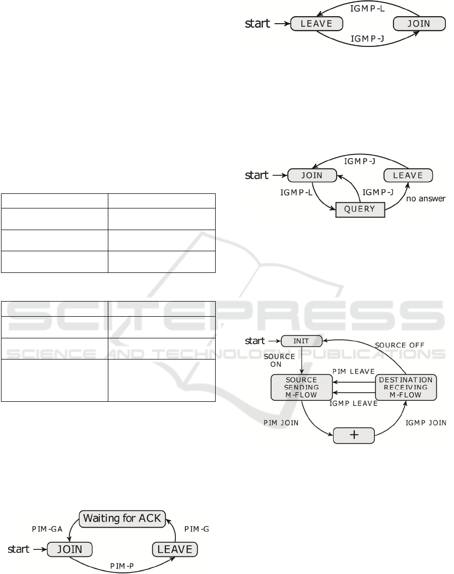
The state space for PIM-DM is shown in Figure
1, being JOIN the initial state of all PIM interfaces.
Figure 1: PIM-DM space state on multicast interfaces.
The state space for IGMP running on end hosts is
shown in Figure 2, being LEAVE the initial state.
Figure 2: IGMP space state in multicast end hosts.
On the other hand, IGMP on router interfaces
gets enabled at the same time as PIM is on those
particular interfaces. But its behaviour related to its
directly connected hosts leads to the following state
space for IGMP shown in Figure 3, being JOIN the
initial state.
Figure 3: IGMP space state in directly connected router
interfaces.
Eventually, when multicast Control traffic is
ready, hence both PIM and IGMP, multicast Data
traffic will be able to go all the way from a source to
every destination asking for receiving the multicast
flow, as stated in Figure 4, being INIT the initial
state.
Figure 4: Multicast flow space state for data streaming.
Each device involved in a multicast deploy will
have some determined features which will be
expressed by means of ACP syntax and semantics,
allowing the specification and verification of the
whole multicast environment.
According to ACP, each device will be modelled
as a process, as well as each link between such
devices. A single process might contain some
process terms, those being interrelated by different
compositions such as alternative ones, expressed by
additions, sequential ones, expressed by
multiplications, and concurrent ones, expressed by
merges, as well as linear recursion in order to
DCNET 2017 - 8th International Conference on Data Communication Networking
60
capture infinite behaviour and conditional operators,
such that:
FALSEconditionTRUE || .
After that, the internal actions of that model,
those being send
)(
, yx
s and read )(
, yx
r , where
x
is the transmitting end and
y
is the receiving end,
are forced into communication by means of an
encapsulation operator. Eventually, the remaining
internal communication actions might be made
invisible by using an abstraction operator, hence
leaving just the input and the output of such a model,
considering the whole internal system as black box.
If the outcome of such operations might be
equated by using the set of ACP axioms to the
process terms representing the desired external
behaviour of a particular real scenario, then this
proves the bisimilarity between the real scenario and
the ACP modelling, therefore they will both be
behaviourally equivalent.
It is to be noted that the concurrent operators
within a single process term may be composed by a
number of items. However, in order to simplify
calculations, they may be rewritten as a combination
of left merges and communication merges, no matter
how many of those items are run in a concurrent
fashion (Bergstra and Klop, 1984).
Regarding the outcome of communication
merges, if the send and receive actions share the
same departing and arriving points, then it will mean
communication takes place between those points,
but communication will yield deadlock if those
premises are not met.
At this point, a network topology will be
exhibited in order to study the packets involved in
the most common actions regarding multicast
streaming for Dense Mode.
Regarding the devices shown in the exhibits
hereinafter,
Vn represents video servers
transmitting through different multicast groups,
Hn
stands for host receivers and Rn defines routers,
where
n states the cardinal number referred to that
device. Apart from that, links among routers are also
shown as
Pmn , being m and n the cardinal
number of the routers involved in that path, as well
as links between hosts and their edge routers,
expressing switches interconnecting them as
SWn .
As a note aside, it is worth noting that respecting
routers, PIM-G must only be sent through RPF
interfaces, whereas with regard to switches, IGMP
snooping is considered on by default to prevent
receiving unwanted multicast traffic on a LAN.
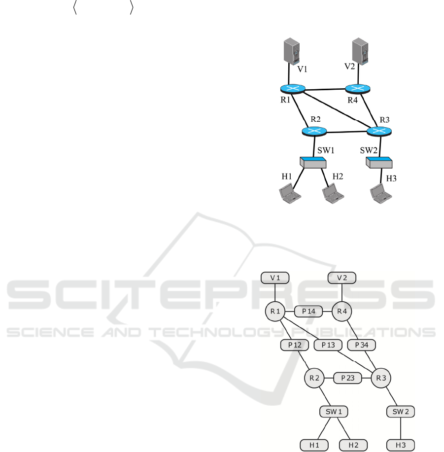
4.2 Network Topology and Modelling
First of all, let us consider a general network
topology such as the one exhibited in Figure 5.
Figure 5: Network topology used to study PIM-DM.
That topology may be broken down into its
forming devices and the links among them in order
to model each of them, as stated in Figure 6.
Figure 6: Model used to study PIM-DM.
Therefore, taking into account the topology
exposed in Figure 5, being modelled as in Figure 6,
we are going to define the process terms regarding
the objects taking part in it, noting where the
multicast flows are coming from and the RPF
interfaces on each router. As per the latter, it states
where the flow comes from, so where it may go to.
For clarification purposes, V1 flow reaches R1,
then, it is sent over to R2, R3 and R4, and after that
H1 and H2 are reached through R2 and H3 is fed
through R3. This may be seen in Figure 7.
Multicast Algebraic Formal Modelling using ACP - Study on PIM Dense Mode and Sparse Mode
61
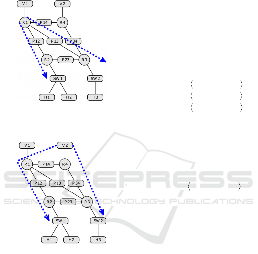
Figure 7: Model used to study V1 flow (SPT).
On the contrary, V2 flow reaches R4, then it is
sent over R3 to reach H3, whereas it is also
forwarded to R2 through R1 to reach H1 and H2.
Figure 8: Model used to study V2 flow (SPT).
In order to distinguish each multicast tree
sourced in each video server (SPT), subindexes will
be used in each PIM, IGMP and multicast stream
packet. Furthermore, linear recursion, which must be
expressed as
XaX ⋅= , has not been stated for
simplification purposes.
Therefore, the modelling designed for the present
network topology is going to be presented below.
= )(
11,11
mFLOWsV
RV
= )(
24,22
mFLOWsV
RV
()
()
()
()
|)(|)(
)(
))((
))(())((
))((
))(())((
))((
|)(|)(
|)(|)(
|)(|)(
)(
))(())((
))((
))(())((
))((
))(())((
))((
212212,1
21,14
21,13
21,14214,1
214,1
212,121,12
21,12
114114,1
113113,1
112112,1
11,1
114,111,14
11,14
113,111,13
11,13
112,111,12
11,121
JOINstatemFLOWs
mFLOWr
PPIMr
GAPIMrGPIMs
PPIMs
GAPIMsGPIMr
PPIMr
JOINstatemFLOWs
JOINstatemFLOWs
JOINstatemFLOWs
mFLOWr
GAPIMsGPIMr
PPIMr
GAPIMsGPIMr
PPIMr
GAPIMsGPIMr
PPIMrR
PPR
RP
RP
RPPR
PR
PRRP
RP
PPR
PPR
PPR
RV
PRRP
RP
PRRP
RP
PRRP
RP
⋅
⋅+
++
+⋅+
++
+⋅+
++
+
+
+
⋅
⋅+
+⋅+
++
+⋅+
++
+⋅+
+=
)()(
)(
))(())((
))(())((
)(
))(())((
)()(
)(
))(())((
))(())((
)(
))(())((
22,12212,1
212
22,12212,1
21,12212,2
212
21,12212,2
22,12212,1
112
12,12112,1
11,12112,2
112
11,12112,212
mFLOWsmFLOWr
JOINstate
GAPIMsGAPIMr
GPIMsGPIMr
LEAVEstate
PPIMsPPIMr
mFLOWsmFLOWr
JOINstate
GAPIMsGAPIMr
GPIMsGPIMr
LEAVEstate
PPIMsPPIMrP
RPPR
P
RPPR
RPPR
P
RPPR
RPPR
P
RPPR
RPPR
P
RPPR
⋅+
+⋅
⋅⋅⋅
⋅⋅+
+⋅
⋅⋅+
+⋅+
+⋅
⋅⋅⋅
⋅⋅+
+⋅
⋅⋅=
DCNET 2017 - 8th International Conference on Data Communication Networking
62

()
()
|)(|)(
)(
))(())((
))((
))((
))(())((
))((
|)(|)(
)(
))(())((
))((
))((
))(())((
))((
2121,2
22,12
21,222,1
22,1
22,23
22,12212,2
212,2
1111,2
12,12
11,212,1
12,1
123,2
12,12112,2
112,22
JOINstatemFLOWs
mFLOWr
QIGMPsLIGMPr
JIGMPr
PPIMr
GAPIMrGPIMs
PPIMs
JOINstatemFLOWs
mFLOWr
QIGMPsLIGMPr
JIGMPr
PPIMs
GAPIMrGPIMs
PPIMsR
SWSWR
RP
SWRRSW
RSW
RP
RPPR
PR
SWSWR
RP
SWRRSW
RSW
PR
RPPR
PR
⋅
⋅+
+⋅+
++
++
+⋅+
++
+⋅
⋅+
+⋅+
++
++
+⋅+
+=
()
()
()
+⋅⋅
⋅+
+⋅⋅
⋅+
+⋅
⋅+
+⋅
⋅⋅
⋅+
+⋅+
+⋅+
+⋅⋅
⋅+
+⋅⋅
⋅=
)())((
))((
)())((
))((
|)(|)(
)(
)(|)(|
))((
))((
))(())((
))(())((
)())((
))((
)())((
))((1
2122,1
21,2
2122,1
21,1
11,1
11,2
111
1,1
11,2
12,111,2
12,111,1
1112,1
11,2
1112,1
11,1
JOINstateJIGMPs
JIGMPr
JOINstateJIGMPs
JIGMPr
JOINstatemFLOWs
mFLOWr
LEAVEstateJIGMP
QIGMPs
QIGMPr
LIGMPsLIGMPr
LIGMPsLIGMPr
JOINstateJIGMPs
JIGMPr
JOINstateJIGMPs
JIGMPrSW
SWRSW
SWH
SWRSW
SWH
i
HiHiSW
SWR
SW
i
HiSW
SWR
RSWSWH
RSWSWH
SWRSW
SWH
SWRSW
SWH
()
()
()
⋅
⋅+
+⋅
⋅⋅
⋅+
+⋅+
+⋅+
i
HiHiSW
SWR
SW
i
HiSW
SWR
RSWSWH
RSWSWH
JOINstatemFLOWs
mFLOWr
LEAVEstateJIGMP
QIGMPs
QIGMPr
LIGMPsLIGMPr
LIGMPsLIGMPr
|)(|)(
)(
)(|)(|
))((
))((
))(())((
))(())((
22,1
21,2
212
2,1
21,2
22,121,2
22,121,1
()
()
|)(|)(
|)(|))((
))((
)())((
)())((
|)(|)(
|)(|))((
))((
)())((
)())((1
2121,1
2121,1
21,1
2121,1
2121,1
1111,1
1111,1
11,1
1111,1
1111,1
JOINstatemFLOWr
JOINstateJIGMPs
QIGMPr
LEAVEstateLIGMPs
JOINstateJIGMPs
JOINstatemFLOWr
JOINstateJIGMPs
QIGMPr
LEAVEstateLIGMPs
JOINstateJIGMPsH
HHSW
HSWH
HSW
HSWH
HSWH
HHSW
HSWH
HSW
HSWH
HSWH
⋅+
+⋅
⋅+
+⋅+
+⋅+
++
+⋅
⋅+
+⋅+
+⋅=
()
()
|)(|)(
|)(|))((
))((
)())((
)())((
|)(|)(
|)(|))((
))((
)())((
)())((2
2222,1
2222,1
22,1
2221,2
2221,2
1212,1
1211,2
12,1
1211,2
1211,2
JOINstatemFLOWr
JOINstateJIGMPs
QIGMPr
LEAVEstateLIGMPs
JOINstateJIGMPs
JOINstatemFLOWr
JOINstateJIGMPs
QIGMPr
LEAVEstateLIGMPs
JOINstateJIGMPsH
HHSW
HSWH
HSW
HSWH
HSWH
HHSW
HSWH
HSW
HSWH
HSWH
⋅+
+⋅
⋅+
+⋅+
+⋅+
++
+⋅
⋅+
+⋅+
+⋅=
Multicast Algebraic Formal Modelling using ACP - Study on PIM Dense Mode and Sparse Mode
63

)(
))(())((
)(
))(())((
223
22,23223,3
123
13,23123,223
LEAVEstate
PPIMsPPIMr
LEAVEstate
PPIMsPPIMrP
P
RPPR
P
RPPR
⋅
⋅⋅+
+⋅
⋅⋅=
)(
))(())((
)()(
)(
))(())((
))(())((
)(
))(())((
213
21,13213,3
13,13113,1
113
13,13113,1
11,13113,3
113
11,13113,313
LEAVEstate
PPIMsPPIMr
mFLOWsmFLOWr
JOINstate
GAPIMsGAPIMr
GPIMsGPIMr
LEAVEstate
PPIMsPPIMrP
P
RPPR
RPPR
P
RPPR
RPPR
P
RPPR
⋅
⋅⋅+
+⋅+
+⋅
⋅⋅⋅
⋅⋅+
+⋅
⋅⋅=
)()(
)(
))(())((
))(())((
)(
))(())((
)()(
)(
))(())((
))(())((
)(
))(())((
21,14214,4
214
21,14214,4
24,14214,1
214
24,14214,1
14,14114,1
114
14,14114,1
11,14114,4
114
11,14114,414
mFLOWsmFLOWr
JOINstate
GAPIMsGAPIMr
GPIMsGPIMr
LEAVEstate
PPIMsPPIMr
mFLOWsmFLOWr
JOINstate
GAPIMsGAPIMr
GPIMsGPIMr
LEAVEstate
PPIMsPPIMrP
RPPR
P
RPPR
RPPR
P
RPPR
RPPR
P
RPPR
RPPR
P
RPPR
⋅+
+⋅
⋅⋅⋅
⋅⋅+
+⋅
⋅⋅+
+⋅+
+⋅
⋅⋅⋅
⋅⋅+
+⋅
⋅⋅=
+⋅
⋅⋅+
+⋅
⋅⋅=
)(
))(())((
)(
))(())((
234
24,34234,3
134
14,34134,334
LEAVEstate
PPIMsPPIMr
LEAVEstate
PPIMsPPIMrP
P
RPPR
P
RPPR
)()(
)(
))(())((
))(())((
23,34234,4
234
23,34234,4
24,34234,3
mFLOWsmFLOWr
JOINstate
GAPIMsGAPIMr
GPIMsGPIMr
RPPR
P
RPPR
RPPR
⋅+
+⋅
⋅⋅⋅
⋅⋅+
()
()
+
⋅
⋅+
+⋅+
++
+⋅+
++
++
+⋅+
+=
|)(|)(
|)(|)(
)(
))(())((
))((
))(())((
))((
))((
))(())((
))((
234234,4
214214,4
24,2
214,424,34
24,34
214,424,14
24,14
14,34
14,14114,4
114,44
JOINstatemFLOWs
JOINstatemFLOWs
mFLOWr
GAPIMsGPIMr
PPIMr
GAPIMsGPIMr
PPIMr
PPIMr
GAPIMrGPIMs
PPIMsR
PPR
PPR
RV
PRRP
RP
PRRP
RP
RP
RPPR
PR
()
()
|)(|)(
)(
))(())((
))((
))((
))((
))(())((
))((
|)(|)(
)(
))(())((
))((
))((
))((
))(())((
))((
2121,2
22,12
21,222,1
22,1
223,3
213,3
23,34234,3
234,3
1212,3
13,13
12,313,2
13,2
134,3
123,3
13,13113,3
113,33
JOINstatemFLOWs
mFLOWr
QIGMPsLIGMPr
JIGMPr
PPIMs
PPIMs
GAPIMrGPIMs
PPIMs
JOINstatemFLOWs
mFLOWr
QIGMPsLIGMPr
JIGMPr
PPIMs
PPIMr
GAPIMrGPIMs
PPIMsR
SWSWR
RP
SWRRSW
RSW
PR
PR
RPPR
PR
SWSWR
RP
SWRRSW
RSW
PR
PR
RPPR
PR
⋅
⋅+
+⋅+
++
++
++
+⋅+
++
+⋅
⋅+
+⋅+
++
++
++
+⋅+
+=
DCNET 2017 - 8th International Conference on Data Communication Networking
64
()
()
|)(|)(
)(
)(|)(|
))(())((
))(())((
)())((
))((
|)(|)(
)(
)(|)(|
))(())((
))(())((
)())((
))((2
2323,2
22,3
222
23,221,2
23,222,3
2223,2
22,3
1313,2
12,3
121
1,212,3
13,212,3
1213,2
12,3
JOINstatemFLOWs
mFLOWr
LEAVEstateJIGMP
QIGMPsQIGMPr
LIGMPsLIGMPr
JOINstateJIGMPs
JIGMPr
JOINstatemFLOWs
mFLOWr
LEAVEstateJIGMP
QIGMPsQIGMPr
LIGMPsLIGMPr
JOINstateJIGMPs
JIGMPrSW
HHSW
SWR
SW
HSWSWR
RSWSWH
SWRSW
SWH
HHSW
SWR
SW
HiSWSWR
RSWSWH
SWRSW
SWH
⋅
⋅+
+⋅
⋅⋅+
+⋅+
+⋅⋅
⋅+
+⋅
⋅+
+⋅
⋅⋅+
+⋅+
+⋅⋅
⋅=
()
()
()
|)(|)(
|)(|))((
))((
)())((
)())((
|)(|)(
|)(|))((
))((
)())((
)())((3
2323,2
2322,3
23,2
2322,3
2322,3
1313,2
1312,3
13,2
1312,3
1313,2
JOINstatemFLOWr
JOINstateJIGMPs
QIGMPr
LEAVEstateLIGMPs
JOINstateJIGMPs
JOINstatemFLOWr
JOINstateJIGMPs
QIGMPr
LEAVEstateLIGMPs
JOINstateJIGMPsH
HHSW
HSWH
HSW
HSWH
HSWH
HHSW
HSWH
HSW
HSWH
HSWH
⋅+
+⋅
⋅+
+⋅+
+⋅+
++
+⋅
⋅+
+⋅+
+⋅=
5 BASIC MODEL FOR PIM-SM
Analogously as the previous Section, a simplified
version of PIM Sparse Mode and IGMP protocols is
going to be implemented in order to get a basic
model for multicast streaming running in Sparse
Mode, meeting the asynchronous specifications
given in Section 2, thus not taking into account
timing considerations.
5.1 Introduction
The packet types being used for PIM-SM protocol
are shown in Table 3, whereas IGMP protocol
dynamics are the same as described in the previous
Section, as well as the rest of considerations exposed
therein.
Table 3: PIM-SM actions for Basic modelling.
PIM Packet Type Meaning
PIM-J
Router joins the
multicast flow
PIM-P
Router prunes the
multicast flow
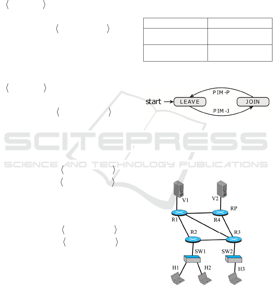
The state space for PIM-SM is seen in Figure 9,
being LEAVE (Prune) the initial state of PIM links.
Figure 9: PIM-SM space state on multicast interfaces.
5.2 Network Topology and Modelling
The network topology to be considered herein is the
same as the one presented in Section 4, with the only
difference being that now R4 has been appointed as
the RP.
Figure 10: Network topology used to study PIM-SM.
Analogously as in the former Section, this
topology may be modelled as stated in Figure 11,
considering that RP is the middle point for all flows.
Multicast Algebraic Formal Modelling using ACP - Study on PIM Dense Mode and Sparse Mode
65
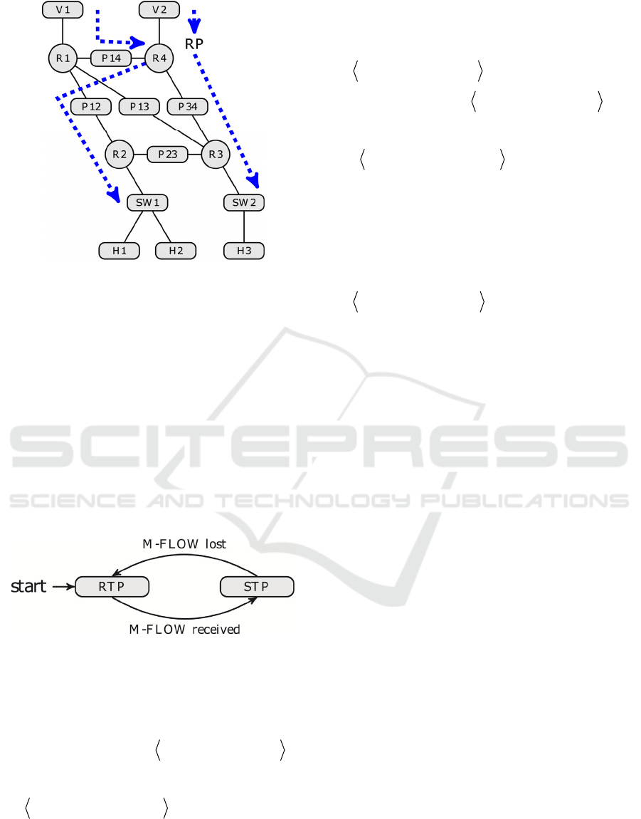
Figure 11: Model used to study V1 and V2 flows (RPT).
Therefore, the modelling designed for this
network topology is the same for multicast sources
as it is for PIM-DM, as they just send the flow to
their source DR, and also for multicast destinations
and their switches, as they just work with IGMP.
On the contrary, routers and links among them
differ from the previous case in two main points.
First, they deal with PIM packets following the RPT
instead of SPT. Second, the multicast flows follow
RTP until those flows reach each client DR, and at
that moment RPT swaps to SPT if the path from a
particular client to the desired source is shorter, so
an extra state must be added up to every client DR
for each flow, as shown in Figure 12.
Figure 12: Types of tree on multicast Sparse Mode.
So, here it is the modelling for the new items,
those being the four routers and all the links among
them, as the rest of the items remain the same.
()
+⋅+
++
+
⋅
+
+=
))(())((
))((
|)(|
)())((
|)(|))((
11,212,1
12,1
11
12112,2
11112,22
QIGMPsLIGMPr
JIGMPr
LEAVEstate
RPTstatePPIMs
JOINstateJPIMsR
SWRRSW
RSW
SW
RPR
SWPR
()
⋅
⋅
⋅+
+⋅+
++
+
⋅
+
++
+
⋅
⋅
⋅+
|)(|
)()(
)(
))(())((
))((
|)(|
)())((
|)(|))((
|)(|
)()(
)(
21
2221,2
22,12
21,222,1
22,1
21
22212,2
21212,2
11
1211,2
12,12
JOINstate
SPTstatemFLOWs
mFLOWr
QIGMPsLIGMPr
JIGMPr
LEAVEstate
RPTstatePPIMs
JOINstateJPIMs
JOINstate
SPTstatemFLOWs
mFLOWr
SW
RSWR
RP
SWRRSW
RSW
SW
RPR
SWPR
SW
RSWR
RP
)()(
)(
))(())((
)(
))(())((
)()(
)(
))(())((
)(
))(())((
22,12212,1
212
21,12212,2
212
21,12212,2
22,12212,1
112
11,12112,2
112
11,12112,212
mFLOWsmFLOWr
LEAVEstate
PPIMsPPIMr
LEAVEstate
JPIMsJPIMr
mFLOWsmFLOWr
LEAVEstate
PPIMsPPIMr
JOINstate
JPIMsJPIMrP
RPPR
P
RPPR
P
RPPR
RPPR
P
RPPR
P
RPPR
⋅+
+⋅
⋅⋅+
+⋅
⋅⋅+
+⋅+
+⋅
⋅⋅+
+⋅
⋅⋅=
)()(
)(
))(())((
)(
))(()((
13,13113,1
113
11,13113,3
113
11,13113,313
mFLOWsmFLOWr
LEAVEstate
PPIMsPPIMr
JOINstate
JPIMsJPIMrP
RPPR
P
RPPR
P
RPPR
⋅+
+⋅
⋅⋅+
+⋅
⋅⋅=
NotApplyP
23
DCNET 2017 - 8th International Conference on Data Communication Networking
66

()
|)(|)(
)(
))(())((
)(())((
|)(|
|)(|
)(
)(
)(
|)(|
|)(|
)(
|)(|
|)(|
)(
)(
)(
|)(|
|)(|
)(
)(
))(())((
))(())((
212212,1
21,14
214,121,12
214,121,12
13
114
113,1
11,14
114,1
13
113
113,1
12
112
112,1
11,14
114,1
12
112
112,1
11,1
114,111,12
114,111,121
JOINstatemFLOWs
mFLOWr
PPIMsPPIMr
JPIMsJPIMr
RPTstateAND
JOINstate
mFLOWs
mFLOWr
mFLOWs
SPTstateAND
JOINstate
mFLOWs
RPTstateAND
JOINstate
mFLOWs
mFLOWr
mFLOWs
SPTstateAND
JOINstate
mFLOWs
mFLOWr
PPIMsPPIMr
JPIMsJPIMrR
PPR
RP
PRRP
PRRP
R
P
PR
RP
PR
R
P
PR
R
P
PR
RP
PR
R
P
PR
RV
PRRP
PRRP
⋅
⋅+
+⋅+
+⋅+
+
⋅
⋅⋅
⋅
+
+
+
+
⋅
⋅⋅
⋅
+
+
⋅
⋅+
+⋅+
+⋅=
+⋅⋅
⋅⋅+
+⋅
⋅⋅+
+⋅
⋅⋅=
)()(
)()(
)(
))(())((
)(
))(())((
11,14114,4
14,14114,1
114
14,14114,1
114
14,14114,114
mFLOWsmFLOWr
mFLOWsmFLOWr
LEAVEstate
PPIMsPPIMr
JOINstate
JPIMsJPIMrP
RPPR
RPPR
P
RPPR
P
RPPR
)()(
)(
))(())((
)(
))(())((
21,14214,4
214
24,14214,1
214
24,14214,1
mFLOWsmFLOWr
LEAVEstate
PPIMsPPIMr
JOINstate
JPIMsJPIMr
RPPR
P
RPPR
P
RPPR
⋅+
+⋅
⋅⋅+
+
⋅⋅+
+
+
⋅
⋅+
+++
+++
+
+
+
⋅
⋅+
+++
++=
|)(|
)(
|)(|
)(
)(
))(())((
))(())((
|)(|
)(
|)(|
)(
)(
))(())((
))(())((
234
234,4
214
214,4
24,2
24,3424,34
24,1424,14
134
134,4
114
114,4
14,14
14,3414,34
14,1414,144
JOINstate
mFLOWs
JOINstate
mFLOWs
mFLOWr
PPIMrJPIMr
PPIMrJPIMr
JOINstate
mFLOWs
JOINstate
mFLOWs
mFLOWr
PPIMrJPIMr
PPIMrJPIMrR
P
PR
P
PR
RV
RPRP
RPRP
P
PR
P
PR
RP
RPRP
RPRP
)()(
)(
))(())((
)(
))(())((
)()(
)(
))(())((
)(
))(())((
23,34234,4
234
24,34234,3
234
24,34234,3
13,34134,4
134
14,34134,3
134
14,34134,334
mFLOWsmFLOWr
LEAVEstate
PPIMsPPIMr
JOINstate
JPIMsJPIMr
mFLOWsmFLOWr
LEAVEstate
PPIMsPPIMr
JOINstate
JPIMsJPIMrP
RPPR
P
RPPR
P
RPPR
RPPR
P
RPPR
P
RPPR
⋅+
+⋅
⋅⋅+
+⋅
⋅⋅+
+⋅+
+⋅
⋅⋅+
+⋅
⋅⋅=
Multicast Algebraic Formal Modelling using ACP - Study on PIM Dense Mode and Sparse Mode
67

()
()
()
⋅
⋅
⋅+
+⋅+
++
+
⋅
+
++
+⋅
⋅+
+
⋅
⋅
⋅+
+⋅+
++
+
⋅
+
+=
|)(|
)()(
)(
))(())((
))((
|)(|
)())((
|)(|))((
|
)(|)(
)(
|)(|
)()(
)(
))(())((
))((
|)(|
)())((
|)(|))((
22
2322,3
23,34
22,323,2
23,2
22
23234,3
22234,3
1212,3
13,13
12
1312,3
13,34
12,313,2
13,2
12
13134,3
12134,33
JOINstate
STPstatemFLOWs
mFLOWr
QIGMPsLIGMPr
JIGMPr
LEAVEstate
RPTstatePPIMs
JOINstateJPIMs
JOINstatemFLOWs
mFLOWr
JOINstate
SPTstatemFLOWs
mFLOWr
QIGMPsLIGMPr
JIGMPr
LEAVEstate
RPTstatePPIMs
JOINstateJPIMsR
SW
RSWR
RP
SWRRSW
RSW
SW
RPR
SWPR
SWSWR
RP
SW
RSWR
RP
SWRRSW
RSW
SW
RPR
SWPR
6 CONCLUSIONS
In this paper, two multicast transmission models
have been presented using ACP syntax and
semantics, taking PIM specifications as a base. Each
of those models has been created using the same
network topology, so as to appreciate the similarities
and differences between them both.
The first one is PIM Dense Mode, where
multicast stream flows all over the network by
default, whilst the second one is PIM Sparse Mode,
where there is just the opposite condition.
Both models cover the joining and leaving
mechanism for any of the clients proposed, as well
as the proper behaviour of the network devices,
which leads to receive or quit the multicast flow as
expected.
Further modelling might be performed by also
taking into account the synchronous messages
within the PIM specifications, such as sending and
receiving PIM Hello packets among all neighbours
running PIM every 30 seconds so as to check
whether the proper interfaces are still within the PIM
domain, with a timeout of 105 seconds.
This is to be applied to both PIM modes, but also
there are some further timing features that might be
applied for a particular mode, such as applying a
timeout for the PIM-GA message of 3 seconds in
PIM-DM, or otherwise the process of waiting for 60
seconds when an RP receives a flow from a source
and there are no clients asking for it in PIM-SM.
All those features would make both models
closer to the real behaviour of PIM, although the
basics of multicast operations may remain the same
as stated in the present paper.
REFERENCES
RFC 3973, 2005, Protocol Independent Multicast – Dense
Mode (PIM-DM): Protocol Specification (Revised),
IETF.
RFC 7761, 2016, Protocol Independent Multicast – Sparse
Mode (PIM-SM): Protocol Specification (Revised),
IETF.
RFC 2236, 1997, Internet Group Management Protocol,
Version 2, IETF.
Turner, K. J., 1993, Using Formal Description
Techniques: An Introduction to Estelle, Lotos and
SDL, John Wiley and Sons, 1
st
edition.
Padua, D. A., 2011, Encyclopedia of Parallel Computing,
Springer, 1
st
edition.
Bergstra, J. A., Klop, J. W., 1985, Algebra of
communicating processes with abstraction,
Theoretical Computer Science, Vol. 35, pages 77-121.
Fokkink, W., 2007, Introduction to Process Algebra,
Springer-Verlag, 2
nd
edition.
Fokkink, W., 2016, Modelling Distributed Systems,
Springer, 2
nd
edition.
Groote, J. F., Mousavi, M. R., 2014, Modelling and
Analysis of Communicating Systems, MIT Press, 1
st
edition.
Lockefeer, L., Williams, D. M., Fokkink, W., 2016,
Formal specification and verification of TCP extended
with the Window Scale Option, Science of Computer
Programming, Vol. 118, pages 3-23.
Bergstra, J. A., Klop, J. W., 1984, Verification of an
Alternating Bit Protocol by Means of Process Algebra,
Lecture Notes in Computer Science, Vol. 215, pages
9-23.
DCNET 2017 - 8th International Conference on Data Communication Networking
68
