
Checking Realizability of a Timed Business Processes Choreography
Manuel I. Capel
Software Engineering Department, Granada University,
Periodista Daniel Saucedo Aranda, 18071 Granada, Spain
Keywords:
Business Process Management, Business Process as a Service, BPMN, Process Modeling, Temporal Con-
straints and Dependencies, Temporal Semantics.
Abstract:
A business process (BP) can be understood as a set of related, structured, interacting services acting as peers,
according to an intended choreography that is capable of giving complex functionality to customers. Several
authors have made progress in solving the ”choreography realization” problem. The research work carried out
in this paper amounts to analyzing and automatically checking the realizability of the defined choreography
for services that communicate through messages in a general, distributed, and highly parallel system.
1 INTRODUCTION
Busines Process Model and Notation (BPMN) was
extended into BPMN 2.0 to provide an interaction
model for the business processes (BP) which is based
on specification of choreographies as opposed to “in-
terconnected interface models” (Poizat P., 2012) that
promote orchestration-oriented specifications, which
is a bottom-up and a local approach of service com-
position.
Realizability of choreographies consists of to for-
mally determine if the individual peers obtained from
a choreography, independently from the kind of com-
munication or their relative execution order, are capa-
ble of interacting as prescribed in the choreography
requirement specification. We can say that a chore-
ography is realizable if all the interactions specified
in BPMN 2.0 choreography-diagrams are equivalent
to those that can be executed by the interacting peers
when the BP model is implemented in a Web-services
description language. In this way, a formalization of
behavioral and temporal aspects of BPMN 2.0 mod-
els through a provably-realizable choreography will
provide important benefits at analysis and design of
complex applications built over distributed and highly
parallel platforms.
There are already contributions to the resolution
of the choreography realization problem (Rozinat A.,
2006), (Dongen B., 2004). The research work up until
now can be divided into two categories. The first ap-
proach aims at transforming BPMN models into ex-
ecutable environments (Capel M.I., 2014) and per-
forming formal analysis (Aalst, 2009). The second
one includes formal methods for BPMN models veri-
fication, which are based on Π-calculus (Milner, Hall)
or Petri Nets (Cerone, 2002), which can debug gram-
matical errors and can transform business processes
diagrams (BPD) into BP Execution Language (BPEL)
code (Arkin A., 2005; OASIS, 2007), or representing
BPM system properties with CCTL. In this second
group, the central problem to tackle consists of prov-
ing the soundness of BPMN model transformation.
BPMN transformation is more than just individu-
ally converting the model’s entities. In many cases, a
model cannot be verified because its representation in
an executable environment does not react to external
events in the same way.
We propose here a solution to that problem based
on the transformation of the BPMN and the peer-
system models into a formal specification, realized in
the timed process calculus named CSP+T, thereby al-
lowing their complete verification with state-of-the-
art model checking tools.
In Section 2 we introduce the use of BPMN 2.0
for choreography specification. Section 3 presents
our formal model transformation from BPMN 2.0
choreographies into CSP+T process calculus. Sec-
tion 4 shows how this encoding can be used to reify
choreographies with LTS, and check their realizabil-
ity. Model checking of choreographies is addressed in
Section 5, and tool support is discussed in section 6.
Finally, the conclusions and future leads of our work.
Capel, M.
Checking Realizability of a Timed Business Processes Choreography.
DOI: 10.5220/0006300404410448
In Proceedings of the 7th International Conference on Cloud Computing and Services Science (CLOSER 2017), pages 413-420
ISBN: 978-989-758-243-1
Copyright © 2017 by SCITEPRESS – Science and Technology Publications, Lda. All rights reserved
413
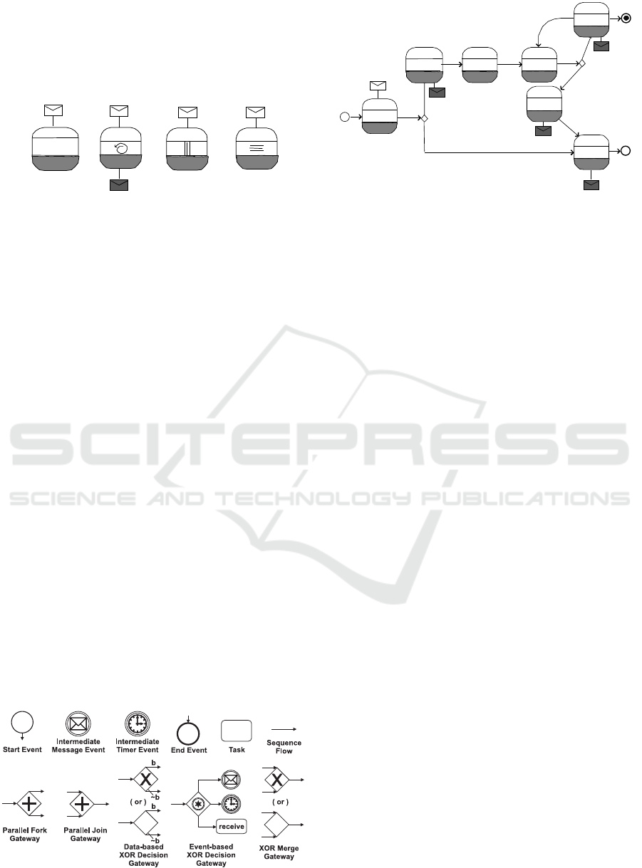
Figure 1: Graphical representation of BPMN elements.
2 BPMN CHOREOGRAPHIES
FORMALIZATION
The graphical standardized notation Business Pro-
cess Model and Notation (BPMN) (OMG, 2011) pro-
vides representation elements for business processes
with an emphasis on control–flow. BPMN intro-
duces a specific type of flowchart, named Business
Process Diagram (BPD), which provides graphical
constructs tailored to model BPMN elements, such
as: (a)gateways, (b) events start, stop, (c)tasks, and
(d)control flows. Non-technical personnel, usually
management-oriented, can easily understand a BPD
diagram and use it for modeling BPs. The appar-
ent simplicity of BPD, however, offers the neces-
sary expressiveness power to model very complex
BPs and it can be mapped to different business exe-
cution languages such as BPEL (Arkin A., 2005) or
XLANG (Thatte, 2001). Figure 1 shows BPMN ele-
ments as they are represented in BPD.
Semi-formal specification of task workflows can
be done with BPMN notation.
BPMN 2.0 supports the collaboration between
analysis entities in BP models, which brings forward
a choreographic model based on peer interactions, in-
stead of following a design model based on services
orchestration. Thus, it promotes a collaborative and
abstract description of software systems that allows
for focusing more on what services do in a compo-
sition than on how they do it. Interactions between
system’s components or peers should be more pre-
cisely described now than in “interconnected inter-
face” models, within which the interactions are de-
fined internally to each peer only. Contrary to inter-
face description–based, “interaction–based” models
consider the description of “conversations” between
peers as the basic building blocks of any BP system
design, whereas the specification of interfaces then
alt
LifeLine
Pharmaceutical
warehouse
Pharmacy
Ward
8: Prepare
drug
9: Prepare
drug
7: Delivered
6: Delivered
5: Found
4: Purchase
order
3: Prepare
order
2: Send internal
order
1: Search drug
Visual Paradigm Standard Edition(Universidad Granada)
Figure 2: Ward-Pharmacy interaction as a UML sequence
diagram.
becomes secondary to the system’s properties anal-
ysis.
Case Study. We will use a Pharmacy Hospital
logistic process as a simple running example. The
UML sequence-diagram in Figure 2 depicts the mes-
sage flows between two participants, the Ward and the
Pharmacy, which are independent BP and may have
been constructed separately. Clearly, the synchtron-
ization between both participants is a necessary be-
havioural property for successful collaboration. The
Ward-Pharmacy interaction choreography is realiz-
able if that property is individually proved for each
participant.
2.1 Coreography Description Language
BPMN 2.0 has introduced the Choreography Descrip-
tion Language (CDL) for specifying the requirements
of a business process choreography. CDL is capable
of defining, from an integrated point of view, the com-
mon and complementary observable behavior of dif-
ferent services that exchange messages according to
some ordered protocol for accomplishing a common
business goal (W3C, 2005).
Peers interactions are the basic building blocks of
any CDL specification. Peers A and B are repre-
sented by the upper and lower bands, respectively,
in the round boxes of Figure 3. One–way and two–
way interactions between peers are easily described
by BPMN 2.0 Choreography Diagrams (BCD).
CLOSER 2017 - 7th International Conference on Cloud Computing and Services Science
414
In a choreography, two-way interactions of peers
(tasks) are represented by message exchanging. A is
called the initiating peer and is represented by a white
band as opposite to the dark filled one for the the re-
ceiving peer B.
Choreogra-
phy-
task name
A A
A A
B
B
B
B
(a)
(b)
(c)
(d)
Figure 3: BPMN 2.0 choreography diagram tasks.
There are one-way interactions (Figure 3, a,c,d)
and two-way interactions (Figure 3, b). Two-way
interactions are represented by an intiating message
(white envelope) and a return message (black enve-
lope). Tasks can also include internal markers, such
as the standard loop (Figure 3, b), in which the in-
teraction is performed several times depending on a
boolean condition. In Multi–instance parallel loops
(Figure 3, c,d), the interactions are performed by sev-
eral instances of the choreography task, which can ex-
ecute the actions in parallelk | or sequentially ≡. If the
message exchange need not be repeated, no marker is
used to describe a task.
Business decisions and flow branching are mod-
elled using gateways, which are similar to decision
symbols in a flowchart. Gateways describe how se-
quence flows join (multiple outgoing sequence flows
and at most one incoming sequence flow), and fork
(multiple incoming sequence flows and at most one
outgoing sequence flow). In our description language
we take into account (Figure 4) the following sym-
bols for gateways: XOR exclusive gateways (deci-
sion, alternative paths), inclusive gateways (inclusive
decision, but also parallel paths), parallel gateways
(creating and merging parallel flows) and event-based
gateways (choices based on events). Diagrams need-
ing both converging and diverging choices can be de-
scribed by a sequence of single-converging/diverging
gateways.
Figure 4: BPMN Elements Extended Graphical Represen-
tation.
Demand
drug
Customer
Send internal
order
Ward
request
Pharmacy Pharmacy
Prepare
drug
Pharmacy
Pharmacy
Search
drug
Prepare
order
Deliver
drug
Purchase
order
received
purchase
order
placed
delivered
connect
Ward
Customer
Ward
DB
Ward
Ward
Pharmacy
Ward
Figure 5: BCD of the Ward-Pharmacy example.
BCD of the Case Study. From the pharmacy-
participant perspective, a deliver drug message is
sent to the ward-participant for guaranteeing that
a prior demanded drug is now available; and an
internal order received prior a purchase order for
a specific drug is made or sent. The ward-participant
has to send the demand drug message with enough
time in advance to guarantee one drug availability to
begin a medical treatment.
The specification in the BCD (Figure 5)
shows the interaction between the peers
(customer,ward,pharmacy,db) of the choreog-
raphy, translated from the business process model of
‘Logistic Process in Hospitals’ (Baacke L., 2009) that
represents the behaviour of tasks within the 2 pools
(BPMN notation to define task sequences): Ward
and Pharmacy of the example. In this specification,
we can firstly see that the customer interacts with
the ward (connect), then the ward sends the pre-
scription to the pharmacy (request) and eventually
receives the drug when it is available (received).
If that drug is not in stock, the pharmacy makes an
order (purchase order), communicates (purchase
order placed) to the ward and when the drug is
available, it delivers the drug to the ward. Finally,
the prescription will be prepared and given to the
customer (delivered), thereby terminating the
complete protocol.
WS-CDL Description. The Web Services
Choreography Description Language (WS-CDL) is
an XML-based language for describing Web services
interactions (W3C, 2005). In WS-CDL there is no
centralized control to coordinate different services;
and therefore, there are no global variables, condi-
tions or workunits either. In order to give the illusion
of a global or shared state among the choreographed
services, the variables located in one service can be
aligned (synchronized) via message passing with
other variables located in a distinct service. Message
Checking Realizability of a Timed Business Processes Choreography
415

sequences that do not follow the ordering rules
are considered out of sequence messages and the
language shows an error of conformance with respect
to the description of the intended choreography. The
lack of formal semantics of WS-CDL is currently
considered an issue since it hinders the development
of tool support for verifying message conformance
to a specific choreography description. In addition
to conformance checking, we need to determine
whether a given choreography is realizable, i.e.,
if its individual peers obtained through projection
from a choreography interact as prescribed in the
specification of choreography requirements.
3 ENCODING BPMN 2.0 INTO
CSP+T
CSP+T (Zic, 1994) is a real–time specification lan-
guage which extends Communicating Sequential Pro-
cesses (CSP) allowing the description of complex
event timings, within a single sequential process, for
use in the behavioural specification of any critical
communicating process. A CSP+T process term P is
defined as a tuple (αP,P), where αP = Comm act(P)∪
Interface(P) is the communication alphabet of P.
BPMN 2.0 into CSP. There have been sev-
eral proposals to formalize BPMN 2.0 non–temporal
constructs with process algebras, (Puhlmann, 2007;
Ma S., 2008; Mendoza L.E., 2012).
In the CCS–based notation proposed
in (Wong P.Y.H., 2008), which we will follow
in the sequel, each BPMN entity has associated
attributes describing its properties; for example the
number of loops of a sequence multiple instance is
recorded by the natural number in the constructor
miseq.
The formal semantics of BPMN abstracts (partial
function hide) the internal flow of the modeling entity
named state and only describes the sequence of ini-
tializations and terminations with the semantic func-
tion bpmn.
The type of a sequence flow or an exception flow
is given by the following schema definition:
Transition b= [guard : Guard; line : Line]
and the type of message flow:
Message flow b= [message : Message; channel : Channel]
If the sequence flow has no guard or the message
flow contains an empty message, then the values of
Transition and Message flow record the default val-
ues “tt” and empty respectively. There are five sets
of message flows (send, receive, reply, accept, break)
associated to the state entity, which are syntactically
defined in the next type and whose function follows
from their names,
State b= [type : Type; in, out, error : P Transition; exit :
P(N × Transition); send, receive,reply, accept, break :
P Message flow; link : P(Transition × Message flow);
depend :
P(Message flow × Message flow); loopMax : N]
Each state also incorporates the variable loopMax to
limit the number of state instances that each pro-
cess can invoke. The state’s component link pairs
the incoming message flow which initiates or inter-
rupts the execution of the state with either an incom-
ing transition or an exception flow. The component
depend pairs each incoming message that initializes
the state’s execution with its corresponding outgoing
message flow.
[bpmn]
bpmn : P Name 7→ Local 7→ Process
hide : P Name 7→ Local 7→ P Event
function name = (Y | [αY]X)\hide(| S |))
Where X = 2
i
: αY\hide(fin, abt) •
(i → X 2 fin → null 2 abt → stop)
And Y = (k
i
: Process set • α(P
i
) ◦ P(i))
The partial function bpmn maps a syntactic descrip-
tion of a BPMN diagram encapsulated by a pool
or BPMN–subprocess into a parallel composition of
CSP+T subprocesses, which correspond to the dia-
grams of the basic elements of BPMN shown in Fig-
ure 1. The set αY represents the communication al-
phabet that includes all the messages types and events
that may affect the execution of processes. These
communications represent the events that a process
P receives from its environment (made up of all the
other processes in the system) or those events that oc-
cur internally, i.e., which are not externally visible.
3.1 BPMN 2.0 Temporal Extension
In many models of choreographies, constraints on
time and resources appear that may cause the viola-
tion of the system’s safety properties.
In BPMN 2.0 the intermediate event (timer) ad-
mits the definition of a delay period, but the minimum
and maximum execution time allowed for any activity
cannot be specified as a task element.
We propose to extend BPMN 2.0, so that in-
cludes temporal attributes for specifying temporal
constraints for task and other modelling elements. An
intermediate event (timer) and a sub–process (time-
out) represent a temporal constraint on the task flow.
Notice that in BPMN 2.0 we can use the attribute of
the timer element to define the task delay period.
CLOSER 2017 - 7th International Conference on Cloud Computing and Services Science
416
Start Event. The schema labelled Start event
represents the necessary instantiation of an activity
prior to the start of its execution. To allow this in
CSP+T, the specification of this event is represented
by means of the F instantiation event according to
the following pattern,
P(start) =F 1 v
F
→ SKIP # (P(S1)2ε
end
→ SKIP)
Minimum and Maximum Duration Time of an
Activity. The invocation of activities that make up a
BP must be performed timely.
Let bpmn S1 be the activity that comes before ac-
tivity bpmn S2 (figure 6). Thus, it should be guar-
anteed that the execution time of bpmn S1 activ-
ity does not overrun its maximum range of duration
(S1.ran.max) and it does not occur before its mini-
mum starting time (S1.ran.min) elapses. If the above
times are not controlled, the activity fails and thus we
cannot certify the temporal properties of the business
process.
Figure 6: Temporal Annotations of the Activity.
Thus, the occurrence of ε
S2
must satisfy the condition,
v
S1
+ S1.ran.min ≤ s(ε
S2
) ≤ v
S1
+ S1.ran.max.
With CSP+T we are allowed to precisely specify the
time frame for the execution of an activity. The
CSP+T pattern corresponding to two consecutive ac-
tivities (S1 and S2) is as it follows,
P(S1)= ε
S1
1 v
S1
→ SKIP#
(I(Time, v
S1
+ S1.ran.min).ε
S2
→ SKIP #P(S2)
2ε
end
→ SKIP)
Time= S1.ran.max − S1.ran.min
The measured range values S
x
.ran.min and
S
x
.ran.max depend on event ε
Sx
occurrence.
Timed Exception Flow. BPMN proposes two
versions of type boundary event to represent timeouts.
Timer boundary represents the occurrence of an event
ε
exc
(see Figure 7) that either triggers a parallel thread
or interrupts the execution of activity bpmn S1 at
itime.ran time units after the inception of S
1
. Hence,
there are two instances of the modelling entity timer
boundary even, depending on whether the activity
started at ε
S1
is interrupted or not when this event
occurs. The itime.ran time period must be therefore
constrained by the maximum time limit that we have
associated to any activity.
(itime.ran < S1.ran.max) ∧ (s(ε
exc
) =
v
S1
+ itime.ran) ∧ (s(ε
exc
) ∈ [v
S1
, S1.ran.max))
Figure 7: Timed Exception Flow.
To specify the behavior denoted by a interrupting
timed exception flow, we use the interrupt operator
(4) in CSP+T, according to the following pattern,
P(S1) =(ε
S1
1 v
S1
→ SKIP#
(I(Time, v
S1
+ S1.ran.min).ε
S2
→
(SKIP #P(S2)
a
I(itime.ran, v
S1
) → SKIP #ε
exc
→
SKIP #P(S3))
2ε
end
→ SKIP))
Time = S1.ran.max − S1.ran.min
To represent a non–interrupting exception flow,
we only need to substitute the interrupt operator (4)
for the parallel operator k or the interleaving ||| of ac-
tivities in CSP+T.
4 CHOREOGRAPHY ANALYSIS
Any choreography can be considered realizable if all
the interactions that we have specified in the BPMN
2.0 diagram (e.g., the one in Figure 5) are equiva-
lent to those that can be executed by the interacting
peers when we implement the model in a service-
description language, such as WS-CDL.
Labelled transition system models
(LTS) (Bezem M., 2003) reify choreographies
and then allows the verifier to check its realizability
w.r.t. the model of the system composed of inter-
acting peers, which are also individually described
as LTS (Figure 8). The reification of the case study
choreography is shown in Figure 9.
4.1 Behavioral Equivalence
We encode both, the choreography and the interacting
peers, into bpmn process terms that are semantically
defined by the CSP+T (Zic, 1994) process calculus.
In this way, we can count on a sound and well defined
formalization of behavioral aspects of BPMN models
in order to allow the designer to carry out an analysis
of choregraphies.
Checking Realizability of a Timed Business Processes Choreography
417

The proposed analysis procedure for checking
choreography realizability consists of the following
integrated steps,
1. Generate the CSP+T encoding of a given chore-
ography.
2. The derived choreography reification (LTS) is
generated from the CSP+T description.
3. For the extracted interacting peers of the chore-
ografy, each peer is encoded as one CSP+T pro-
cess (using the bpmn pattern).
4. The distributed system model is built as a parallel
composition of the structured process terms.
5. The choreography reification is model–checked.
to prove behavioral equivalence with the peer-
based and distributed system model (in 4).
If the two models mentioned above are behaviorally
equivalent then the model-checker response is void,
meaning that the peer generation exactly satisfies the
BPMN communication requirements. On the con-
trary, if the peers do not generate the same interac-
tions as the ones specified in the choreography then
a counter-example is returned by the model-checker,
and we can say that this choreography is unrealizable.
5 CHOREOGRAPHY MODEL
CHECKING
For each participant in the BCD, we specify a paral-
lel composition of parallel CSP+T processes, which is
given by a syntactically correct bpmn term. The pro-
posed formal specification abstracts the internal in-
teraction between the individual peer states and only
represents the sequence of task initializations and ter-
minations that occur in the choreography model. A
compact model susceptible of being transformed into
an LTS, and then verified by an automatic tool, is ob-
tained.
The states of each two main interacting peers in
the BCD of Figure 5 are represented by the following
bpmn pattern of a CSP+T process,
bpmn
name= (Y | α(P
i
) | X) hide {connect.Customer}
Y = k
i=m
i=1
Tasks • α(P
i
) ◦ P(i)
name= (Customer | Ward | Pharmacy | DB); (peers)
Tasks= (Demand drug | Send internal order
|Prepare order | Search drug | Deliver drug
|Purchase order | Prepare drug);
The parallel composition of CSP+T {P(i)} processes
is mechanically obtained according with the language
operators rules.
The process terms above are reified by the two
LTS in Figure 8: (a) for bpmn Ward and (b) for bpmn
Pharmacy.
connect
demand
drug
send
internal
order
request
deliver
prepare
drug
end
(a)
Prepare
order
search
drug
abort
purchase
order
deliver
drug
request
(b)
Figure 8: LTS models of peers.
connect
demand
drug
send
internal
order
prepare
order
purchase
order
search
drug
deliver
prepare
drug
end
prepare
drug
Figure 9: LTS model of the Ward–Pharmacy Example.
0 1 2
3
4
6
7
8
9
[a,b-8]
connect
[a+1,b-7]
search
drug
[a+2, b-6]
send
internal
order
[a+3, b-5]
prepare
order
[a+5, b-3]
purchase
order
[a+6, b-2]
timeout
[a+2, b-5]
prepare
drug
[a+6, b-2]
delivered
[a+7,b-1]
prepare
drug
[a+8, b]
done
[a+3,b-4]
done
5
[a+4, b-4]
search drug
Figure 10: Timed LTS model of the Ward-Pharmacy.
5.1 Choreography Reification
P(System) = Ward kPharmacy, kCustomer k DB
CSP+T term is the choreography encoding that should
be tranformed into a timed LTS as the one shown in
Figure 9, and then checked against the peer system-
LTS (Figure 8) before starting the implementation of
the distributed application system.
5.2 Verification
In our proposal, the reification of the choreogra-
phy PSystem(LTS) is considered realizable if the
set of interactions specified by the process term
P(System) and those executed by the interacting peers
in P
BPMN
(LTS), are the same. Thus, according to
traces and failures semantics of CSP (Schneider,
2000), it must be ascertained that the following re-
fining assertion is true,
PSystem(LTS) v
F
P
BPMN
(LTS) (1)
The model-checker FDR2 (FormSys, 2005), however,
CLOSER 2017 - 7th International Conference on Cloud Computing and Services Science
418
returned false since the trace < connect, demand drug,
send order, prepare order, delivered, prepare drug >
appears in both models, but the trace
< connect, search drug, prepare order, send order,
purchase order, abort > is present in the peers–
based distributed system and not in the LTS of the
choreography.
The solution to this error in the LTS model is to
make explicit an extra state in which the LTS is wait-
ing for completing the purchase of the drug and add a
timeout to this state. If that time period expires then
the LTS will reach an abort state signifying that the
purchase is cancelled, since probably the distributor’s
stock has been exhausted. The new LTS can be seen
in Figure 10.
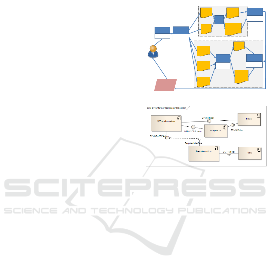
6 SUPPORTING TOOLS AND
MEASUREMENTS
In order to fully support our approach the BTrans-
former (Gonz
´
alez A., 2011) tool has been imple-
mented on top of the Eclipse platform (http://www.
eclipse.org) as a plugin. BTransformer allows a
business process designer to generate a specification
in CSP+T from a BPMN model. The tool allows for
the creation, the editing, the deleting and the storing
of a set of the transformation rules of BPMN 2.0 into
CSP+T. Since BTransformer tool is able to read in-
put/output models written in standard XML files, it
can be easily extended to encode BPMN 2.0 models
into other notations of which can be defined trans-
formation rules that are semantically sound. For in-
stance, the set of transformations of BPMN 2.0 into
LOTOS NT described in (Poizat P., 2012) have been
recently used to extend the output models generated
by BTransformer into LOTOS NT processes, which
is one of the input formats accepted by CADP Tool-
box (Garavel A., 2011) for checking BP models real-
izability and verification (Figure 11).
BTransformer permits to automatically generate
formal specifications in several process languages,
such as CSP+T and LOTOS NT, and business pro-
cess orquestation languages as WS-BPEL. BTrans-
former is based on the model tranformation language
ATLAS (ATL) (Jouault F., 2008) and is implemented
as an Eclipse plugin, which is capable of trasform-
ing BPMN 2.0 models designed with the editor Intalio
(http://www.intalio.com) into output files of dif-
ferent formats. A UML class diagram that shows the
components of the plugin that provides the function-
ality of BTransformer tool is shown in Figure 12. A
detailed description of BTransformer implementation
is given in (Gonz
´
alez A., 2011).
BPMN 2.0
Choreographies
Temporal
constraints
Encoding
BTransformer
Model
Checking
FDR-3
Model
Transform.
CAESAR
REDUCTOR
Realizability
Verification
EVALUATOR
BISIMULATOR
CSP+T
processes
CCTL
scripts
LOTOS NT
processes
SVL
scripts
WS-BPEL
code
Peers
Models
(LTS)
Intended
Choreo
graphy
(LTS)
CADP Toolbox
Peers
Models
(bpmn)
Choreography
specification
(automaton)
‘Reific
ation’
FDR (Formal Systems)
Feedback
( A )
( B )
Figure 11: Software tools support.
Figure 12: BTransformer Tool Components.
The BPMN model and case study used to as-
sess the results on the choreography realization
model checking and the operation of the implemented
BTransformer tool were taken from the “Logistic Pro-
cess in Hospitals’ (Baacke L., 2009). A series of
heuristics or criteria have been defined in order to de-
tect inconsistencies between the notational BPMN el-
ements in the source model and processes generated,
according to our proposal, for the target model :
- Completeness: all elements in the source BPMN-
model diagram appear reflected in their semanti-
cally equivalent specifications as process terms.
- Number of processes: there is at least one process
activity defined in the diagram.
- Completeness of relations: it is possible to estab-
lish relationships between two processes as long
as they present a relationship between two or more
activities in the model.
- Behavioral safety: the set of execution sequences
of the processes in the specification must be in-
cluded (or coincide with) in the set of sequences
of the model.
Table 1 shows the results obtained by applying the
consistency criteria to the CSP+T encoding obtained
with BTranformed tool for the complete case study.
Checking Realizability of a Timed Business Processes Choreography
419

Table 1: Results of tests obtained with BTransformer tool.
Model
Comple- Number of Comple- Behav-
teness of processes teness of ioural
elements relations safety
Hospital X 22 X X
Logistics
7 CONCLUSION
In order to enforce the realization of feasible chore-
ographies within the realm of business proceses, we
have presented a feasible formalization of a subset of
BPMN 2.0 constructs.
Consequently, a possible solution to the chore-
ography realization problem is presented here by
encoding BCD (BPM 2.0 Choreography Diagrams)
modelling-entities into a proces calculus named
CSP+T. In this way, we can analyze and automatically
verify the realizability of a defined choreography into
services that communicate through messages in a gen-
eral, distributed, and highly parallel system.
In a longer term perspective, we also aspire to de-
velop supporting tools for business analysts and mod-
elers to find a way to improve the quality of their busi-
ness models.
REFERENCES
Aalst, W. (2009). Challenges in business process anal-
ysis. In In: Enterprise Information Systems. Lec-
ture Notes in Business Information Processing, v. 12,
27:42. Springer, Berlin, Heidelberg.
Arkin A., Askary S., e. (2005). Committee draft. In Ser-
vices Business Process Execution Language Version
2.0. WS-BPEL TC OASIS.
Baacke L., Mettler T., R. R. (2009). Component-based pro-
cess in health care. In In:17th European Conference
on Information Systems.
Bezem M., Klop J.W., R. d. V. (2003). “Terese”. Term
rewriting systems. Cambridge University Press.
Capel M.I., M. L. (2014). Choreography modeling compli-
ance for timed business models. In In: Barjis J., Pergl
R. (eds) Enterprise and Organizational Modeling and
Simulation. EOMAS 2014. Lecture Notes in Business
Information Processing, vol 191, 202:218.
Cerone, A. (2002). From process algebra to visual lan-
guage. In Proceedings of the Conference on Appli-
cation and Theory of Petri Nets: Formal Methods in
Software Engineering and Defence Systems, v. 12.
Dongen B., A. W. (2004). Multi–phase process min-
ing: Building instance graphs. In In: Conceptual
Modeling–ER 2004. Lecture Notes in Computer Sci-
ence, v. 3288, 362:376. Heidelberg:Springer.
FormSys (2005). Failures–Divergence Refinement – FDR2
User Manual. Formal Systems Europe Ltd, Oxford,
2nd edition.
Garavel A., e. a. (2011). Cadp 2010: A toolbox for the
construction and analysis of distributed processes. In
Proceedings of TACAS’11,v.6605 of LNCS, 372:387.
Springer.
Gonz
´
alez A., Mendoza L.E., C. M. (2011). Btransformer: A
tool for bpmn to csp+t transformation. In Proceedings
of the 13th International Conference on Enterprise In-
formation Systems (ICEIS), Volume 3, Beijing, China,
8-11 June, 2011. ScitePress.
Jouault F., Allilaire F., e. a. (2008). Atl: A model tranfor-
mation tool. In Science of Computer Programming,
72, 31:39.
Ma S., Zhang L., H. J. (2008). Towards formalization and
verification of unified business process model based
on pi calculus. In Proceedings ACIS International.
Conference on Software Engineering Research, Man-
agement and Applications 1.
Mendoza L.E., Capel M.I., P. M. (2012). Concep-
tual framework for business processes compositional
verification. Information and Software Technol-
ogy,54,149:161.
Milner, R. (Prentice-Hall). Communication and Concur-
rency (International Series in Computer Science). The
publishing company.
OASIS (2007). Web Services Business Process Ex-
ecution Language Version 2.0. http://docs.oasis-
open.org/wsbpel/2.0/wsbpel-v2.0.pdf.
OMG (2011). Business Process Model and Notation
(BPMN)–version 2.0.
Poizat P., S. G. (2012). Checking the realizability of bpmn
2.0 choreographies. In TEMPLATE’06, 1st Interna-
tional Conference on Template Production.In: 27th
Simposium of Applied Computing, 1927:1934, Riva
del Garda(Italy), March 25-29. ACM.
Puhlmann, F. (2007). Soundness verification of business
processes specified in the pi-calculus. In Lecture
Notes in Computer Science, no.4803: 6-23. Elsevier.
Rozinat A., A. W. (2006). Conformance testing: Measuring
the fit and appropriateness of event logs and process
models. In In: Business Process Management Work-
shops. Lecture Notes in Computer Science. Elsevier.
Schneider, S. (2000). Concurrent and Real–Time Systems –
The CSP Approach. John Wiley & Sons, Ltd.
Thatte, S. (2001). XLANG: Web Services for Business Pro-
cess Design.Microsoft Corporation, 2001.
W3C (November 9, 2005). W3c candidate recommenda-
tion. In Web Services Choreography Description Lan-
guage Version 1.0. http://www.w3.org/TR/ws-cdl-10/.
Wong P.Y.H., G. J. (2008). A process semantics for bpmn.
In International Conference on Formal Engineering
Methods, ICFEM 2008 (Kitakyushu-City), Japan, Oc-
tober 27-31, 2008. In Lecture Notes in Computer Sci-
ence 5256, 355:374. Heidelberg:SpringerS.
Zic, J. (1994). Time–constrained buffer specifications
in csp+t and timed csp. In ACM TOPLAS,16(6),
1661:1674. ACM.
CLOSER 2017 - 7th International Conference on Cloud Computing and Services Science
420
