
XIS-Reverse: A Model-driven Reverse Engineering Approach for Legacy
Information Systems
André Reis and Alberto Rodrigues da Silva
INESC-ID, Instituto Superior Técnico, Universidade de Lisboa, Lisbon, Portugal
Keywords:
Model-driven Engineering, Model-driven Reverse Engineering, Model-driven Reengineering, Database,
Legacy System.
Abstract:
Due to the development of new technologies companies face high costs managing and maintaining their legacy
applications, thus upgrading those systems became a complex challenge. This paper describes a model-driven
reverse engineering approach that aims to support the mentioned challenge. This approach takes as input the
legacy relational database schema, but also user preferences to better guide the reverse engineering process.
From these artefacts it is possible to extract models of the legacy application through model-to-model transfor-
mations based on a set of well defined rules and heuristics. The main contributions of this proposal (compared
with the state of the art) are the semi-automatic identification of generalizations and aggregations and the
possibility to automatically extract default values to enrich the produced models. The paper also includes an
evaluation and a discussion of the proposal based on a simple case study and a real-world application.
1 INTRODUCTION
Enterprises have to manage legacy software applica-
tions which were built in the past and are still being
used since then. In the long term the maintenance of
such applications become rather complex, mainly due
to outdated or poor documentation and reduced flexi-
bility of the original software technologies (De Lucia
et al., 2008). To overcome these problems software
reengineering approaches can be used (Arnold, 1993).
Reengineering supports evolutionary maintenance of
legacy applications by analysing and modifying such
applications rebuilding them in a new form (Chikof-
sky and Cross, 1990).
A model-driven engineering (MDE) approach can
be seen as a chain of model transformations that pro-
duces the target software artefacts from more abstract
models (Ruiz et al., 2016). Using this kind of ap-
proach, the most common model transformations are:
Model-to-Model (M2M) and Model-to-Text (M2T)
(da Silva, 2015). M2M transformations generate a tar-
get model from a source model. M2T transformations
produce a textual representation from a source model.
Model-driven reengineering is the application of
MDE principles and techniques to reengineer an ap-
plication. As illustrated in Figure 1, a complete
model-driven reengineering process is composed of
three main stages (Chikofsky and Cross, 1990): (i) re-
verse engineering, (ii) restructuring and (iii) forward
engineering. First, the reverse engineering stage aims
to extract knowledge defined in low abstraction rep-
resentations through introspection and analysis of the
initial source artefacts (initial models); this process
collects valuable information that makes it easier to
define current legacy application requirements. Sec-
ond, the system restructuring stage involves establish-
ing a mapping between the source and the target sys-
tems. Third, the forward engineering stage produces
the artefacts to the new target system. Each of these
stages is a transformational process that can be im-
plemented by means of a model transformation chain
whose initial set of models is injected. This model
injection is performed with a T2M transformation ap-
plied to textual software artefacts, such as SQL data
definition language (DDL) scripts (Ruiz et al., 2016).
Model-Driven Reverse Engineering (MDRE) uses
MDE principles and techniques to reverse engineer-
ing, producing relevant (model-based) views from
legacy systems, thus facilitating their understand-
ing and subsequent manipulation (Bruneliere et al.,
2014). A MDRE process is a part of the model-driven
reengineering process merely focused in the reverse
engineering stage.
This paper proposes a MDRE approach to produce
high-level specifications of legacy information sys-
tems in a human-controlled way. These specifications
196
Reis A. and Rodrigues da Silva A.
XIS-Reverse: A Model-driven Reverse Engineering Approach for Legacy Information Systems.
DOI: 10.5220/0006271501960207
In Proceedings of the 5th International Conference on Model-Driven Engineering and Software Development (MODELSWARD 2017), pages 196-207
ISBN: 978-989-758-210-3
Copyright
c
2017 by SCITEPRESS – Science and Technology Publications, Lda. All rights reserved
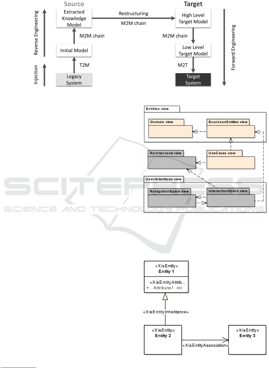
Figure 1: Model-driven reengineering process.
are defined according to domain specific languages,
and produced from the injection and the reverse engi-
neering stages.
The remainder of the paper is organized as fol-
lows. Section 2 gives a brief introduction of the con-
text of this research. Section 3 describes the proposed
MDRE approach and associated tool. Section 4 dis-
cuss the main results using a simple case study and
also a real-world application. Section 5 analyses and
compares this proposal with the related work. Finally
section 6 presents the conclusion and future work.
2 BACKGROUND
This research has been developed at the Instituto Su-
perior Técnico, Universidade de Lisboa, in the area of
MDE, namely within the MDDLingo
1
initiative.
MDDLingo is an umbrella researching initiative
that aggregates several projects around MDE topics,
namely involving the definition of a family of lan-
guages, also known as XIS*. This set of modelling
languages derives from XIS-UML profile (da Silva,
2003), involving namely XIS-Mobile (Ribeiro and
da Silva, 2014b; Ribeiro and da Silva, 2014a), XIS-
CMS (Filipe et al., 2016) or XIS-Web (Seixas, 2016).
XIS-UML is a set of coherent constructs defined as
a UML profile that allows a high-level and visual
modeling way to design business information sys-
tems. In general these languages include the fol-
lowing views: Entities (which includes Domain and
Business Entities views), UseCases (containing Ac-
tors and Use Cases views), Architectural and User-
Interfaces (composed by Interaction Space and Nav-
igation Space views). Figure 2 illustrates the afore-
mentioned set of views
Figure 3 illustrates a very simple XIS* Domain
1
https://github.com/MDDLingo
Figure 2: The multi-view organization of XIS*.
view which aggregates domain classes (XisEntity),
their attributes (XisEntityAttribute) and relationships
(XisEntityAssociation/XisEntityInheritance).
Figure 3: XIS* Domain view.
XIS-Reverse: A Model-driven Reverse Engineering Approach for Legacy Information Systems
197
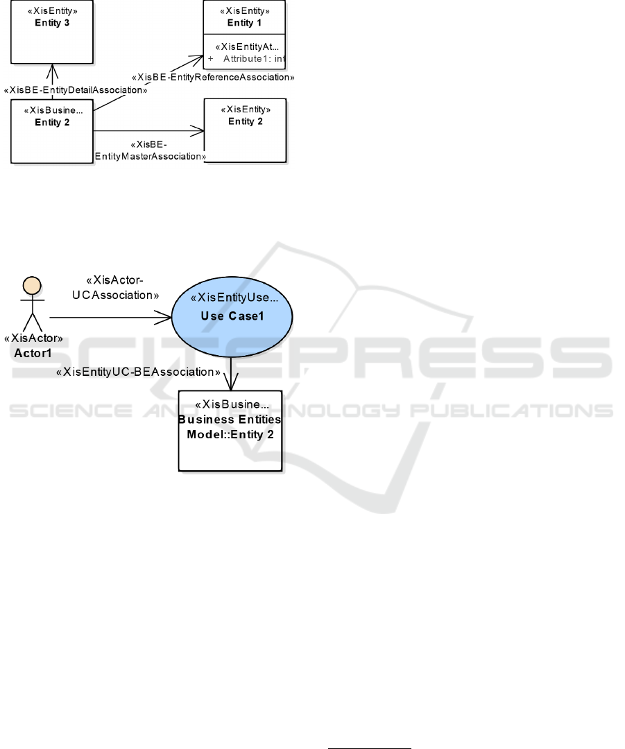
In addition, Figure 4 shows the BusinessEntities
view which allows to define higher-level entities (Xis-
BusinessEntity), that aggregate XisEntities and that in
the context of a given use case are easily manipulated.
Figure 4: XIS* BusinessEntities view.
Finally, Figure 5 shows the UseCases View. This
details the operations an actor can perform when in-
teracting with the application in the context of a busi-
ness entity (Ribeiro and da Silva, 2014b).
Figure 5: XIS* UseCases view.
XIS* languages are very alike in terms of the
Entities view, however there are some discrepancies
on their Use Cases, Architectural and User-Interfaces
views due to each platform target application. For
example, XIS-CMS does not have an Architectural
view.
It is to point out that all of them are able to gen-
erate their User-Interfaces, using a smart approach
based on M2M transformations given the set of Do-
main, Business Entities, (Architectural,) Actors and
Use Cases views.
3 XIS-REVERSE APPROACH
The MDRE approach proposed in this paper is named
“XIS-Reverse”. This approach focus only in the first
two stages of the reengineering process (Figure 1), na-
mely Injection and Reverse Engineering stages. XIS-
Reverse is generically represented in Figure 6. It
starts by extracting the application database schema
from an existent data source (through injection).
Thereafter the Application data model is generated.
Secondly, the user is able to define his own prefer-
ences by tweaking some heuristic’s parameters, pro-
ducing the XIS-Reverse configuration. The reverse
engineering stage takes as input these two artefacts,
and generates XIS* models. Then, the designer can
analyse the produced artefacts and introduce some re-
finements, such as changing automatically identified
relationships into different ones in the Entities view,
enhancing the Use-Cases views, etc.
3.1 Tools Support
Since Sparx Systems Enterprise Architect (EA)
2
is
the tool used to design business information systems
in the other XIS* projects, in order to reduce depen-
dencies for future work and learning curve for the
user, we decided to also implement XIS-Reverse on
top of this tool. Moreover, from this tool we used a
set of provided technologies, namely the Automation
Interface and the Model Driven Generation
3
.
Both reverse engineering configuration and exe-
cution steps (Figure 6) are supported by the XIS-
Reverse tool. Moreover, in terms of the applica-
tion database access and the profiler log file injec-
tion, for now this tool only supports SQL Server
connections and profiler log files generated from
the Microsoft SQL Server Management Studio Pro-
filer Tool. Regarding the produced specifications,
this tool is able to produce XIS* models but also
RSLingo’s RSL
4
(de Almeida Ferreira and da Silva,
2012; de Almeida Ferreira and da Silva, 2013) spec-
ifications. However, due to space constraints, only
XIS*/XIS-Web models are considered. Furthermore,
this tool can be extended to support different repre-
sentations.
3.2 Running Example
For better understanding and simplicity of the expla-
nation, we introduce a simple but practical example:
the Social Security legacy application (SS-App).
The SS-App consists in an application that man-
ages beneficiaries, their dependents (and tutors), as-
sociated documents and user accounts.
This domain is modelled as 8 tables: Beneficiary
and Dependent which primary keys are foreign keys
2
http://www.sparxsystems.com/products/ea
3
http://www.sparxsystems.com/resources/mdg_tech
4
https://github.com/RSLingo/RSL
MODELSWARD 2017 - 5th International Conference on Model-Driven Engineering and Software Development
198
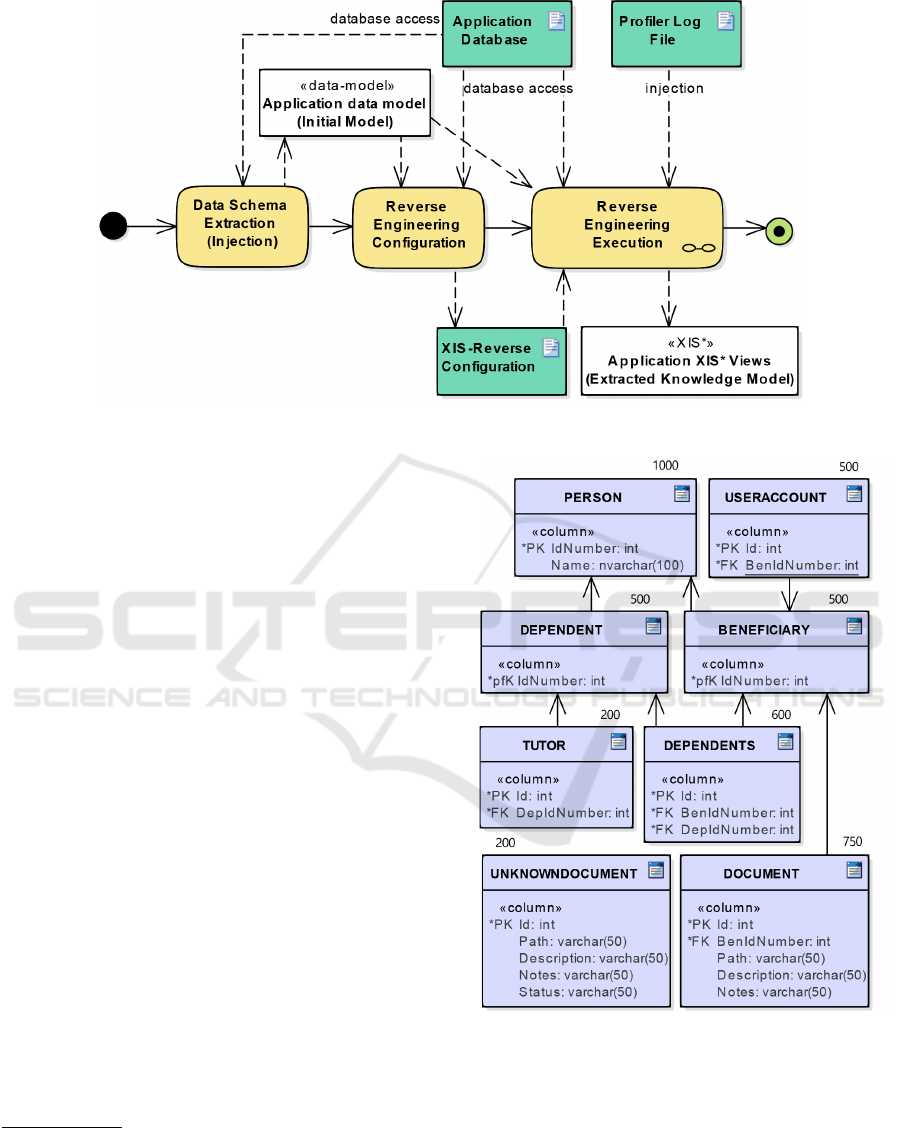
Figure 6: Overview of the XIS-Reverse approach.
to a Person table. Dependents table represents the
relationship between a Beneficiary and a Dependent
(through its foreign keys linked to each of those ta-
bles). A Dependent may have a Tutor, which are
linked by a foreign key. Each Beneficiary has a set
of documents (since a Document has a foreign key to
a Beneficiary table) and a unique UserAccount (due
to the unique constraint that the UserAccount table
has over its BenIdNumber foreign key). Furthermore,
several documents not linked to any Beneficiary may
exist as an UnknownDocument.
Each of those tables, columns, constraints and
number of rows in the database are represented in Fig-
ure 7.
3.3 Data Schema Extraction
Following the aforementioned process of Figure 6,
during the Data Schema Extraction step, in order to
extract the application data model our approach de-
pends on the EA native capability
5
to reverse engi-
neer a database model through an ODBC connection.
Moreover, EA supports several ODBC data sources
6
.
3.4 Reverse Engineering Configuration
A snapshot of the tool is illustrated in Figure 8, which
is used to explain the main configuration features.
5
http://www.sparxsystems.com/enterprise_architect
_user_guide/13.0/model_domains/
importdatabaseschemafromod.html
6
http://www.sparxsystems.com/enterprise
_architect_user_guide/13.0/model_domains/
supported_databases.html
Figure 7: Case Study SS-App data model.
The configuration panel of the tool has four main ar-
eas: input, output, transformation rules guidance and
appearance.
The Input area allows to specify the root node to
where the application data model was extracted, to in-
troduce the database name and to choose how to en-
hance the output specifications. In the Output area
the user can select additional output representations,
XIS-Reverse: A Model-driven Reverse Engineering Approach for Legacy Information Systems
199
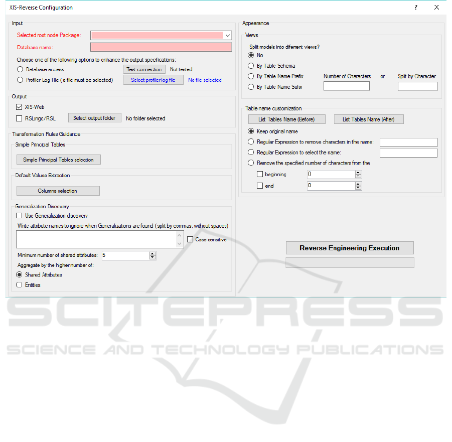
Figure 8: Configuration panel of the tool.
namely XIS-Web or RSLingo’s RSL representations.
The Transformation Rules Guidance area allows
the user to contribute with his knowledge to enhance
the Reverse Engineering process. This configuration
can be split into three areas: (i) Simple Principal Ta-
bles (ii) Default Values Extraction and (iii) General-
ization discovery. The user can select which tables
are Simple Principal Tables (which we consider as ta-
bles without many relationships, such as configura-
tion tables or “kind of” tables). Moreover, the user
can enhance the produced specifications by extracting
defaults values from a selected column of a certain ta-
ble. Furthermore, in both cases the user can also filter
the list of tables by specifying the maximum number
of rows per table, which allows the user to find more
easily “kind of” tables, since usually they have few
number of instances (rows). Finally, the user can acti-
vate generalization discovery and add some knowl-
edge, such as a list of XisEntityAttribute names to
ignore, the minimum number of shared XisEntityAt-
tributes (e.g. 5 or 10), and to choose how to aggregate
those entities (e.g. by the higher number of shared
attributes or by the higher number of aggregated enti-
ties).
The Appearance configuration area allows to im-
prove readability of the produced specifications, by
arranging models into smaller views and changing the
name of the tables to a clearer one.
3.5 Reverse Engineering Execution
Taking as input (i) the application data model, (ii) the
XIS-Reverse configuration and (iii) the profiler log
file or the database connection, the reverse engineer-
ing process is composed by a set of transformation
tasks, that will be applied. Those include a chain of
M2M transformations which are used to specify the
application as a set of XIS* views.
3.5.1 Initialization
Before M2M transformations take place, the profiler
log file or the database connection, if provided, are
used to extract more detailed information about the
legacy application, that may enhance the produced
specifications.
From the profiler log file it is possible to extract
SQL statements (INSERT, SELECT, UPDATE and
DELETE), and from those statements the set of used
tables. Moreover, from that we generate 4 different
lists, one for each type of statement, where each one
MODELSWARD 2017 - 5th International Conference on Model-Driven Engineering and Software Development
200

of them holds for each table the number of occur-
rences for the corresponding kind of statement.
A database connection can be used to collect for
each table in the initial application model, the current
number of rows in the actual application database.
3.5.2 XIS Model-to-model Transformations
The following transformations are broken down into
the different set of produced elements.
XisEntities Transformation Rules.
For each table of the source data model, the following
XisEntities (E i) rules are applied:
(E 1) If a table has only 2 foreign keys, each one
to a distinct table, and does not contain more at-
tributes (excluding its primary keys), this table
will be translated into a XisEntityAssociation be-
tween the two referenced tables, using a many-to-
many cardinality, ie. *:* cardinality (e.g. Depen-
dents in the running example).
(E 2) Otherwise the table will map a XisEntity (e.g.
Beneficiary in the running example).
XisEntityAttribues Transformation Rules.
Regarding table columns, the following XisEntityAt-
tribues (EA j ) rules are applied:
Let A, B be two tables related by a foreign key
constraint from B (referencing table) to A (referenced
table):
(EA 1) For the complete Primary Key:
a) If all the foreign key columns in B are also its
complete primary key, in other words B and
A have a 1:1 relationship since B primary key
references A primary key. Then B foreign
keys will be translated into a XisEntityInheri-
tance relationship, where the class equivalent
to A will be the superclass and the equivalent
class to B will be the subclass (e.g. Person
(A) and Beneficiary (B) in the running exam-
ple).
b) Otherwise, the complete Primary Key will
not be represented (e.g. UnknownDocument
in the running example). Due to XIS* Do-
main View similarity to a Class Diagram,
each XisEntity can be seen as a Class, which
can have objects, and each object is different
by definition, so there is no need for a unique
identifier for each XisEntity.
(EA 2) For the remaining columns with Foreign Key
constraints:
a) If the foreign key in B constitute a unique in-
dex the XisEntityAssociation will have a 1:1
cardinality, preserving the relationship direc-
tion (e.g. BenIdNumber of UserAccount in
the running example).
b) If A was not selected as Simple Principal Ta-
ble by the user (configuration stage), and one
of the following options is also true: 1) the
profiler log file was provided, both A and
B tables were referenced in that file, and ta-
ble B had the same or higher amount of IN-
SERT operations as A did, or 2) the database
connection was provided and table B had the
same or higher amount of rows as A did (if
B foreign key column allows NULL values,
only rows with NOT NULL values on that
column will be taken into account). Then we
assume that there is an aggregation relation-
ship between entity A and B (A aggregates
B), that is translated into a XisEntityAsso-
ciation, preserving the foreign key cardinal-
ity and represented with a bidirectional arrow
(e.g. Beneficiary with 500 rows (A) and Doc-
ument with 1000 rows (B) in the running ex-
ample).
This reasoning made sense for us since that,
assuming that A and B are respectively strong
and weak entities, A is the one which aggre-
gates B, it is fair to assume that if that foreign
key was made for that purpose, then there
must be at least the same amount of B in-
stances created compared with A.
c) Otherwise, the XisEntityAssociation will
have a 1:* cardinality between table B and
A, preserving the relationship direction (e.g.
Dependent (A) and Tutor (B) in the running
example).
(EA 3) Otherwise the column will be translated into a
XisEntityAttribute with a corresponding XIS* at-
tribute type following a predefined mapping (e.g.
Name from table Person in the running exam-
ple). Moreover, if previously configured, the user
can explicitly select if default values from a cer-
tain XisEntityAttribute from a particular XisEn-
tity should be extracted and written as an annota-
tion, which will be linked to the XisEntity. This
feature is a significant contribution since the pro-
duced specifications are enhanced with those val-
ues, allowing a better understanding of the XisEn-
tities captured from the legacy domain.
Note: in both b) and c) cases, from (EA 2), when
the Not Null option is not set for that column (in other
words, that column can be NULL), the XisEntityAs-
sociation target’s cardinality is the concatenation of
0.. with the original target cardinality. (e.g. 1 was
XIS-Reverse: A Model-driven Reverse Engineering Approach for Legacy Information Systems
201

the original target cardinality and the column allowed
NULL values, then it becomes 0..1)
Further XisEntityInheritance Transformation
Rule.
For each XisEntity, after the previously mentioned
XisEntities and XisEntityAttributes rules are applied:
This XisEntityInheritance identification is per-
formed comparing every XisEntity and their XisEn-
tityAttributes with each other. We assume that two
XisEntityAttributes are the same if they share the
same name and type. During this comparison, if
previously defined, some XisEntityAttributes can be
excluded by their name. Moreover, we cluster 2
or more XisEntities if they share at least the same
or more predefined number of shared XisEntityAt-
tributes. Furthermore during this comparison only
XisEntities without inheritance relationship will be
taken into account.
After this clustering procedure, there are two ways
of finding inheritance, depending on the configura-
tion, the list can be ordered by the descending num-
ber of entities or ordered by the descending number
of shared XisEntityAttributes in each cluster. While
this list has clusters of XisEntities a Superclass is cre-
ated for each cluster. This Superclass will have the
identified XisEntityAttributes, each of the XisEntities
in that cluster will be linked to the superclass using a
XisEntityInheritance and will not own the XisEntity-
Attributes that their Superclass has (e.g. Unknown-
Document and Document share 3 identical columns
(Path, Description and Notes) in the running exam-
ple).
In order to implement the first phase of this
algorithm, given the complexity that is comparing
every XisEntity with each other taking into account
all their XisEntityAttributes, in domains that can
easily be compound by hundreds or thousands of
elements, we based our approach in the MapReduce
(Dean and Ghemawat, 2008) programming model
which allows to handle large data sets.
XisBusinessEntities Transformation Rules.
For each XisEntity, the following XisBusinessEntity
(BE k ) rules are applied:
(BE 1) If the current XisEntity aggregates other
XisEntities or is not aggregated by another XisEn-
tity (i.e. we do not consider weak entities as
Business Entities), then a corresponding XisBusi-
nessEntity will be created, followed by the cre-
ation of a XisBE-EntityMasterAssociation that
will link that XisBusinessEntity with its XisEntity
from the Domain view, and for each XisEntityAs-
sociation:
a) If the XisEntityAssociation is an aggre-
gation then it will be translated into a
XisBE-EntityDetailAssociation between that
XisBusinessEntity and the target XisEn-
tity of the XisEntityAssociation. More-
over, if the corresponding target XisBusi-
nessEntity exists, there will be a XisBE-
EntityReferenceAssociation between the tar-
get XisBusinessEntity and the source XisEn-
tity.
b) Otherwise it will be translated into a
XisBE-EntityReferenceAssociation between
that XisBusinessEntity and the target XisEn-
tity of the XisEntityAssociation.
(BE 2) Otherwise there is no mapping.
XisEntityUseCases Transformation Rules.
For each XisBusinessEntity there will be a corre-
sponding elementary XisEntityUseCase that is named
"Manage" followed by the XisBusinessEntity master
XisEntity name, associated to the XisBusinessEntity
by a XisModule-BEManageAssociation. And a de-
fault XisActor will be linked to the XisEntityUseCase
using a XisRole-ModuleAssociation.
4 EVALUATION
In this section a real-world Social Security legacy ap-
plication (SS-App) will be used as the case study.
Firstly, due to the extension of this paper a simplified
version of the SS-App (described in the Subsection
3.2) will be used to show the produced specifications
with our tool. Secondly, the results of using our tool
with the whole version of this application will be fur-
ther shown and analysed.
4.1 A Simple Example
Taking as input the specified running example SS-
App data model, selecting database access to en-
hance the output specifications, selecting Status col-
umn from UnknownDocument to extract its default
values and activating generalization discovery by the
higher number of shared attributes with the minimum
of 3 attributes, Figure 9 shows the produced XIS* Do-
main view. For this image only the main contributions
of this paper were taken into account.
From the aforementioned configurations it was
possible to detect an aggregation between Beneficiary
and Document through (EA 2) b). Moreover, a super-
class with the shared attributes was created for Doc-
ument and UnknownDocument entities, through the
further XisEntityInheritance transformation rule. And
MODELSWARD 2017 - 5th International Conference on Model-Driven Engineering and Software Development
202
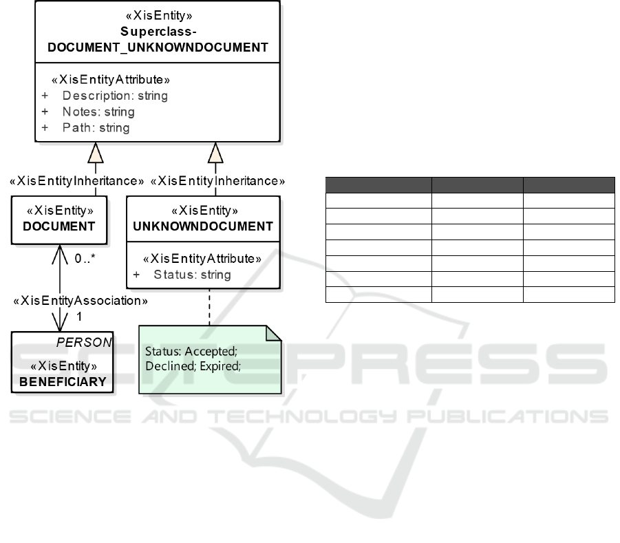
finally, a note was created and linked to the Unknown-
Document entity displaying the default values that the
Status column had in the database, through (EA 3).
Figure 9: Case Study SS-App XIS* Domain view.
4.2 A Real-world Example
During our research we had the chance to apply this
approach to a real-world legacy application, in order
to evaluate how much knowledge we could extract
from it.
This legacy database was from a Social Security
application and had 187 tables.
To reverse engineer this database we tried differ-
ent configurations, from which we are going to stress
two. Both used database access to enhance output
specifications and generalization discovery activated
by the higher number of shared attributes, with a mini-
mum of 5 shared attributes. Moreover, after analysing
the database we identified 5 often used attributes, each
one of them with same name and type in almost every
table. Thus, those 5 attributes were included in the
list of attribute names to ignore, in order to decrease
the generalization discovery time and try to produce
more interesting results, instead of a superclass that
would generalize almost every entity. The differ-
ence between the two configurations were in terms of
Simple Principal Tables selection. Although, in the
Experiment-A we did not select Simple Principal Ta-
bles, in Experiment-B we did.
Table 1, shows the main results of those two con-
figurations (Experiment-A and Experiment-B) with
the following metrics: number of XisEntities (in-
cluding explicit and implicit superclasses); number
of XisAssociations (also including Aggregations and
Many-to-many associations); the number of Aggre-
gations; number of Many-to-many associations; num-
ber of explicit superclasses; number of implicit super-
classes (through Generalization discovery) and num-
ber of XisBusinessEntities.
Table 1: Main results from reverse engineering process with
a real-world Social Security application.
Experiment-A Experiment-B
Entities 174 174
Associations 205 205
Aggregations 126 43
Many-to-many 19 19
Exp superclasses 0 0
Imp superclasses 4 4
BusinessEntities 140 156
After the Experiment-A reverse engineering, we
were mainly surprised with the amount of Aggrega-
tions detected (more than 60% of all Associations).
Then we explored more the database and concluded
that almost every foreign key from a main entity (e.g.
Beneficiary) to a configuration entity, was mistakenly
transformed into an aggregation from the configura-
tion entity to the main entity.
Thus, in order to discard such aggregations, in
the Experiment-B configuration we selected every en-
tity with at most 20 rows per table in the database
as a Simple Principal Table. Then the number of
aggregations reduced to around 20% of all Associa-
tions, and after analysing such aggregations against
the database, most of them made sense to be classified
as aggregations (e.g. Beneficiary aggregates Activity
Logs).
We did not further explored different general-
ization discovery configurations, since the minimum
number of shared attributes was already too low. Thus
we assumed that 4 implicit superclasses was already
a good result.
5 RELATED WORK
Reverse engineering of software applications have
been extensively studied in the last decades, and their
main contributions have been crucial to produce bet-
ter results in this complex activity, and furthermore
XIS-Reverse: A Model-driven Reverse Engineering Approach for Legacy Information Systems
203

to stimulate the development of reverse engineering
tools. More recently, MDE started to be applied to
reverse engineering (MDRE), promoting a more sys-
tematic and flexible process. Moreover, MDRE ap-
proaches have been extended in order to completely
reengineer a source application into a new target ap-
plication through model-driven reengineering tech-
niques.
This section overviews the most relevant research
studies, covering data schema extraction and reverse
engineering of databases. Moreover, those contribu-
tions are also compared with our approach.
5.1 Data Schema Extraction
The main properties of the research works analysed
in this subsection are shown in Table 2. This table
specifies for each approach, its input, the existence of
data schema extractors, if it extracts all table proper-
ties and its output. The last row categorises our ap-
proach.
Gra2MoL (Izquierdo et al., 2008) Text-to-Model
(T2M) language and MoDisco (Bruneliere et al.,
2014) framework have been specially tailored for data
schema extraction (model injection). Gra2MoL is a
Domain Specific Language (DSL) to write transfor-
mations between any textual artefact which conforms
to a grammar (e.g. source code) and a model which
conforms to a target metamodel. On the other hand,
MoDisco is a Java framework intended to facilitate
the implementation of MDRE approaches. Regard-
ing to data schema extraction, MoDisco facilitates the
implementation of discoverers (model injectors), and
it currently provides discoverers for Java, JSP and
XML. A drawback for both approaches is that they
would require the definition of such transformations
and discoverers, respectively, to extract the database
schema.
Schemol (Díaz et al., 2013) is another tool for
injecting models. However, this tool allows inject-
ing data stored into database by specifying transfor-
mations that express the correspondence between the
source database schema and the target metamodel.
Furthermore, in terms of database model injec-
tion (to ease this T2M transformation) it is possi-
ble to transform a database schema into a graphi-
cal representation using a variety of commercial and
academic tools. DB-MAIN (Hainaut et al., 1994)
and SQL2XMI (Alalfi et al., 2008) are two exam-
ples of such academic tools. Firstly, DB-MAIN is
a toolbox that supports database reverse engineer-
ing, and includes legacy database schemas extractors,
through several sources such as ODBC drivers or SQL
files. Secondly, SQL2XMI is entitled as a lightweight
transformation of data models from SQL Schemas to
UML-ER expressed in XMI. To our knowledge, this
tool is still limited compared with DB-MAIN since
it does not infer entity types or cardinalities, and for
now it is only compatible with the MySQL implemen-
tation of the SQL DDL.
To sum up, given that a set of existing tools al-
ready support data schema extraction from several
sources, without additional specification of transfor-
mations, we took advantage of such tools, more pre-
cisely we used EA.
5.2 Reverse Engineering
A reverse engineering approach can be classified in
several ways. Table 3 gives a properties summary of
the thereafter analysed research works. These proper-
ties include: kind of analysis, output, the existence of
tools for automating the approach, automation level of
those tools in regards to the reverse engineering stage,
if the tool allows extension and main contributions (A
- Aggregations Extraction, G - Implicit Generaliza-
tion Extraction and V - Default Values Extraction).
Regarding reverse engineering techniques, sev-
eral approaches have been proposed, which are usu-
ally distinguished by the particular application arte-
fact used as main information source. The most rel-
evant research works, following such distinction, are
described below.
Schema analysis (Premerlani and Blaha, 1993)
is mainly focused on spotting similarities in names,
value domains and representative patterns. This tech-
nique may help identify missing constructs (e.g. for-
eign keys). Moreover, (Premerlani and Blaha, 1993)
specification of a manual process was adapted in
our approach to semi-automatically and automatically
identify generalizations and many-to-many associa-
tions, respectively.
Data analysis (Chiang et al., 1994; Pannurat et al.,
2010) uses content mined from a database. Firstly it
can be used to analyse the database normalisation and
secondly to verify hypothetical constructs suggested
by other techniques. Given the combinatorial explo-
sion that can affect the first approach, data analysis
technique is mainly used with the purpose of the sec-
ond approach. In addition, our approach uses this
technique in a similar way, however it is applied to
classify associations.
Screen analysis (Ramdoyal et al., 2010) state that
user interfaces can also be sources of useful informa-
tion. These user-oriented views over a database may
display spatial structures, meaningful names and, at
run time data population and errors combined with
data-flow analysis may provide information about
MODELSWARD 2017 - 5th International Conference on Model-Driven Engineering and Software Development
204
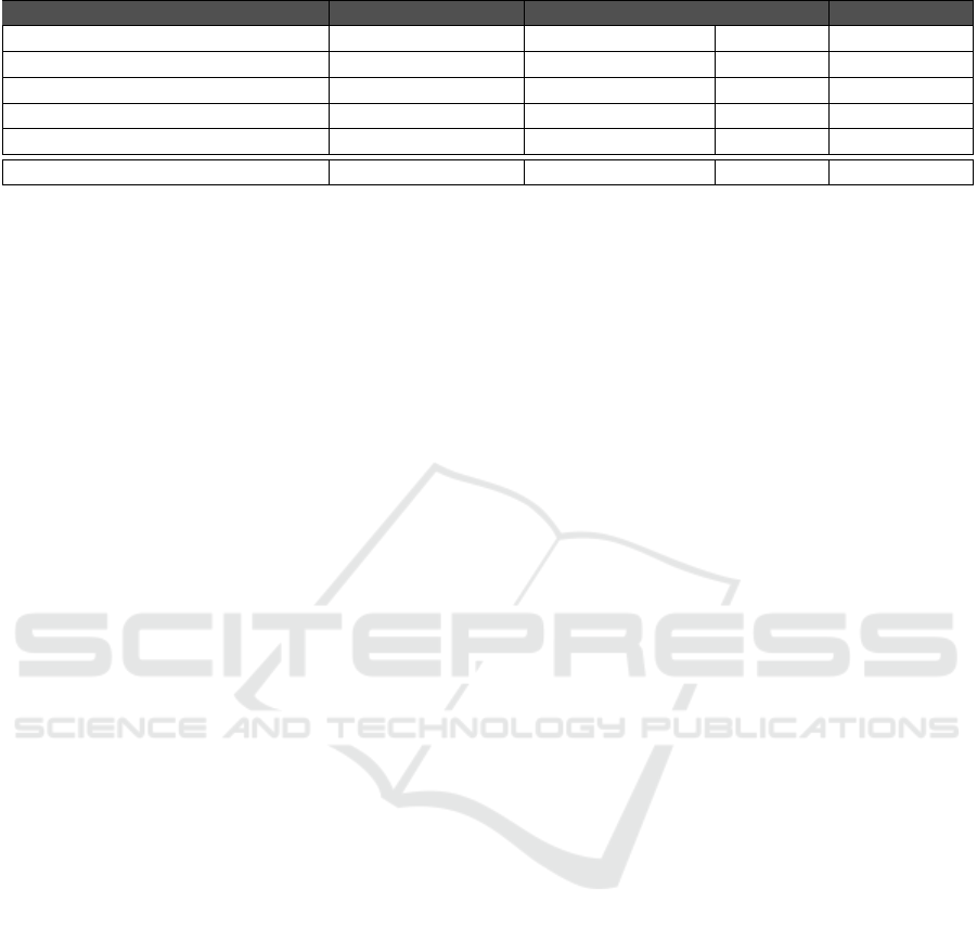
Table 2: Classification of some related works on data schema extraction.
Approach Input Schema Extractors Properties Output
Gra2Mol (Izquierdo et al., 2008) any textual artefact no n.a. any model
MoDisco (Bruneliere et al., 2014) several sources no n.a. any model
Schemol (Díaz et al., 2013) data stored into DB no n.a. any model
DB-MAIN (Hainaut et al., 1994) several sources yes (e.g. ODBC) yes GER
SQL2XMI (Alalfi et al., 2008) SQL DDL schema yes (only MySQL) no UML in XMI
EA (our approach) several sources yes (e.g. ODBC) yes UML
data structures and schema properties. Moreover, our
approach did not consider this kind of analysis.
Static (Petit et al., 1994; Di Lucca et al., 2000)
and Dynamic (Cleve et al., 2011a; Cleve et al., 2011b)
program analysis can easily give valuable information
about field structure and meaningful names, or iden-
tifying complex constraint checking and foreign keys
after a complex analysis. A main challenge of dy-
namic program analysis is the extraction of highly dy-
namic interactions between a program and a database.
Moreover, the analysis of SQL statements is one of
the most powerful variant of source code analysis.
Furthermore, our approach uses static program anal-
ysis in the profiler log file, aiming to classify associa-
tions.
Additionally, a set of approaches, concerning the
application of MDE, are also taken into account. Our
analysis focused on their injection and reverse engi-
neering stages.
As previously introduced, MoDisco MDRE
framework (Bruneliere et al., 2014) has a huge poten-
tial in order to support reverse engineering activities,
due to its generic and extensible properties. Besides
its legacy application discoverers (model injectors),
MoDisco also allows the definition of transformations
and generators, responsible for restructuring and for-
ward engineering tasks over the system models, re-
spectively. Our approach could be implemented ex-
tending this framework, however that would require
the definition from scratch of all the three stages (dis-
coverers, transformations and generators) needed to
produce the desired artefacts.
Polo et al. propose a method and a tool, called
Relational Web (Polo et al., 2007) specially designed
for database reengineering. The starting point is a re-
lational database, whose physical schema is reverse
engineered into a class diagram representing its con-
ceptual schema. In the restructuring stage, the class
diagram is manipulated by the user and then passed
as input to the forward engineering step. Moreover,
this tool supports the definition of new database man-
agers to be used as input and the implementation of
new code generators. Furthermore, on the one hand
this approach only uses as input the physical schema,
and user knowledge, and its tool does not take advan-
tage of the existing MDE techniques nor technologies.
However, this approach defined foreign key’s seman-
tic extraction techniques, to identify inheritance rela-
tionships and associations, that were adapted and ex-
tended by our approach, in order to identify aggrega-
tions.
As previously stated, DB-MAIN (Hainaut et al.,
1994) is a toolbox that offers a complete function-
ality with which to apply database reverse engineer-
ing. Regarding to reverse engineering DB-MAIN in-
cludes features such as extractors of legacy database
schemas, transformations between schemas, data and
code analysis tools, among others. This tool is one
of the most mature ones, in regard to database re-
verse engineering, meaning that it includes several
features that have been the result of a great number of
research contributions from Namur University. DB-
MAIN supports a lot of common transformations and
extraction tools thus, a user with such tools can han-
dle almost any needed transformation to create a good
conceptual schema. However, this tool will require
the user to apply all the needed transformations, thus
the degree of automation achieved in our approach is
higher. Furthermore, DB-MAIN supports generaliza-
tion representation, but once again it must be identi-
fied by the user.
Regarding to the main contributions of this paper,
we do not find any other approach that specializes as-
sociations (e.g. distinguishing between associations
and aggregations), nor any approach that allows to ex-
tract default values and their representation into the
target conceptual schema.
6 CONCLUSION AND FUTURE
WORK
This paper presented a model-driven reverse engi-
neering approach, named XIS-Reverse, applied to
legacy information systems. This approach provides
the opportunity to maintain and extend a given appli-
cation, even in cases that the related documentation is
outdated or missing. Moreover, XIS-Reverse is able
XIS-Reverse: A Model-driven Reverse Engineering Approach for Legacy Information Systems
205

Table 3: Classification of some works on reverse engineering.
Approach Analysis Output Tools Auto. Extension Contributions
(Premerlani and
Blaha, 1993)
schema OMT class
diagram
no n.a n.a. n.a.
(Chiang et al.,
1994)
data Extended ER no n.a n.a. n.a.
NoWARs (Pannurat
et al., 2010)
data Conceptual
schema
yes Semi n.a. n.a.
RAINBOW
(Ramdoyal et al.,
2010)
screen ER model yes n.a. n.a. n.a.
(Petit et al., 1994) program (static) Extended ER no n.a n.a. n.a.
(Di Lucca et al.,
2000)
program (static) Object-Oriented
class diagram
no n.a n.a. n.a.
(Cleve et al.,
2011a)
program
(dynamic)
n.a. yes n.a. n.a. n.a.
(Cleve et al.,
2011b)
program
(dynamic)
n.a. yes n.a. n.a. n.a.
Modisco
(Bruneliere et al.,
2014)
schema and
program (static)
KDM or UML yes Auto. yes n.a.
Relational Web
(Polo et al., 2007)
schema UML yes Auto. yes n.a.
DB-MAIN
(Hainaut et al.,
1994)
schema and
program (static)
GER yes Semi yes G
XIS-Reverse (our
approach)
schema, data and
program
XIS* and
RSLingo’s RSL
yes Semi yes A;G;V
to specify an application both as XIS* models and
as RSLingo’s RSL specifications. The main contri-
butions of this paper in terms of reverse engineering,
are focused in the implementation of semi-automatic
heuristics that can identify certain relationships be-
tween entities, namely aggregations and generaliza-
tions, and also the possibility to extract default values
from the source databases to enrich the target models
or specifications. This identification enables require-
ments enhancement, with less effort for the user by
using a tool that supports Reverse Engineering Exe-
cutions.
Regarding future work, in terms of extensibility
of the process we would like to evaluate the interop-
erability of the produced models with the XIS-Web
framework, for example, and analysing the similarity
of a forward engineered application from those mod-
els, allied with the smart approach of XIS* technolo-
gies, with the original legacy application. Addition-
ally, a divide-and-conquer approach could be used to
manage the complexity of identifying implicit gener-
alizations, splitting sets of entities by their schema,
for example.
ACKNOWLEDGEMENTS
This work was partially supported by national funds
under FCT project UID/CEC/50021/2013 and the
project TT-MDD-Mindbury/2015.
REFERENCES
Alalfi, M. H., Cordy, J. R., and Dean, T. R. (2008).
SQL2XMI: Reverse engineering of uml-er diagrams
from relational database schemas. In 15th Working
Conference on Reverse Engineering, pages 187–191.
IEEE.
Arnold, R. S. (1993). Software reengineering. IEEE Com-
puter Society Press.
Bruneliere, H., Cabot, J., Dupé, G., and Madiot, F.
(2014). Modisco: A model driven reverse engineer-
ing framework. Information and Software Technology,
56(8):1012–1032.
Chiang, R. H., Barron, T. M., and Storey, V. C. (1994). Re-
verse engineering of relational databases: Extraction
of an eer model from a relational database. Data &
Knowledge Engineering, 12(2):107–142.
MODELSWARD 2017 - 5th International Conference on Model-Driven Engineering and Software Development
206

Chikofsky, E. J. and Cross, J. H. (1990). Reverse engineer-
ing and design recovery: A taxonomy. IEEE software,
7(1):13–17.
Cleve, A., Meurisse, J.-R., and Hainaut, J.-L. (2011a).
Database semantics recovery through analysis of dy-
namic sql statements. In Journal on data semantics
XV, pages 130–157. Springer.
Cleve, A., Noughi, N., and Hainaut, J.-L. (2011b). Dy-
namic program analysis for database reverse engineer-
ing. In International Summer School on Generative
and Transformational Techniques in Software Engi-
neering, pages 297–321. Springer.
da Silva, A. R. (2003). The XIS approach and principles. In
29th Euromicro Conference, pages 33–40. IEEE.
da Silva, A. R. (2015). Model-driven engineering: A survey
supported by the unified conceptual model. Computer
Languages, Systems & Structures, 43:139–155.
de Almeida Ferreira, D. and da Silva, A. R. (2012).
RSLingo: An information extraction approach
toward formal requirements specifications. In
Model-Driven Requirements Engineering Workshop
(MoDRE), pages 39–48. IEEE.
de Almeida Ferreira, D. and da Silva, A. R. (2013). RSL-
IL: An interlingua for formally documenting require-
ments. In Model-Driven Requirements Engineering
(MoDRE), pages 40–49. IEEE.
De Lucia, A., Francese, R., Scanniello, G., and Tortora, G.
(2008). Developing legacy system migration methods
and tools for technology transfer. Software: practice
& experience, 38(13):1333.
Dean, J. and Ghemawat, S. (2008). Mapreduce: simplified
data processing on large clusters. Communications of
the ACM, 51(1):107–113.
Di Lucca, G. A., Fasolino, A. R., and De Carlini, U. (2000).
Recovering class diagrams from data-intensive legacy
systems. In Software Maintenance, 2000. Pro-
ceedings. International Conference on, pages 52–63.
IEEE.
Díaz, O., Puente, G., Izquierdo, J. L. C., and Molina, J. G.
(2013). Harvesting models from web 2.0 databases.
Software & Systems Modeling, 12(1):15–34.
Filipe, P., Ribeiro, A., and da Silva, A. R. (2016). XIS-
CMS: Towards a model-driven approach for develop-
ing platform-independent cms-specific modules. In
MODELSWARD’2016. SCITEPRESS.
Hainaut, J.-L., Englebert, V., Henrard, J., Hick, J.-M., and
Roland, D. (1994). Database evolution: the DB-
MAIN approach. In International Conference on Con-
ceptual Modeling, pages 112–131. Springer.
Izquierdo, J. L. C., Cuadrado, J. S., and Molina, J. G.
(2008). Gra2mol: A domain specific transformation
language for bridging grammarware to modelware
in software modernization. In Workshop on Model-
Driven Software Evolution.
Pannurat, N., Kerdprasop, N., and Kerdprasop, K. (2010).
Database reverse engineering based on association
rule mining. arXiv preprint arXiv:1004.3272.
Petit, J.-M., Kouloumdjian, J., Boulicaut, J.-F., and
Toumani, F. (1994). Using queries to improve
database reverse engineering. In International Con-
ference on Conceptual Modeling, pages 369–386.
Springer.
Polo, M., García-Rodríguez, I., and Piattini, M. (2007).
An mda-based approach for database re-engineering.
Journal of Software Maintenance and Evolution: Re-
search and Practice, 19(6):383–417.
Premerlani, W. J. and Blaha, M. R. (1993). An approach for
reverse engineering of relational databases. In Reverse
Engineering, 1993., Proceedings of Working Confer-
ence on, pages 151–160. IEEE.
Ramdoyal, R., Cleve, A., and Hainaut, J.-L. (2010). Reverse
engineering user interfaces for interactive database
conceptual analysis. In International Conference on
Advanced Information Systems Engineering, pages
332–347. Springer.
Ribeiro, A. and da Silva, A. R. (2014a). Evaluation of XIS-
Mobile, a domain specific language for mobile appli-
cation development. Journal of Software Engineering
and Applications, 7(11):906.
Ribeiro, A. and da Silva, A. R. (2014b). XIS-Mobile: a dsl
for mobile applications. In 29th Annual ACM Sympo-
sium on Applied Computing, pages 1316–1323. ACM.
Ruiz, F. et al. (2016). An approach for model-driven data
reengineering. PhD dissertation, University of Mur-
cia.
Seixas, J. (2016). The XIS-Web Technology: A Model-
Driven Development Approach for Responsive Web
Applications. MSc dissertation, Instituto Superior
Técnico, University of Lisbon.
XIS-Reverse: A Model-driven Reverse Engineering Approach for Legacy Information Systems
207
