
A Hardware-in-the-loop Simulation Study of a Mechatronic System
for Anterior Cruciate Ligament Injuries Rehabilitation
Juan C. Yepes
1,2
, A. J. Saldarriaga
1
, Jorge M. V
´
elez
1
, Vera Z. P
´
erez
1,3
and Manuel J. Betancur
2,3
1
Grupo de Investigaciones en Bioingenier
´
ıa, Universidad Pontificia Bolivariana, Cir. 1 #73-76, B22C, Medell
´
ın, Colombia
2
Grupo de Autom
´
atica y Dise
˜
no A+D, Universidad Pontificia Bolivariana, Cir. 1 #73-76, B22C, Medell
´
ın, Colombia
3
Facultad de Ingenier
´
ıa El
´
ectrica y Electr
´
onica, Universidad Pontificia Bolivariana,
Cir. 1 #73-76, B22C, Medell
´
ın, Colombia
Keywords:
Rehabilitation Technology, Anterior Cruciate Ligament Injuries, Biorobotics, Motion Control, Exoskeleton,
Goniometers, Hardware-In-the-Loop Simulation, Computed Torque Control Algorithm, Real-time Systems.
Abstract:
One of the main ligaments of the knee is the Anterior Cruciate Ligament (ACL), which is critical to maintain
stability and regular gait patterns. Moreover, the knee is the most complex and largest joint in the human
body. There are many traditional methods and devices to assist therapy. Nevertheless, there are several re-
search studies in robotic platforms for lower limb rehabilitation. This paper presents a hardware-in-the-loop
(HIL) simulation of a movement control algorithm for mechatronic-assisted rehabilitation based on exercises
and movements associated with therapies for ACL injuries. The implementation of the algorithm was con-
ducted using a computational model in order to test the mechatronic system Nukawa without having to use the
actual robot. Several tests were performed in order to validate the mathematical model of Nukawa. In order to
assess whether the implemented HIL simulator works properly for ACL rehabilitation exercises, a physiother-
apist performed six exercises and the movements were recorded with a commercial acquisition device, these
trajectories were conducted to the HIL simulator. The Integral-Square-Error (ISE) was computed for each test,
and since it was small, it may be despised. Therefore, the motion control algorithm is able to manipulate the
three joints at the same time, hence it is possible to follow specific trajectories. In addition, the mean execution
time M = 11.5 ms and the standard deviation SD = 3.9 taken by the controller is smaller than the sampling
period, therefore we proposed that this system can be tested in real-time, without notable delays related to the
movement control algorithm.
1 INTRODUCTION
In the European Union, almost 45 million people aged
between 15 and 64 years had a disability during 2014,
which corresponds to 14.1 % of that age group (Eu-
rostat, 2014). According to the World Health Orga-
nization (WHO) in the last report, there are one thou-
sand million people worldwide with some type of dis-
ability and about 200 million have function disabili-
ties. Therefore, these people tend to have lower health
and academic outcomes, lower economic participa-
tion and higher poverty rates than people without dis-
abilities (World Health Organization, 2011). Nowa-
days people with some type of disability or difficult
moving their lower extremities are people who have
restrictions to participate in society, which affects in-
teractions and relationships during civic, social and
domestic life situations (Departamento Administra-
tivo Nacional de Estad
´
ısctica, 2004).
The knee is the most complex and largest joint
in the human body and it depends on four pri-
mary ligaments, tendons, muscles and secondary lig-
aments to maintain its correct functionality. One
of the main ligaments is the Anterior Cruciate Lig-
ament (ACL) (American Academy of Orthopaedic
Surgeons, 2011). Due to great number of incidents,
causing the premature end of high performance ath-
letes careers caused by ACL injuries, monitoring pro-
cess and rehabilitation protocols are applied. ACL is
a critical ligament to maintain knee joint stability and
regular gait patterns (Arosha Senanayake et al., 2014).
ACL is one of the most commonly injured liga-
ments in the knee, 150,000 ACL injuries occur each
year in the United States of America and are estimated
to cost half-billion dollars each year due to health
care (American Academy of Orthopaedic Surgeons,
2011). Approximately 100,000 ACL reconstructions
are applied in this country every year. In Hong Kong,
Yepes J., Saldarriaga A., VÃl’lez J., PÃl’rez V. and Betancur M.
A Hardware-in-the-loop Simulation Study of a Mechatronic System for Anterior Cruciate Ligament Injuries Rehabilitation.
DOI: 10.5220/0006252800690080
In Proceedings of the 10th International Joint Conference on Biomedical Engineering Systems and Technologies (BIOSTEC 2017), pages 69-80
ISBN: 978-989-758-216-5
Copyright
c
2017 by SCITEPRESS – Science and Technology Publications, Lda. All rights reserved
69

ACL injuries occur mostly during sports (in 89.3%
of cases), being males with age between 18 and 30
years the most affected (Li and Ng, 2004). Neverthe-
less, women experience ACL tears nine times more
often than men, studies have shown a 1.4 to 9.5 times
increased risk of ACL tear in women (Cimino et al.,
2010).
A direct blow to the knee is one of the ways to
injure the ACL during sports or road traffic accident
(Machhindra et al., 2016). Nevertheless, ACL in-
juries happen even without any contact with another
object. These non-contact injuries occur mostly dur-
ing changes of direction by the athlete while running
or when landing from a jump if they hyperextend their
knee (Cimino et al., 2010). A 4-year-study presented
by Morey et. al. (Machhindra et al., 2016) reported
that ACL injuries occur during sports (50%), a road
traffic accident (46%), and other type of accidents
(4%).
ACL does not heal itself and the standard method
of treatment in young athletes is surgery but it is op-
tional. The chance of rupturing the new ACL graft is
of 5 %. After the surgery, a rehabilitation process is
developed with the purpose of enabling the athletes to
return to sports (Ganley, 2011). Recovering mobility,
strength, quality of life and productivity of these sub-
jects widely depends on physical rehabilitation thera-
pies, achieving to return to sports and their daily ac-
tivities.
There are many traditional methods and devices
to assist therapy. Nevertheless, the study of new tech-
nologies applied in areas such as Bioengineering and
Automation, has brought research and experimenta-
tion in robotic platforms that enables to replace, en-
hance or rehabilitate lower limb disabilities. Within
these applications, robotic systems have become in a
benefit for the rehabilitation in lower limb patholo-
gies (Dollar and Herr, 2008). These studies have
been focused on the development of powered lower-
limb orthoses and exoskeletons (Guizzo and Gold-
stein, 2005) (Akdogan and Adli, 2011) (Yan et al.,
2015). An exoskeleton is a biomechanic system cou-
pled to the outside of the human body and offers an
intelligent processing system to sense and to make
decisions during the execution of functions through
the actuators to reproduce the movement of the lower
limb of a person (Blaya and Herr, 2004) (Eby, 2005).
The main characteristic of these human-machine in-
terfaces is that the contact between the user and the
exoskeleton allows to transfer mechanical power and
information signals (Pratt et al., 2004).
In order to control the movement of the joints
of a mechatronic system, a control algorithm must
be developed. It could be a classic or a modern al-
gorithm; some examples of them are proportional-
integral-derivative (PID) controller (Pan et al., 2015),
Neuro-Fuzzy Control (Kiguchi et al., 2004), Com-
puted Torque Control (CTC) (Lasso et al., 2010),
among others. Also, there are many control schemes
that can be used in order to control robotic exoskele-
tons such as impedance control, admitance control,
force/torque control, position control, hybrid control
(force/position). These control schemes depend on
the specific application of the robotic system (Olaya,
2008). CTC is a model-based control. It enables com-
pliant robot control with small tracking errors for pre-
cise robot models. The controller moves the robot,
which is governed by the system dynamics. The
tracking control determines the joints torque such that
the robot follows the desired trajectory q
d
, velocities
˙q
d
and accelerations ¨q
d
of the robot (Nguyen-Tuong
and Peters, 2008).
This paper presents a simulation of a movement
control algorithm for mechatronic-assisted rehabili-
tation based on exercises and movements associated
with therapies for ACL injuries. The implementation
of the CTC algorithm was conducted as a hardware-
in-the-loop (HIL) simulation using a computational
model in order to test the mechatronic system Nukawa
without having to use the actual robot.
This paper is presented as follows. Section 2
explains the methodology of the research, i.e., the
mathematical modeling of the mechatronic system
Nukawa, and a wide description of each of the tests
that were conducted in order to test and asses the
movement control algorithm implemented as a HIL
simulation and the model itself. In the first test, the
mathematical model was conducted to several tests
in order to validate it. Within the second test, the
movement algorithm followed the actual movements
conducted by a physiotherapist during several exer-
cises that belong to international protocols for reha-
bilitation of ACL injuries. Section 3 shows results of
the application of the methodology. Subsequently, we
present the discussion in section 4. Finally, section
5 presents the conclusions regarding the results and
possible future works.
2 METHODOLOGY
We are currently developing a system called
“Nukawa”, which is a mechatronic system for lower
limb rehabilitation, and it has its antecedents in the
LegSys system (Pati
˜
no et al., 2013) (Kirby, 2016).
Figure 1 presents the CAD model of the Nukawa
system. The mechatronic system Nukawa is product
of the requirements presented by an interdisciplinary
BIODEVICES 2017 - 10th International Conference on Biomedical Electronics and Devices
70
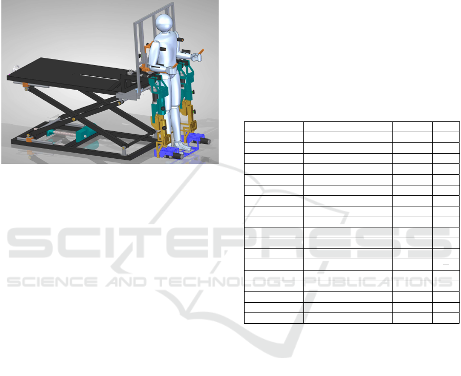
group formed by physiotherapists, industrial design-
ers and engineers. The design consists of two limbs,
each one composed by a three-link mechanism and
an electronic position control. The design also has
brushless motors, power drivers, position and micro
deformation sensors.
Figure 1: Nukawa, the mechatronic rehabilitation device for
lower limb rehabilitation.
The three degrees of freedom (DOF) allows
the system to perform flexion/extension (FE) move-
ments of the hip, FE movements of the knee, and
dorsi/plantar flexion (DP) movements of the ankle
(Pati
˜
no et al., 2013). In addition, the joints are
collinear to human joints. The knee is a polycentric
joint, however this simplification was conducted as
presented by Zoss et. al. (Zoss et al., 2006) who in-
volves a pure rotational joint in the sagittal plane. In
order to adjust the system for each person, the length
of each segment of the mechatronic system Nukawa
is variable, i.e., the length between each joint can be
adjusted. The system is designed for people between
1.44 m and 1.85 m tall, using a telescopic mechanical
system. Therefore, the hip/knee can be adjusted.In
addition, the system was designed for people of no
more than 85 kg weight.
The system dynamics was mathematically mod-
eled using the Newton-Euler method (K. S. Fu, 1987).
The mathematical model of Nukawa includes the
weight and dimensions of both the mechatronic de-
vice and a subject between the ranges previously
stated. For this task, the base of the robot was sup-
posed as fixed to the platform and the element 0 is sta-
tionary, therefore the initial conditions were assumed
as angular speed ω =
˙
ω
0
= 0, the linear speed v
0
= 0,
the center of mass was assumed in the distal point of
each limb, i.e., being this the worst case, and there-
fore obtaining torques greater than the real ones, and
˙v
0
is
˙v
0
=
g
x
g
y
g
z
(1)
The model was implemented in the computational
programming environment Matlab, and right after
that a simplified and graphical model, which includes
the robotic system and the subject, was implemented
in order to test and assess the performance of the
movement of the mechatronic device (Pati
˜
no et al.,
2013) (Kirby, 2016). Table 1 presents the parameters
of the physical model of the robotic system Nukawa,
including the parameters of a subject of 1.85 m height
and 83 kg weight.
Table 1: Nukawa, physical model parameters including a
subject of 1.85 m height and 83 kg weight.
Variable Description Value Unit
kfr1 Friction in hip joint 40 -
kfr2 Friction in knee joint 40 -
kfr3 Friction in ankle joint 40 -
L1 Link 1 length 0.4607 m
L2 Link 2 length 0.4755 m
L3 Link 3 length 0.3278 m
m1p Thigh weight 12.2674 kg
m2p Shank weight 3.9923 kg
m3p Foot weight 1.1371 kg
m1e L1 weight 19 kg
m2e L2 weight 9 kg
m3e L3 weight 11 kg
g Gravity 9.8
m
s
2
Kp Proportional Constant 150 -
Td Derivative Time 0.1 -
m1Saturation Motor 1 saturation 768.458 Nm
m2Saturation Motor 2 saturation 371.377 Nm
m3Saturation Motor 3 saturation 102.689 Nm
Taking into account that m1 = m1p + m1e,
m2 = m2p + m2e, and m3 = m3p + m3e. Also, q1,
q2, and q3 are the angles of the hip, knee and ankle
joint, respectively. The mass matrix was represented
by M(q), the centripetal and coriolis effects were
represented by V (q, ˙q), and the gravitational effects
are represented by G(q).
M(q) =
M
1,1
M
1,2
M
1,3
M
2,1
M
2,2
M
2,3
M
3,1
M
3,2
M
3,3
(2)
M
1,1
= m3 ∗ L3 ∗ (L1 ∗ cos(q2 + q3) + L2 ∗ cos(q3)
+ L3) + m2 ∗ L2 ∗ (L1 ∗ cos(q2) + L2) + m3 ∗ L2
(L1 ∗ cos(q2) + L2 + L3 ∗ cos(q3)) + m1 ∗ L1
2
+ m2 ∗ L1 ∗ (L1 + L2 ∗ cos(q2)) + m3 ∗ L1 ∗ (L1
+ L2 ∗ cos(q2) + L3 ∗ cos(q2 + q3)) (3)
A Hardware-in-the-loop Simulation Study of a Mechatronic System for Anterior Cruciate Ligament Injuries Rehabilitation
71

M
1,2
= m3 ∗ L3 ∗ (L2 ∗ cos(q3) + L3)
+ m2 ∗ L2
2
+ m3 ∗ L2 ∗ (L2
+ L3 ∗ cos(q3)) + m2 ∗ L1 ∗ L2 ∗ cos(q2)
+ m3 ∗ L1 ∗ (L2 ∗ cos(q2) + L3 ∗ cos(q2 + q3))
(4)
M
1,3
= m3 ∗ L3
2
+ m3 ∗ L2 ∗ L3 ∗ cos(q3)
+ m3 ∗ L1 ∗ L3 ∗ cos(q2 + q3) (5)
M
2,1
= m3 ∗ L3 ∗ (L1 ∗ cos(q2 + q3)+
L2 ∗ cos(q3) + L3) + m2 ∗ L2 ∗ (L1 ∗ cos(q2) + L2)
+ m3 ∗ L2 ∗ (L1 ∗ cos(q2) + L2 + L3 ∗ cos(q3))
(6)
M
2,2
= m3 ∗ L3 ∗ (L2 ∗ cos(q3) + L3)
+ m2 ∗ L2
2
+ m3 ∗ L2 ∗ (L2 + L3 ∗ cos(q3)) (7)
M
2,3
= m3 ∗ L3
2
+ m3 ∗ L2 ∗ L3 ∗ cos(q3) (8)
M
3,1
= m3 ∗ L3 ∗ (L1 ∗ cos(q2 + q3)
+ L2 ∗ cos(q3) + L3) (9)
M
3,2
= m3 ∗ L3 ∗ (L2 ∗ cos(q3) + L3) (10)
M
3,3
= m3 ∗ L3
2
(11)
V (q, ˙q) =
V
1,1
V
2,1
V
3,1
(12)
V
1,1
= m3 ∗ L3 ∗ (L1 ∗ sin(q2
+ q3) ∗ q1p
2
+ L2 ∗ sin(q3) ∗ (q1p + q2p)
2
)
+ m2 ∗ L1 ∗ L2 ∗ sin(q2) ∗ q1p
2
+ m3 ∗ L2 ∗ (L1 ∗ sin(q2) ∗ q1p
2
− L3 ∗ sin(q3) ∗ (q1p + q2p + q3p)
2
)
− m2 ∗ L1 ∗ L2 ∗ sin(q2) ∗ (q1p + q2p)
2
− m3 ∗ L1 ∗ L2 ∗ sin(q2) ∗ (q1p + q2p)
2
− L3 ∗ sin(q2 + q3) ∗ (q1p + q2p + q3p)
2
(13)
V
2,1
= m3 ∗ L3 ∗ (L1 ∗ sin(q2
+ q3) ∗ q1p
2
+ L2 ∗ sin(q3) ∗ (q1p + q2p)
2
)
+ m2 ∗ L1 ∗ L2 ∗ sin(q2) ∗ q1p
2
+ m3 ∗ L2 ∗ (L1 ∗ sin(q2) ∗ q1p
2
− L3 ∗ sin(q3) ∗ (q1p + q2p + q3p)
2
) (14)
V
3,1
= m3 ∗ L3 ∗ (L1 ∗ sin(q2
+ q3) ∗ q1p
2
+ L2 ∗ sin(q3) ∗ (q1p + q2p)
2
)
(15)
G(q) = g ∗
G
1,1
G
2,1
G
3,1
(16)
G
1,1
= m3 ∗ L3 ∗ cos(q1 + q2 + q3)
+ m2 ∗ L2 ∗ cos(q1 + q2) + m3 ∗ L2 ∗ cos(q1 + q2)
+ m1 ∗ L1 ∗ cos(q1) + m2 ∗ L1 ∗ cos(q1)
+ m3 ∗ L1 ∗ cos(q1)
(17)
G
2,1
= m3 ∗ L3 ∗ cos(q1 + q2 + q3)
+ m2 ∗ L2 ∗ cos(q1 + q2) + m3 ∗ L2 ∗ cos(q1 + q2)
(18)
G
3,1
= m3 ∗ L3 ∗ cos(q1 + q2 + q3) (19)
The movement control algorithm was imple-
mented using Python in a development platform. This
process was conducted taking into account the math-
ematical model of the robotic system presented in
Equations 2 - 19. The CTC algorithm was used in or-
der to get gravitational compensation and to remove,
or to depreciate, the nonlinearities of the system.
The algorithm was developed to work as a
hardware-in-the-loop (HIL) simulation in order to
test the algorithm without interacting with the actual
robot, but enabling to extract data to assess the algo-
rithm. The implementation was conducted in a de-
velopment platform named Beaglebone Black (BBB)
Rev C, which has AM335x 1GHz ARM
®
Cortex-
8512MB processor and a 512 MB DDR3 Mem-
ory RAM. This implementation was conducted using
Python, the high-level programming language. The
BBB communicates with the mathematical model
placed in a computer, through the TCP/IP protocol
within a predefined communication port in order to
allow remote execution. The sampling period was set
to T S = 0.02 s, therefore the sampling frequency was
f = 50 Hz. The computer used for the test had an
Intel
®
Core™ i5 with a 4 GB DD3 memory RAM.
BIODEVICES 2017 - 10th International Conference on Biomedical Electronics and Devices
72
In order to control the movements of the Nukawa
model, a desired trajectory for each joint must be es-
tablished and then conducted to the CTC algorithm,
e.g., a knee flexion from 0
◦
to 90
◦
in 4 s. Each joint
has a coordinate axis, and a counterclockwise move-
ment is the convention for a positive arc of move-
ment, and the angles are relative to the previous seg-
ment of the robot. The position q = (0
◦
, 0
◦
, 0
◦
)
means that the robot is fully extended, therefore the
three joints should be at 0
◦
, however this position is
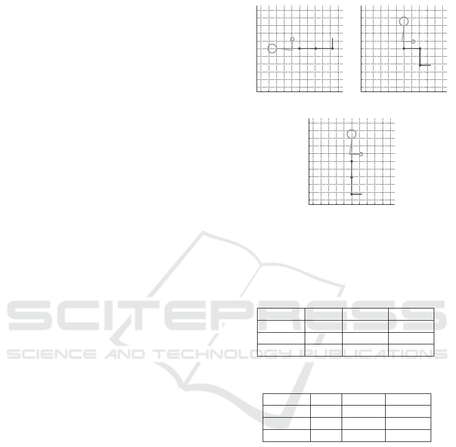
not feasible for the human body. Therefore, the main
positions of the mechatronic system Nukawa are pre-
sented in Figure 2. Figure 2(a) presents the supine
position, i.e., lying horizontally facing up by means
of a q = (0
◦
, 0
◦
, 90
◦
) position, and a backrest an-
gle of 180
◦
. Figure 2(b) presents a sitting position
by means of a q = (0
◦
, −90
◦
, 90
◦
) position, and a
backrest angle of 90
◦
. Finally, Figure 2(c) presents a
standing position by means of a q = (−90
◦
, 0
◦
, 90
◦
)
position, , and a backrest angle of 90
◦
.
The CTC algorithm is responsible for computing
the necessary torque in order to control the movement
of each joint as desired. Thereby, the position of each
limb and joint of the simplified model is modified as
the desired path indicates it. The simulation of the dy-
namics of the system calculated within the computer
in the Matlab is slow compared to T S. Nonetheless,
the control algorithm was designed so that the time
taken by simulation of the dynamics of the model will
not affect the results of the movement, enabling to
control the mechatronic device in Matlab.
2.1 Model Validation
In order to test and assess the dynamics, and the free
motion of the mathematical model, we evaluated the
behavior of the simulator without the controller, i,e,
disabling the torque generated by the CTC, or just en-
abling some parts of it. Five different type of tests
were conducted (A to E), and the mechatronic device
was also initialized at several positions in order to per-
form several sub tests. In total eleven trials were con-
ducted with the purpose of validating the model.
In order to compute the lengths and weights of the
segments regarding a person from 1.44 m to 1.85 m
height and from 50 kg to 100 kg, the models proposed
by Plagenhoef (Plagenhoef et al., 1983) and De Leva
(De Leva, 1996) were used. These models contain
anatomical data for analyzing human motion. Table 2
presents the percentages of total body weight for each
of segments of the lower limb. Table 3 presents the
segment length as a percentage of total height. How-
ever, several models has been proposed in order to
compute body measurements.
−1 −0.8 −0.6 −0.4 −0.2 0 0.2 0.4 0.6 0.8 1
−1
−0.8
−0.6
−0.4
−0.2
0
0.2
0.4
0.6
0.8
1
Sagittal plane (XZ). Schematic of Nukawa Exosqueleton
X Axis (m)
Z Axis (m)
(a)
−1 −0.8 −0.6 −0.4 −0.2 0 0.2 0.4 0.6 0.8 1
−1
−0.8
−0.6
−0.4
−0.2
0
0.2
0.4
0.6
0.8
1
Sagittal plane (XZ). Schematic of Nukawa Exosqueleton
X Axis (m)
Z Axis (m)
(b)
−1 −0.8 −0.6 −0.4 −0.2 0 0.2 0.4 0.6 0.8 1
−1
−0.8
−0.6
−0.4
−0.2
0
0.2
0.4
0.6
0.8
1
Sagittal plane (XZ). Schematic of Nukawa Exosqueleton
X Axis (m)
Z Axis (m)
(c)
Figure 2: Main positions for the mechatronic system,
(a) Supine position q = (0
◦
, 0
◦
, 90
◦
), and a backrest an-
gle of 180
◦
, (b) sitting position q = (0
◦
, −90
◦
, 90
◦
),
and a backrest angle of 90
◦
, and (c) standing position
q = (−90
◦
, 0
◦
, 90
◦
), and a backrest angle of 90
◦
.
Table 2: Percentages of total body weight (De Leva, 1996).
Segment Males Females Average
Thigh 14.16 14.78 14.47
Shank 4.33 4.81 4.57
Foot 1.37 1.29 1.33
Table 3: Segment length as a percentage of total height (Pla-
genhoef et al., 1983).
Segment Men Women Average
Thigh 23.2 24.9 24.05
Shank 24.7 25.7 25.2
Foot 4.25 4.25 4.25
2.2 Test with ACL Rehabilitation
Exercises
In order to assess whether the implemented HIL simu-
lator works properly for ACL rehabilitation exercises,
several tests were conducted. With the assistance of
a physiotherapist with a specialization on Biomedical
Engineering a selection process of the exercises be-
longing to international protocols for rehabilitation of
ACL injuries was performed.
Inclusion criteria were: (a) Exercises that can be
performed with the rehabilitation system Nukawa (b)
Exercises that only involve movements in the sagit-
tal plane (c) Exercises involving only the movement
of a leg (d) Exercises that are repeated at least in two
A Hardware-in-the-loop Simulation Study of a Mechatronic System for Anterior Cruciate Ligament Injuries Rehabilitation
73

phases considering the Accelerated ACL Reconstruc-
tion Rehabilitation Program of Chester, the Classic
1981 Protocol, the Steadman Protocol, and (e) As-
sisted, resisted, and active exercises. Exclusion cri-
teria were: (a) Isometric and isotonic exercises, and
(b) Exercises involving trunk movement.
Subsequently, in order to validate that the robotic
system Nukawa can follow the actual movements per-
formed during the selected exercises, the physiother-
apist performed each of the exercises, and the move-
ments where recorded with a commercial acquisition
device. During each exercise we ordered the expert to
conduct the movements the best way possible, i.e, as
it should be done so that the subject is rehabilitated.
Figure 3 presents the start/end point of the six
exercises. Figure 3(a) and 3(g) presents the start-
ing point and the ending point of an elevation of
straight leg exercise, respectively. Figure 3(b) and
3(h) presents the starting point and the ending point
of an unilateral leg press exercise, respectively. Fig-
ure 3(c) and 3(i) presents the starting point and the
ending point of an assisted extension exercise, respec-
tively. Figure 3(d) and 3(j) presents the starting point
and the ending point of a progressive resisted quadri-
ceps extension exercise, respectively. Figure 3(e) and
3(k) presents the starting point and the ending point
of a progressive resisted hamstring flexion exercise,
respectively. Figure 3(f) and 3(l) presents the starting
point and the ending point of a Displacement of heel
on bed exercise, respectively.
The acquisition device used to capture the move-
ments performed by the expert in physiotherapy was
the wearable body sensing platform BiosignalPlux
powered by Plux®, the sampling rate was f s =
1000 Hz. The sensed data was stored in a text file
using the OpenSignals software, also powered by
Plux®. The BiosignalPlux is a wireless device that
enables to record and to sent real-time information
captured by various sensors that can be connected.
In order to capture the movements performed by the
physiotherapist during the selected exercises, three
twin axis goniometers (SG150) were used. However,
the tests with the HIL simulation only used the flex-
ion/extension channels of each goniometer in order
to measure hip FE movements, knee FE movements,
and ankle DP movements. The goniometers were lo-
cated in the right leg, i.e., the dominant lower limb
member of the physiotherapist. Piriyaprasarth et. al.
(Piriyaprasarth et al., 2008) reported the reliability of
electrogoniometers and stated the importance of us-
ing a standard attachment protocol and standardized
measurement procedures. Therefore, we followed
some of the recommendations of the goniometer and
torsiometer operating manual (Biometrics Ltd, 1998)
from Biometrics Ltd ®.
The physiotherapist wore shorts to allow attach-
ment of the goniometers. These sensors were lo-
cated taking into account that they formed a “simple”
bend, without forming an “Oxbow shape”. The sen-
sors were also located taking into account that the dis-
tance between the two endblocks of the goniometers
were not reduced. Both cares were considered in or-
der to not reduce the accuracy. The endblocks of the
sensors were attached with a double-sided tape, and
they were firmly pressed over the subject.
With the purpose of locating the ankle goniome-
ter, the distal endblock was attached in the back of the
heel of the physiotherapist, without the shoes. Subse-
quently, we asked the physiotherapist to execute the
a dorsiflexion movement, until he reached his maxi-
mum range of motion (ROM). At this point, the prox-
imal endblock was attached at the back of the leg, tak-
ing into account that both axes were coincident.
In order to locate the sensor on the knee joint,
we asked the physiotherapist to stand, so that he was
standing in the neutral position over a flat surface.
The distal endblock was laterally located on the leg,
so the axes of the leg and the endblock were coin-
cident. Then, the goniometer was extended until it
reached the maximum secure position recommended
for the SG150 goniometers, this distance was mea-
sured with a vernier in order to ensure the distance
between the to endblocks as suggested by the oper-
ating manual of the goniometers. Finally, with the
goniometer extended, the proximal endblock was at-
tached to the thigh, tanking into account that both
axes were coincident.
In order to locate the sensor of the hip joint, we
also asked the physiotherapist to stand on a flat sur-
face. The proximal endblock was attached to the
trunk, in the pelvic region. Subsequently, the go-
niometer was also extended until it reached its maxi-
mum recommended by the operating manual, this dis-
tance was also measured using a Vernier. The distal
endblock was attached to the thigh, taking into ac-
count that the axis of the endblock and the axis of the
thigh were coincident when observed in sagittal plane.
With all three goniometers attached to the joints
of the physiotherapist (A), a calibration process was
conducted with the help of another physiotherapist
(B) and the BiosignalPlux. To do so, we asked the
physiotherapist (A) to move each joint separately un-
til he reached the maximum ROM of the joint. At this
point, the physiotherapist (B) measured the angle with
an analog goniometer, and we stored the exact value
with a pushbutton in order to do a manual event anno-
tation of the events. Both data were used to calibrate
the angles of hip, knee, and ankle joints. The trajec-
BIODEVICES 2017 - 10th International Conference on Biomedical Electronics and Devices
74
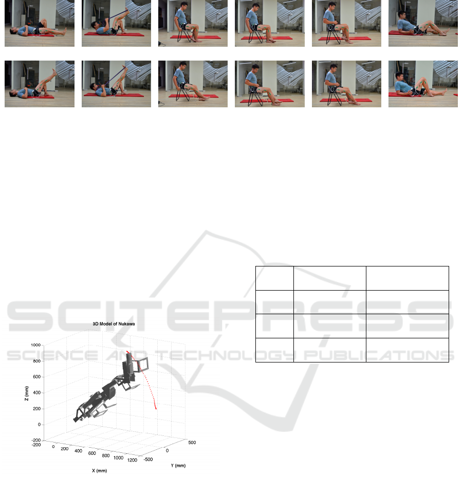
(a) (b) (c) (d) (e) (f)
(g) (h) (i) (j) (k) (l)
Figure 3: Start/end point of the six exercises.
tories or movements executed by the physiotherapist
during the tests with the acquisition device, were fil-
tered using a fifth-order Butterworth Low-pass filter
with a cut-off frequency of 6Hz in order to soften the
signal.
Subsequently, the pre-recorded angles of each
joint were conducted to an offline simulator in or-
der to validate the trajectories of the simulation that
would be used with the HIL simulation. Figure 4
presents one of the six cases, which is the simulation
of an elevation of straight leg exercise. This offline
simulation was conducted using a 3D CAD model of
Nukawa. This simulation included the kinematics of
the robot.
Figure 4: 3D Simulation with pre-recorded trajectories
in order to validate the movements in the right limb of
Nukawa.
Finally, the trajectories were conducted to the HIL
simulation. These movements were a position refer-
ence, i.e., the angles of the hip, knee, and ankle were
conducted as a position references for the three joints
of the robotic system. These movements associated
with therapies for ACL injuries were also used in or-
der to test and assess the movement control algorithm
for mechatronic-assisted rehabilitation. The Integral
Square Error (ISE) (Augusta, 2013) was calculated
for each sub-test. In addition, we assessed whether
each joint movements were within the range of mo-
tion (ROM) of the three joints of the lower limbs tak-
ing into account the values presented in Table 4. We
also measured the execution time, i.e., the time taken
by the movement control algorithm in order to com-
pute the torque of the three joints within each sam-
pling period.
Table 4: Lower extremity range of motion (Nancy Berry-
man, 2002).
Joint Movement
Range of Motion
(
◦
)
Hip
Flexion 122 ± 12
Extension 22 ± 8
Knee
Flexion 134 ± 9
Extension -1 ± 2
Ankle
Dorsiflexion 12 ± 4
Plantar flexion 54 ± 6
3 EXPERIMENTS AND RESULTS
In this section, we present the results of the experi-
ments described in section 2. In the first group of ex-
periments the mathematical model was conducted to
several tests in order to validate it. The second group
of experiments were carried out using six predefined
position references regarding ACL rehabilitation ex-
ercises, in order to test the behavior of the movement
control algorithm.
3.1 Results of the Model Validation
Table 5 presents the results of the eleven trials dis-
abling some parts of the CTC algorithm. The re-
sponse of the system, and a description is presented
for each case. Each type of test is represented with a
prefix letter; i.e. A, B, C, D, E; and the sub tests, using
different initial positions of the rehabilitation system
for the same test, are represented represented with a
suffix number, i.e. A1, A2, A3. The input reference
A Hardware-in-the-loop Simulation Study of a Mechatronic System for Anterior Cruciate Ligament Injuries Rehabilitation
75

was set to ’HOLD’, by means of a static position. The
difference between the desired and actual trajectories
is evaluated through the ISE normalized and explana-
tions about the behavior of the simulation are stated
in the last column of table.
3.2 Results of the Test with ACL
Rehabilitation Exercises
Table 6 presents the results of the six HIL simulation
tests that we performed with predefined references,
i.e., using the trajectories acquired within the tests
with the physiotherapists. This table shows the re-
sults of computing the ISE Normalized for each joint,
these values represent the integration of the square of
the error over time. It penalizes small errors, nonethe-
less it penalizes large error even more. Therefore, it is
proposed that the CTC algorithm implemented within
the BBB eliminates large errors quickly, but it toler-
ates small errors, which are needed for the PD con-
troller to work.
Table 1 includes the values set to saturate the mo-
tors within the mathematical model. Table 6 shows
that maximum torque exerted by controller for each
joint, does not saturate the supposed motors. There-
fore, the motors must meet this torque requirements,
either by construction, or by means of gears, so
that Nukawa may follow the proposed trajectories.
Moreover, the motors must ensure the speed at those
torques.
Table 6 also presents the maximum and minimum
angle for each joint during all six tests. In this tables
one can notice that the angles executed by the robotic
system Nukawa are within the ROM of the lower limb
of the human body. Therefore, the system is validated
in the case that the CTC controller knows the exact
parameters of the model. On the other hand, it is im-
perative to test the system using the entire range of
lengths an weights available within the design.
Figure 5 contains six subfigures, each subfigure
presents the result of HIL simulation for each of the
exercise. The red and dotted line represents the actual
endpoint of the robot, i.e., the distal point of the third
limb (L3). The blue dotted line represents the desired
position trajectory for the endpoint of the robot. Con-
sequently, it is proposed that the robotic system may
conduct mechatronic-assisted rehabilitation based on
exercises and movements associated with therapies
for ACL injuries.
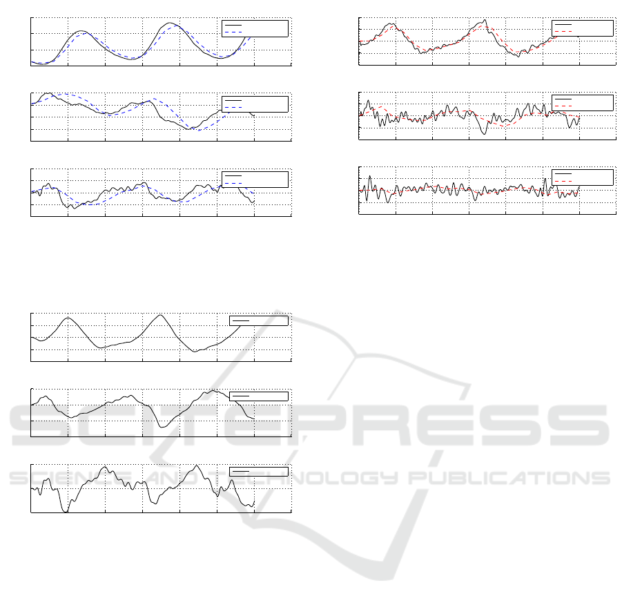
Figures 6, 7, and 8, present the results of the first
exercise. Figure 6 compares the desired position in
a continuous line, and the actual position with a dot-
ted line. In this figure it is possible to observe that the
system is able to follow the desired position reference,
due to the fact that both are almost overlapped, with
a delay. We can denote that the system correctly fol-
lows the imposed reference not only visualizing Fig-
ure 6 but for the error presented in Figure 7. Figure 8
presents the desired speed in continuous line and the
actual speed in dotted line.
Related with times, the mean execution time (M)
and the standard deviation (SD) taken by the con-
troller in each of the tests were computed. The con-
troller does not take more than M = 11.5 ms on aver-
age with a maximum standard deviation of SD = 3.9.
With this, it is proposed that the implementation can
be tested with the real-time system, without any sig-
nificant delays generated by the calculation of the
control action.
4 DISCUSSION
As an analysis of the tests presented in section 2.1,
which involved eleven trials, the model of the rehabil-
itation system has an appropriate behavior, therefore
it was validated. In the tests described in section 2.2,
the results with the six exercises show that the sys-
tem may follow several desired trajectories. The ISE
compared with the references entered in the system
are small, and may be despised. Therefore, it is con-
sidered that the controller is capable of manipulating
the torque of the joints, so that it follows specific tra-
jectories. According to that, the controller is able to
manipulate the three torques at the same time, hence
it is possible to follow specific trajectories. Taking
into account the mean execution time (M) and the
standard deviation (SD) taken by the controller within
the BBB, it is proposed that this system can be tested
in real-time, without notable delays related with the
movement control algorithm.
5 CONCLUSION AND FUTURE
WORK
The tests of the model showed that when the CTC al-
gorithm is deactivated, a three-segment pendulum be-
havior is obtained, as expected in an RRR robot with
no torque in the motors.
Additionaly, we observed that only with the grav-
itational compensation component of the CTC algo-
rithm, the controller is able to keep the robot in a static
position reference, i.e., the initial position.
These simulations have shown the feasiblility of
implementing a HIL simulation in order to control the
movements of a simplified model of Nukawa. How-
BIODEVICES 2017 - 10th International Conference on Biomedical Electronics and Devices
76

Table 5: Model validation trials.
Trial Tu
Initial
Position
(
◦
,
◦
,
◦
)
Backrest
Position
(
◦
)
Reference
ISE Normalized
Description
A1 Tu (0,0,90) 180 Hold (5.0e-07, 1.5e-06, 2.5e-08)
No movement was observed,
the motors were not saturated.
The ISE error may be despised
A2 Tu (-90,0,90) 90 Hold (3.1e-08, 2.0e-09, 3.8e-08)
No movement was observed,
the motors were not saturated.
The ISE error may be despised
A3 Tu (0,-90,90) 90 Hold (1.5e-07, 1.4e-08, 5.7e-08)
No movement was observed,
the motors were not saturated.
The ISE error may be despised
B1 0 (0,0,90) 180 Hold (8.683e+03, 361.3, 2.809e+03)
The robot fell as a pendulum with
a big oscillation of the hip joint,
the motors did not perform any torque.
The ISE error shows that
the system failed to hold the position
B2 0 (-90,0,90) 90 Hold (7.3, 103.4, 2.004e+03)
The robot dropped as a pendulum with
a small oscillation of the hip joint,
the motors did not perform any torque.
The ISE error shows that
the system failed to hold the position with
a big movement of the ankle joint
B3 0 (0,-90,90) 90 Hold (7.206e+03, 5.162e+03, 3.577e+03)
The robot dropped as a pendulum with
a big oscillation of the hip, knee and ankle joint,
the motors did not perform any torque.
The ISE error shows that
the system failed to hold the position
C1 Gc (0, 0, 90) 90 Hold (2.0e-04, 1.4e-05, 4.5e-08)
The robot stayed at the initial position,
and no saturation occurred.
The ISE error may be despised
C2 Gc (-90,0,90) 90 Hold (4.3e-08, 1.3e-17, 4.3e-08)
The robot stayed at the initial position,
and no saturation occurred.
The ISE error may be despised
C3 Gc (-90,0,90) 90 Hold ( 3.0e-04, 2.8e-08, 4.9e-08)
The robot stayed at the initial position,
and no saturation occurred.
The ISE error may be despised
D Vc (0,0,90) 90 Hold ( 7.7e+03, 454.1, 1.488e+03)
The robot dropped as a pendulum with
a big oscillation of the hip, knee and ankle joint,
the motors did not perform any torque.
The ISE error shows that
the system failed to hold the position
E Mc (0,0,90) 90 Hold (8.464e+03, 454.154, 1.488e+03)
The robot dropped as a pendulum with
a big oscillation of the hip, knee and ankle joint.
The ISE error shows that
the system failed to hold the position
ever, the computational model may differ from the
physical, due to the fact of simplifications or inaccu-
racies. Therefore, a future work requires to conduct
these tests with the actual robotic system.
The use of the development platform Beablebone
Black Rev C (BBB) proved to be useful for the im-
plementation of the CTC control since the response
time is in an acceptable range, i.e., it is lower than the
sampling period. In addition, the performance of the
control algorithm implemented in Beagle Bone Black
Rev C (BBB) may be evaluated in other development
platforms such as the new Raspberry Pi 3, and others.
The Hardware-In-The-Loop (HIL) simulation of
the mathematical model with the dynamics of the
Nukawa rehabilitation system allowed to validate the
CTC control algorithm without the need to have the
actual robot and thus to make variations in the control
parameters and to evaluate the system response.
In order to obtain a model closer to the real one,
before testing the controller, it is imperative to config-
ure the system with known lengths and weights, and
to drop it from the Position q = (0
◦
, 0
◦
, 90
◦
), with-
out restrictions or mechanical limits enabled. During
this test the position of each joint must be acquired
and then, an optimization algorithm must be used in
order to tune the friction coefficients. Preliminary
tests, show that the value of the dynamic friction in-
fluences in the behavior of the system, e.g., when the
constant k f r = 0, the system behaves like a system
without friction and stays oscillating without losing
A Hardware-in-the-loop Simulation Study of a Mechatronic System for Anterior Cruciate Ligament Injuries Rehabilitation
77
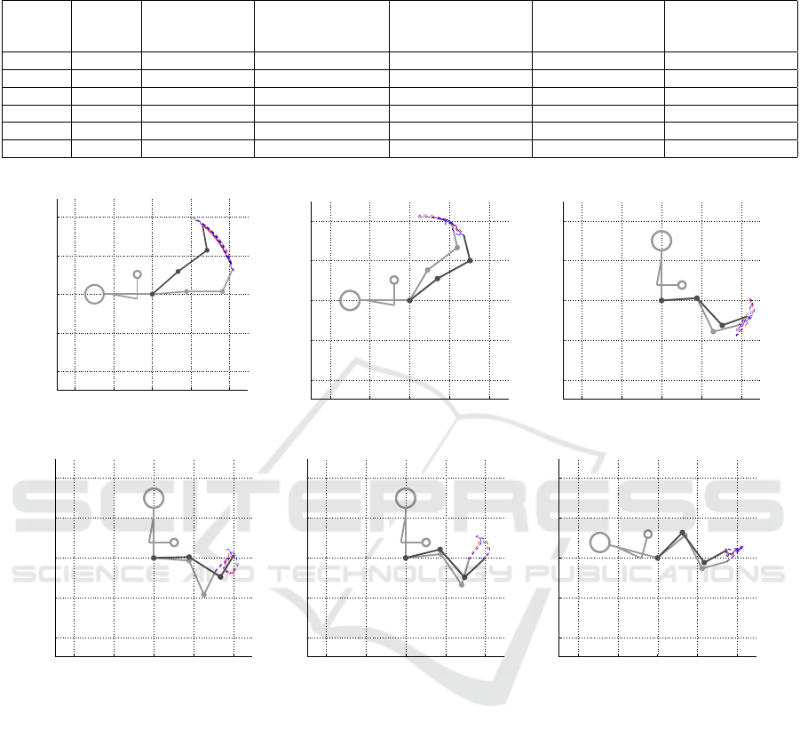
Table 6: Results of the six HIL simulations using predefined trajectories extracted from ACL rehabilitation exercises executed
by a physiotherapist and acquired with three twin-axis goniometers.
Exercise
Backrest
Angle
(
◦
)
ISE
Normalized
Maximum
Torque
(Nm, Nm, Nm)
Minimum
Torque
(Nm, Nm, Nm)
Maximum
Angle
(
◦
,
◦
,
◦
)
Minimum
Angle
(
◦
,
◦
,
◦
)
1 180 (19.6, 8.5, 5.2) (727.6, 278.6, 64.4) (-113.8, -85.1, -51.5) ( 50.1, -0.3, 68.7) (2.8, -15.6, 59.4)
2 180 (41.6, 92.3, 7.9) (424.7, 181.0, 19.9) (-131.9, -1.1, -37.0) (101.0, -8.8, 81.0) (38.0, -57.2, 65.1)
3 90 (2.7, 30.3, 31.4) (491.4, 207.1, 71.8) (211.4, 20.6, -10.0) (5.0, -17.9, 78.3) (-5.1, -70.7, 52.7)
4 90 (2.2, 25.8, 42.1) (453.3, 170.2, 74.6) (212.3, 55.9, -34.1) (4.1, -29.9, 130.0) (-4.4, -63.8, 82.7)
5 90 (2.3, 24.2, 33.1) (433.5, 142.1, 69.8) (259.7, 62.9, -40.3) (13.9, -29.9, 130.0) (6.2, -62.6, 82.7)
6 165 (5.7, 37.4, 21.2) (477.2, 176.4, 75.4) (153.1, 15.2, 2.4) (46.5, -57.7, 83.3) (24.9, -101.8, 69.6)
−1 −0.5 0 0.5 1
−1
−0.5
0
0.5
1
Sagittal plane (XZ). Schematic of Nukawa Exosqueleton
X Axis (m)
Z Axis (m)
(a)
−1 −0.5 0 0.5 1
−1
−0.5
0
0.5
1
Sagittal plane (XZ). Schematic of Nukawa Exosqueleton
X Axis (m)
Z Axis (m)
(b)
−1 −0.5 0 0.5 1
−1
−0.5
0
0.5
1
Sagittal plane (XZ). Schematic of Nukawa Exosqueleton
X Axis (m)
Z Axis (m)
(c)
−1 −0.5 0 0.5 1
−1
−0.5
0
0.5
1
Sagittal plane (XZ). Schematic of Nukawa Exosqueleton
X Axis (m)
Z Axis (m)
(d)
−1 −0.5 0 0.5 1
−1
−0.5
0
0.5
1
Sagittal plane (XZ). Schematic of Nukawa Exosqueleton
X Axis (m)
Z Axis (m)
(e)
−1 −0.5 0 0.5 1
−1
−0.5
0
0.5
1
Sagittal plane (XZ). Schematic of Nukawa Exosqueleton
X Axis (m)
Z Axis (m)
(f)
Figure 5: HIL Simulation of the Nukawa using a trajectory extracted during the six exercises.
energy. On the other hand, when k f r increases the
system oscillates fewer times.
It is considered as future work the inclusion of the
static friction in the mathematical model of the robot,
which would allow to take into account the force that
is opposed to the beginning of the movement, i.e., in-
cluding the static friction would include the effects
that may generate a dead zone for the controller. Even
though a slightly larger torque is exerted, no move-
ment will be generated until it is able to overcome
static friction. In addition, it is possible to include the
friction that occurs between the robot and the patient
with the air.
Some of the perturbations of the system may be
known a priori, therefore, it is proposed that in the fu-
ture they may be included in the CTC algorithm, in
order to make a feedforward control, e.g., using an
estimate of the dynamic and static friction in the al-
gorithm of CTC, in order to compensate the perturba-
tions that the system can suffer due to these and thus,
not leave all the work to the external loop controller,
facilitating the work.
Another future work is to use the 3D model of
Nukawa or even to do experimental tests with the
actual robot, to calculate the center of mass of each
limb, as well as to use the models proposed by De
Leva, in order to obtain a mathematical model closer
to the real one.
In the future, HIL simulation tests can be per-
formed using speed, acceleration or force references
rather than position references. These test may be
conducted in order to control the torque of the motors
BIODEVICES 2017 - 10th International Conference on Biomedical Electronics and Devices
78
0 1 2 3 4 5 6 7
0
20
40
60
Hip
Angle (
°
)
Desired position
Actual position
0 1 2 3 4 5 6 7
−20
−15
−10
−5
0
Knee
Angle (
°
)
Desired position
Actual position
0 1 2 3 4 5 6 7
55
60
65
70
75
Ankle
Time (s)
Angle (
°
)
Desired position
Actual position
Figure 6: Desired position vs actual position of each joint
of the Nukawa during a HIL Simulation using a trajectory
extracted during an elevation of straight leg exercise.
0 1 2 3 4 5 6 7
−10
−5
0
5
10
Hip
Angle (
°
)
Position error
0 1 2 3 4 5 6 7
−10
−5
0
5
Knee
Angle (
°
)
Position error
0 1 2 3 4 5 6 7
−5
0
5
Ankle
Time (s)
Angle (
°
)
Position error
Figure 7: Position error of each joint of the Nukawa dur-
ing a HIL Simulation using a trajectory extracted during an
elevation of straight leg exercise.
to perform other type of exercises rather than isoki-
netic, e.g., Isotonic.
Further work, also includes implementing the con-
trol algorithm in the Robot Operating System (ROS),
and implementing the simulations in an environment
other than Matlab such as Gazebo, V-REP, Peekabot,
Webots, Drake, among others.
Finally, the system was able to reproduce the tra-
jectories associated with the phases 2 and 4 consid-
ering The Accelerated Reconstruction Rehabilitation
Program of Chester, phase 1 and 2 of the Classic 1981
Protocol and pre-operatory and post-operatory phase
in Steadman Protocol of Anterior Cruciate Ligament
(ACL) rehabilitation protocols. This will allow to val-
idate in the future different types of exercises that
include these trajectories, i.e., isotonic, assisted, re-
sisted, among others.
0 1 2 3 4 5 6 7
−100
−50
0
50
100
Hip
Angle (
°
/s)
Desired speed
Actual speed
0 1 2 3 4 5 6 7
−40
−20
0
20
40
Knee
Angle (
°
/s)
Desired speed
Actual speed
0 1 2 3 4 5 6 7
−100
−50
0
50
100
Ankle
Time (s)
Angle (
°
/s)
Desired speed
Actual speed
Figure 8: Desired speed vs actual speed of each joint of
the Nukawa during a HIL Simulation using a trajectory ex-
tracted during an elevation of straight leg exercise.
The constants of the outer loop were set using an
heuristic PD tuning method, these methods and values
were appropriate for the current application. How-
ever, it could be a better approach if an optimization
method is used, i.e., an autotuning method.
Further work, also includes acquiring the same
trajectories during the six exercises with a group of
subjects, moreover, with patients in order to compare
the trajectory execute by both, healthy and unhealthy
subjects and to propose trajectories that fit all sub-
jects.
ACKNOWLEDGEMENTS
The authors would like to express their sense of grat-
itude to the engineer Juan G. Pati
˜
no and the magister
Florian Kirby for their help modelling the robotic sys-
tem, and conducting the offline simulations. We thank
“IPS ARTHROS” and the “Centro de MVMT”, for
providing the facilities for the tests. We also thank the
physiotherapy student Lina loaiza, and intern in “IPS
ARTHROS” for her help with the execution of the
tests. We thank the electronic engineer Mario Portela
and the mechanical engineer Juan Guillermo Madrid,
for their support during the acquisition of technical
information of the robotic system Nukawa. Finally,
we sincerely thank the “Departamento Administrativo
de Ciencia, Tecnolog
´
ıa e Innovaci
´
on (Colciencias)”
for their grant within the project called “MyoLegSys”
with agreement 836-2015.
A Hardware-in-the-loop Simulation Study of a Mechatronic System for Anterior Cruciate Ligament Injuries Rehabilitation
79

REFERENCES
Akdogan, E. and Adli, M. A. (2011). The design and control
of a therapeutic exercise robot for lower limb rehabili-
tation: Physiotherabot. Mechatronics, 21(3):509–522.
American Academy of Orthopaedic Surgeons (2011).
Sports Medicine Media Guide an Illustrated Resource
on the Most Common Injuries and Treatments in
Sports.
Arosha Senanayake, S. M. N., Malik, O. A., Iskandar, P. M.,
and Zaheer, D. (2014). A knowledge-based intelli-
gent framework for anterior cruciate ligament rehabil-
itation monitoring. Applied Soft Computing Journal,
20:127–141.
Augusta, V. (2013). Comparaci
´
on entre diferentes proced-
imientos de ajuste de controladores PID. I. Valores
m
´
aximos de la variable controlada y de la se
˜
nal regu-
ladora.
Biometrics Ltd (1998). Goniometer and torsiometer oper-
ating manual. Technical report.
Blaya, J. a. and Herr, H. (2004). Adaptive Control of
a Variable-Impedance Ankle-Foot Orthosis to Assist
Drop-Foot Gait. IEEE Transactions on Neural Sys-
tems and Rehabilitation Engineering, 12(1):24–31.
Cimino, F., Volk, B. S., and Setter, D. (2010). Anterior
cruciate ligament injury: Diagnosis, management, and
prevention. American Family Physician, 82(8):917–
922.
De Leva, P. (1996). Adjustments to zatsiorsky-seluyanov’s
segment inertia parameters. Journal of Biomechanics,
29(9):1223–1230.
Departamento Administrativo Nacional de Estad
´
ısctica
(2004). Informaci
´
on estad
´
ıstica de la discapacidad.
Dollar, A. M. and Herr, H. (2008). Lower extremity
exoskeletons and active orthoses: Challenges and
state-of-the-art. IEEE Transactions on Robotics,
24(1):144–158.
Eby, W. R. (2005). Feasibility Analysis of a Powered
Lower-Limb Orthotic for the Mobility Impaired User
by. Simulation.
Eurostat (2014). Disability statistics - prevalence and de-
mographics. 2011(September):1–5.
Ganley, T. J. (2011). Preface: ACL Injuries in the Young
Athlete: A Focus on Prevention and Treatment. Clin-
ics in Sports Medicine, 30(4):xv–xviii.
Guizzo, E. and Goldstein, H. (2005). The rise of the
body bots [robotic exoskeletons. IEEE Spectrum,
42(10):50–56.
K. S. Fu, R.C. Gonzalez, C. L. (1987). Robotics: Control,
Sensing, Vision, and Intelligence. Mcgraw-Hill Book
Company.
Kiguchi, K., Tanaka, T., and Fukuda, T. (2004). Neuro-
fuzzy control of a robotic exoskeleton with EMG
signals. IEEE Transactions on Fuzzy Systems,
12(4):481–490.
Kirby, F. (2016). Simulaci
´
on de los algoritmos de control
de un sistema de rehabilitaci
´
on de miembro inferior
(LegSys). Master’s thesis, Universidad Pontificia Bo-
livariana.
Lasso, I. L., Masso, M., and Vivas, O. A. (2010). Ex-
oesqueleto para reeducaci
´
on muscular en pacientes
con IMOC tipo diplej
´
ıa esp
´
astica moderada. pages
1 – 88.
Li, A. Y. and Ng, G. Y. (2004). Overview of Anterior Cruci-
ate Ligament Rehabilitation and its Evolution in Hong
Kong in the Past 8 Years. Hong Kong Physiotherapy
Journal, 22(1):14–21.
Machhindra, V., Lal, H., Chowdhury, B., Dev, C., Meena,
S., and Kumar, K. (2016). ScienceDirect Arthroscopic
anatomic double bundle anterior cruciate ligament re-
construction : Our experience with follow-up of 4
years. 7:3–8.
Nancy Berryman, W. D. B. P. (2002). Joint Range of Motion
and Muscle Length Testing. 1st edition.
Nguyen-Tuong, D. and Peters, J. (2008). Learning robot dy-
namics for computed torque control using local Gaus-
sian processes regression. Proceedings of the 2008
ECSIS Symposium on Learning and Adaptive Behav-
iors for Robotic Systems, LAB-RS 2008, pages 59–64.
Olaya, A. R. (2008). Sistema rob
´
otico multimodal para
an
´
alisis y estudios en biomec
´
anica, movimiento hu-
mano y control neuromotor. pages 1–256.
Pan, D., Gao, F., Miao, Y., and Cao, R. (2015). Co-
simulation research of a novel exoskeleton-human
robot system on humanoid gaits with fuzzy-PID/PID
algorithms. Advances in Engineering Software,
79:36–46.
Pati
˜
no, J. G., Bravo, E. E., Perez, J. J., and Perez, V.
(2013). Lower limb rehabilitation system controlled
by robotics, electromyography surface and functional
electrical stimulation. Pan American Health Care Ex-
changes, PAHCE, (2002):6257.
Piriyaprasarth, P., Morris, M. E., Winter, A., and Bialo-
cerkowski, A. E. (2008). The reliability of knee joint
position testing using electrogoniometry. BMC mus-
culoskeletal disorders, 9:6.
Plagenhoef, S., Evans, F. G., and Abdelnour, T. (1983).
Anatomical Data for Analyzing Human Motion. Re-
search Quarterly for Exercise and Sport, 54(2):169–
178.
Pratt, J., Krupp, B., Morse, C., and Collins, S. (2004). The
RoboKnee: an exoskeleton for enhancing strength and
endurance during walking. IEEE International Con-
ference on Robotics and Automation, 2004. Proceed-
ings. ICRA ’04. 2004, 3(April):2430–2435.
World Health Organization (2011). World Report on Dis-
ability. Technical report, World Health Organization,
Ginebra.
Yan, T., Cempini, M., Oddo, C. M., and Vitiello, N. (2015).
Review of assistive strategies in powered lower-limb
orthoses and exoskeletons. Robotics and Autonomous
Systems, 64:120–136.
Zoss, A. B., Kazerooni, H., and Chu, A. (2006). Biome-
chanical Design of the Berkeley Lower Extremity Ex-
oskeletong (BLEEX). IEEE/ASME Transactions on
Mechatronics, 11(2):128–138.
BIODEVICES 2017 - 10th International Conference on Biomedical Electronics and Devices
80
