
Digital Mirror Devices for Mode Selective Excitation in Multimode
Fibers
Andreas Ahrens, Steffen Lochmann and Peter Bartmann
Hochschule Wismar, University of Technology, Business and Design, Philipp-Müller-Straße 14, 23966 Wismar, Germany
Keywords:
Optical MIMO, Space Division Multiplexing, Digital Mirror Devices (DMDs), Digital Light Processor
(DLP), Mode Combining.
Abstract:
Space division multiplex (SDM) in optical communications became an attractive research topic in recent years.
A tremendous increase of data rates was exposed. In optical multiple-input multiple-output (OMIMO) SDM
can be achieved by using separated fiber cores or several modes in multimode fibers (MMF). This paper tackles
the task of mode selective excitation in MMFs. A completely new approach is shown utilizing digital mirror
devices (DMDs) in this field. However, finding the optimal coupling conditions is a complex task due to the
blazed grated structure of the micromirror array (MMA). A possible and intuitive solution for that problem is
shown. Still, the benefits of such DMDs lies in the flexibility of mode excitation and the low insertion loss of
around ´1.27dB. This paper shows that the mode separation is comparative to mode excitation achieved with
offset splices.
1 INTRODUCTION
Time division, wavelength and polarization multi-
plexing as well as high order modulation schemes
have been developed coping with the exponential
grow of data traffic in optical networks and have
reached a state of maturity. Therefore, there exists
an increasing interest in optical space division multi-
plexing (SDM). Adapting well-known wireless com-
munications multiple-input multiple-output (MIMO)
techniques to optical multiple-input multiple-output
(OMIMO) transmission has been discussed in sev-
eral papers like (Hsu et al., 2004; Hsu et al., 2006).
In analogy to wireless communications, where spa-
tial diversity gained by separated antennas is suffi-
cient for a MIMO channel, OMIMO exploits mode
diversity in multimode fibers (MMFs) among others.
However, the first experiment for modal multiplex-
ing dates back to 1982, where it was demonstrated
in a 10-m long MMF (Berdagué and Facq, 1982).
Newer publications show the feasibility of 2 ˆ 2 up
to 12 ˆ 12 OMIMO systems in longer optical links of
km-domain (Shah et al., 2005; Ryf et al., 2012). How-
ever, efficient excitation of specific modes in a MMF
and their respective coupling and splitting is an open
question.
This paper tackles the problem of mode selective
excitation into conventional MMFs. Conventional ap-
proaches use centric and eccentric splices of a sin-
glemode fiber (SMF) to a MMF (Schollmann et al.,
2008). Due to the offset launching condition different
modegroups are excited within the MMF depending
on the eccentricity of the splice. Afterwards two or
more modegroups in different MMFs are combined
using fusion couplers. The hard reproducibility as
well as the low flexibility are two drawbacks of this
method. Another approach is to utilize spatial light
modulators (SLMs). With SLMs as described in (Gu
et al., 2013), for instance, individual modes can be
excited with high contrast. Nevertheless, the atten-
uation due to the serial mode combining with semi-
permeable mirror couplers, which has to be used for a
concatenation of SLMs, leads to an exponential grow-
ing power loss of 3dB in each step.
Addressing these problems this paper shows a new
approach utilizing Digital Light Processor
®
(DLP)
chips as coupling devices. The use of digital mirror
devices (DMDs) in optical networks is described for
one source in (Yoder et al., 2001), where the DMD
has been used as a signal level controlling or network
switching device. However, this paper extends its us-
ability for SDM. The micromirror array (MMA) of
a DMD has to be considered as a diffraction grating
with blazed condition. Hence, the reflection of an in-
citing laser beam produces multiple diffraction maxi-
mums. Finding the global maximum in a mechanical
Ahrens, A., Lochmann, S. and Bartmann, P.
Digital Mirror Devices for Mode Selective Excitation in Multimode Fibers.
DOI: 10.5220/0005948500190024
In Proceedings of the 13th International Joint Conference on e-Business and Telecommunications (ICETE 2016) - Volume 3: OPTICS, pages 19-24
ISBN: 978-989-758-196-0
Copyright
c
2016 by SCITEPRESS – Science and Technology Publications, Lda. All rights reserved
19
setup becomes a complex task. To avoid possible side
effects of this in the OMIMO field new technology
this paper concentrates on 2 ˆ 2 OMIMO. This con-
tribution is structured as follows: Sec. II starts with
a short description of the coupling system. More in
detail Sec. III defines parameters as well as the coor-
dinate systems used to determine the diffraction be-
haviour of the DLP in Sec. IV. The mathematical de-
scription is then used in Sec. V finding optimal cou-
pling conditions for the experimental setup. Sec. VI
shows how the theory is realized and the first results
achieved with visible light. They are compared to pre-
vious results from (Sandmann et al., 2014). The paper
closes with a conclusion-section in VII.
2 UTILIZING DMDS IN OPTICAL
MIMO
The breakthrough of the DLP technology can be
traced back to efforts made by Texas Instruments (TI)
at the beginning of the eighties, more precisely to
Larry J. Hornbeck. The heart of a DLP projector is
the DMD, which is patented by TI in 1986. The DMD
consists of thousand of small mirrors having sizes in
micrometer domain. The micromirrors are synony-
mously referred as pixels. The principle of a DMD
is quite simple: each mirror can be tilted such that a
light source is reflected to either an optical output sys-
tem or an absorber. Hence, each pixel can be switched
into so called ’on’- and ’off’-states. This principle is
adapted for OMIMO as depicted in Fig. 1.
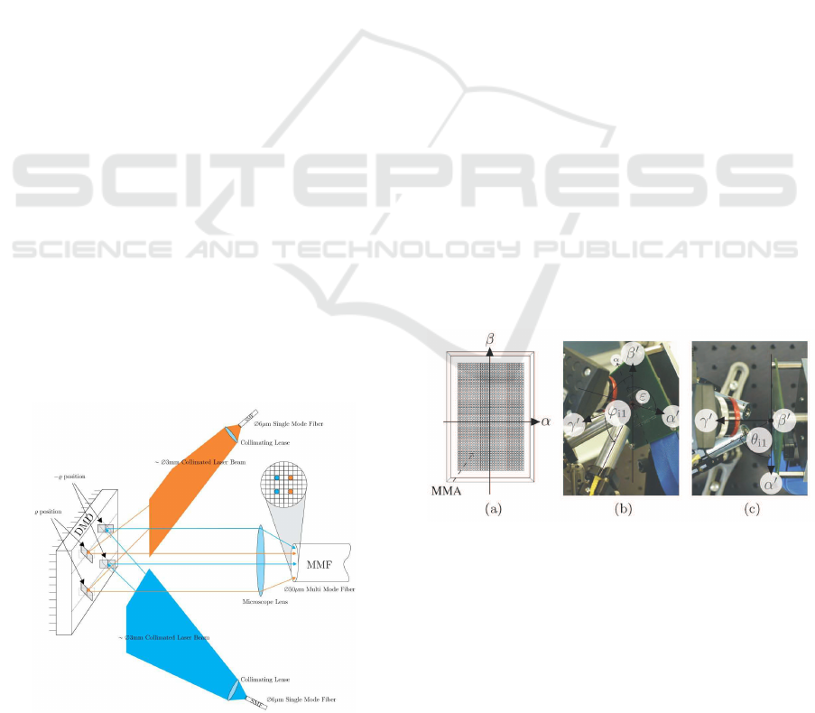
Fig. 1 shows the principle for the coupling pro-
cess. Utilizing the property that each single mirror
can be addressed to two opposite states, two inde-
pendent sources can be arranged in front of the DLP
Figure 1: DMD supported optical space division multiplex-
ing.
such that the main output direction of both reflected
laser beam patterns is equal for both sources. The
light sources are simply two SMF at which ends are
collimating lenses to widen the light into collimated
laser beams. These beams are reflected by the MMA
where mirrors in ’on’-state reflect only one source to
the output direction, for the other source mirrors in
’off’-state do. In this output direction an optic focuses
the reflected laser beams onto a MMF. Thus, the tilt
pattern on the MMA performs SDM. A flexible so-
lution for a parallel excitation of low and high order
modes can be designed.
3 DEFINITIONS
This section defines in a first step two different coor-
dinate systems: one aligned with the DLP, the other
one with the setup as well as their mathematical con-
nectedness. In a second step the coupling parameters
are defined in the second space.
The whole mathematical description is made in
the direction cosine space (DCS) (Tang, 2007) whose
axes are orientated with the micromirror vertices. Fig.
2 illustrates its orientation. The origin lies in the
MMAs center. The tilt axes of each micromirror is
parallel to α “ ´β. This means in other words that
the normal of each mirror lies parallel to the plane
spanned by the γ-axis and the line α “ β. In the ’on’-
or ’off’-state of a pixel the angle between the normal
of the mirror and the γ-axis is either `ρ or ´ρ, re-
spectively.
Figure 2: Experimental setup and its coordinates of the di-
rection cosine space.
The second DCS is motivated by the aim that the
experimental setup is symmetric related to the vertical
plane on an optical breadboard. Considering that it is
defined as depicted in Fig. 2 b) and 2 c). The DMD is
rotated in the α
1
β
1
-plane by ε such each normal of a
micromirror is parallel to the α
1
γ
1
-plane independent
on the state of the mirror. Hence, mirrors in ’on’-state
can be used by one source, mirrors in ’off’-state by
OPTICS 2016 - International Conference on Optical Communication Systems
20

the other source. The two DCSs are connected by
ˆ
α
1
β
1
˙
“ R
ˆ
α
β
˙
(1)
and
γ
1
“ γ , (2)
where R is a simple two dimensional rotation matrix.
There are two coupling parameters for each direc-
tion defined, where Fig. 2 exemplary shows them for
the first input direction. The angle between the pro-
jection of the location vector of a source onto the α
1
γ
1
-
plane and the γ
1
-axis is called θ and the angle between
the location vector and the β
1
-axis is ϕ. The two an-
gles are orthogonal to each other. Subscripts like i1,
i2 and o denotes the connection of an parameter to
the first or second input or the output direction. By
applying simple vector calculation as well as the con-
nection between a Cartesian space and the DCS one
can easily derive the association between coupling pa-
rameters and the DCS.
α
1
“ cospθqsinpϕq (3)
β
1
“ cospϕq (4)
4 DIFFRACTION BEHAVIOUR OF
THE MMA
Due to the physical structure of the MMA, the DMD
has to be considered as a two dimensional blazed grat-
ing. If the mirrors are not tilted, the MMA reacts as
a common diffraction grating with the difference that
the light is reflected instead of passing a two dimen-
sional lattice. In the case of one dimension the macro-
scopic equation of diffraction is given by
sinξ
i
˘ sin ξ
o
“ m
λ
g
, (5)
where ξ
i
is the incident angle, ξ
o
the output an-
gle, λ the used wavelength and g the grating con-
stant (Goodman, 2005). Note that the angles ξ are
measured to the array normal, which is different to
the definition of θ. The variable m gives the order
of the grating which is an integer limited by physical
possible directions. In the setup corresponding angles
of zeroth order are given by
θ
o
“ π ´ θ
i
(6)
and
ϕ
o
“ π ´ ϕ
i
. (7)
In (Harvey and Vernold, 1998) the derivation of (5) to
the appropriate DCS representation is presented. By
extending these equations to the two dimensional case
the grating behaviour can be described by
α
o
` α
i
“
ˆ
m
λ
g
˙
(8)
and
β
o
` β
i
“
ˆ
n
λ
g
˙
. (9)
The transition from the macroscopic equation to
the real intensity distribution of the reflected light has
to be taken in order to find optimal coupling param-
eters. By neglecting the faceted profile of the MMA
(Hayat, ), i.e., the blazed structure, and by utilizing
the same mathematical tools as in (Harvey and Ver-
nold, 1998), the full intensity distribution is defined
by
I
D
pα, βq “ I
0
ˆ
sinpP
α
πpg{λqpα ´α
o
qq
P
α
sinpπpg{λq pα ´ α
o
qq
˙
2
˜
sin
`
P
β
πpg{λqpβ ´β
o
q
˘
P
β
sinpπpg{λq pβ ´ β
o
qq
¸
2
. (10)
The number of micromirrors (pixels) in α- and β-
direction is denoted by P
α
and P
β
. Under the con-
dition that (8) and (9) hold, (10) becomes the normal-
ization constant I
0
which is a multiple occurred global
maximum.
By considering the profile of the MMA one takes
the step into the blazed grated structure. Due to the
symmetric setup the blazed behaviour influences the
output parameter θ
o
whereas the ϕ
o
stays unchanged
compared to (7). Due to the tilt of the mirror ρ the
angle θ
o,b
becomes
θ
o,b
“
#
π ´ 2ρ ´θ
i
for ε “ ´π{4
π ` 2ρ ´θ
i
for ε “ `3π{4 ,
(11)
where the subscript o,b denotes the blazed output di-
rection. From (Instruments, 2008) it is known that
the faceted profile creates a sinc
2
p¨q-envelope on the
intensity distribution (10) in each direction. By con-
sidering the rotation (1) and applying (3) to (11) to get
the blazed parameters α
o,b
and β
o,b
one ends up with
Ipα, βq “I
D
pα, βq sinc
2
´
s
λ
p
α ´ α
o,b
q
¯
sinc
2
´
s
λ
pβ ´ β
o,b
q
¯
,
(12)
being the complete description of the intensity distri-
bution of the MMA reflected laser beam, where s is
the length of an edge of a micromirror.
Digital Mirror Devices for Mode Selective Excitation in Multimode Fibers
21
5 OPTIMAL CONDITIONS FOR
OPTICAL MIMO COUPLING
Using this equation one can define an optimization
program whose result gives the coupling parameters
one has to apply in the experimental setup. A simpli-
fied program is evaluated as follows:
pθ
i1
, ϕ
i1
q “ argmax
0ăθ
i1
ăπ{2
pi{2ăϕ
i1
ăπ
max
α“0
β
ρ“`π{15
ε“´π{4
Ipα, βq . (13)
This program considers the symmetric setup achieved
by the DMD rotation by ε. The optimization returns
the coupling parameters of the first source i1. Note
that α “ 0 assumes θ
o
“ π. The missing parameters
of the second source i2 as well as for the output o are
defined by the symmetry.
θ
i2
“ π ´ θ
i1
(14)
ϕ
i2
“ ϕ
i1
(15)
ϕ
o
“ π ´ ϕ
i1
(16)
However, the program (13) is of highly non-convex
structure. For a few selected wavelengths the found
results were obtained by exhaustive searches over a
predefined subset of optimization parameters. The
subset is chosen to 61{180 ¨ π ď θ
i1
ď 71{180 ¨ π and
0{180 ¨ π ď ϕ
i1
ď 90{180 ¨π with steps of 0.025{180 ¨
π in each direction. The results are given in Tab. 1.
The coupling loss at this point, which is defined
by the ratio between the energy located within output
direction and its ´3dB cut-off and the overall energy,
for the selected wavelength is L
DMD
« ´1.27dB. This
loss neglects the window attached in front of the
MMA, which has to be passed twice, as well as the
refelctivity of the mirrors. However, by intuition the
angles θ
i1
and θ
i2
are around π˘2ρ which is expected
by (11) because the output direction is demanded to
θ
o
“ π. By presuming this condition to the program
(13) an evaluation was made using a wider range of
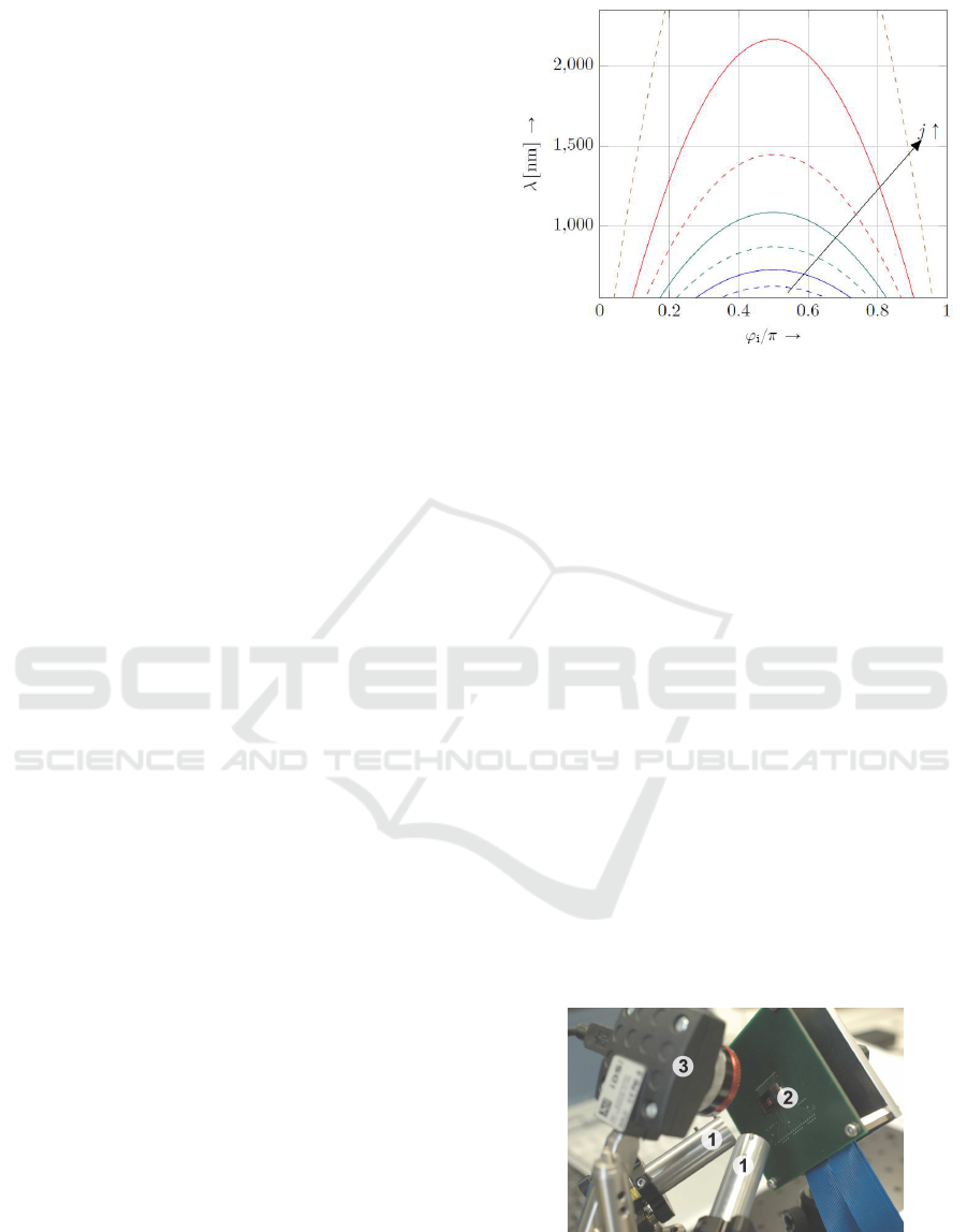
wavelength. To these results regressions on the previ-
ously sorted sets were made assuming analytic func-
tions of quadratic form
λ “ f
j
pθ
i1
“ 11{30 ¨ π, ϕ
i
q “
”
λ
m
pϕ
i1
´ π{2q
2
` λ
o
ı
¨ 10
´9
.
(17)
The results for the regression parameters λ
m
and λ
o
are given in Tab. 2. The family of curves is given in
Fig. 3.
With this result one can directly determine op-
timal coupling parameters for an operating wave-
length. The choice, which curve has to be chosen,
is a trade off between stability around this operating
Figure 3: Illustration of Tab. 2.
wavelength, e.g., for wavelength division multiplex-
ing systems, and the mechanical stability of the setup.
The flatter the slope of the curve in a chosen working
point the more stable is the mechanical setup against
variations of the positioning. In contrast, the steeper
the curve the higher is the stability for wavelengths
around this point.
6 REALIZATION AND RESULTS
Fig. 4 shows the first version of the experimental
setup. Two collimating lenses
l
1
widen the signal
carrying light at the end of two SMFs to two colli-
mated laser beams. These two beams are reflected at
the DLP
l
2
, where a previously assigned bit map de-
termines the tilt pattern of the underlying MMA. This
consequently decides which source later activates low
and which source high order modes, respectively. The
camera UI-1240LE
l
3
measures the reflected laser
beam pattern at the main output direction, which will
be later replaced by an optic focusing the light pattern
onto an attached MMF.
Figure 4: Experimental setup.
The first proof of concept has been made using
visible light with wavelength λ “ 675nm. Therefore,
the camera gives a more detailed and intuitive insight
OPTICS 2016 - International Conference on Optical Communication Systems
22
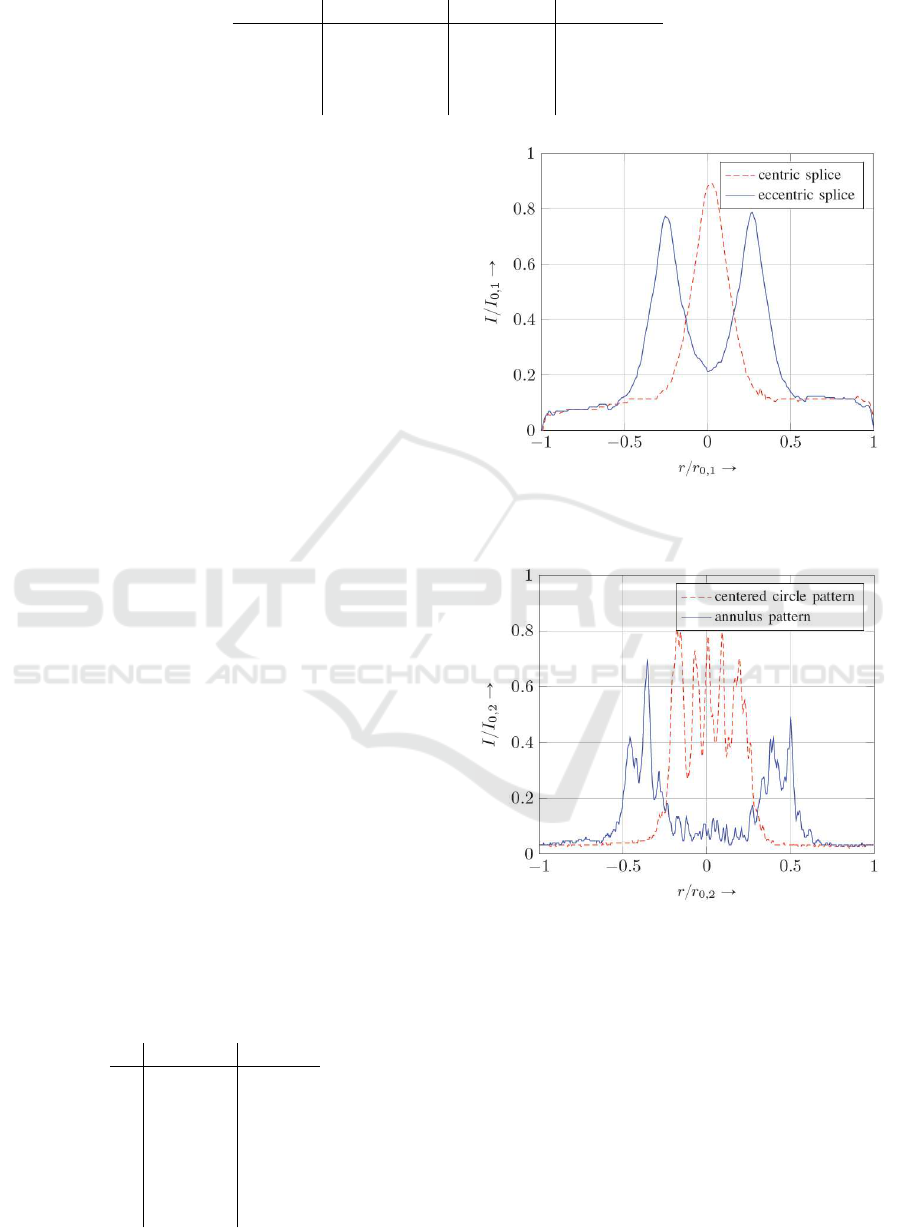
Table 1: Optimal coupling parameters of two sources arranged in front of the DLP.
λ ϕ
i1{i2
¨ 180{π θ
i1
¨ 180{π θ
i2
¨ 180{π
675nm 36.025 66.025 113.975
778nm 44.600 65.650 114.350
1326nm 38.000 66.375 113.625
1576nm 46.125 66.000 114.000
into the mechanical structure and its optimization pa-
rameters. The setup has two orthogonal degrees of
freedom for each source as previously mentioned:
θ
i1{i2
and ϕ
i1{i2
. As the experiment is realized using
standard optical adjustment components, the param-
eters, which can be varied, are not orthogonalized to
each other. The adjustment becomes an iterative pro-
cess, which is easier achievable for visible light. The
optimized parameters ϕ
i1
“ ϕ
i2
« 0.62π, θ
i1
« 0.37π
and θ
i2
« 0.63π which are chosen from Tab. 2 curve
j “ 2.
The DLP was programmed with a bitmap with
an inner circle of ones and zeros around this circle.
Hence, one source is seen as a circle on the MMA
from the camera, the other one as the corresponding
annulus. For the evaluation process the camera took
pictures from each source while the parallel source
was switched off. Through these pictures a vertical
cut was taken to look at the light intensity as a func-
tion of the radius. By looking at the orthogonality of
the curves generated by the different sources one can
conclude to the capability of SDM of this setup. To
have a better reference, these curves are compared to
light intensity distributions measured at the end sur-
face of a 1.4km MMF. The different distributions are
obtained by splices of SMFs to MMFs with centred
and offset launching conditions and a subsequent fu-
sion coupler for the mode combining process into that
MMF as used in the OMIMO testbed in (Sandmann
et al., 2014). Fig. 5 and 6 show the field pattern of the
measurements.
Fig. 5 shows the intensity distribution over a ver-
tical cut through a surface of a MMF. The red dashed
curve is the distribution produced by a centric splice
as described and the blue solid curve produced by an
18µm eccentric splice. The graph shows well sepa-
Table 2: Analytic functions of shape (17) to obtain optimal
coupling parameters using the DLP.
j λ
m
rnms λ
o
rnms
1 ´311.0 624.5
2 ´354.9 728.1
3 ´415.1 872.3
4 ´507.5 1088.0
5 ´666.7 1448.0
6 ´994.0 2167.0
7 ´1604.0 3886.0
Figure 5: Cut through light intensity measurements: Mode
field pattern realized by a fusion coupler with center and
offset launch condition.
Figure 6: Cut through light intensity measurements: Mea-
sured DLP-controlled output pattern.
rated low and high order modes as expected. In con-
trast to Fig. 5, Fig. 6 represents vertical cut through
pictures acquired by the camera. For the red dashed
curve a centred circle pattern is set to the DLP, for
the blue solid curve the corresponding annulus. Note
that the parameters I
0,1{0,2
as well as r
0,1{0,2
are nor-
malizing constants taken from the measured bit map
acquired by different sensors, which only allows a
conclusion about relative power distribution within
one graph rather than absolute power distribution or
a comparison between both graphs with respect to the
Digital Mirror Devices for Mode Selective Excitation in Multimode Fibers
23

measured power.
In Fig. 6, the profile is disturbed by fridges. They
originate from a non-optimal anti-reflection coating
of the protection window attached to the DLP. An ad-
ditional difficulty appears if one compares the left and
right maximum of the annulus which are different in
their intensity. The differences is related to the me-
chanical setup which was not able to match the opti-
mal coupling conditions as described in Sec. 5, per-
fectly. Nevertheless, a clear separation of both curves
can be seen as good as in Fig. 5. This meets the re-
quirement such that the inner source excites low order
modes and the outer source high order modes if both
sources are concurrently stimulated and the reflected
pattern is focused onto a MMF. An advantage of the
mode coupling technique utilizing the DLP compared
to the splices concatenated with fusion coupler is that
the ratio between the inner circle and the outer one
can be freely chosen by the tilt pattern of the MMA
and is not fixed. Moreover, the achievable theoretical
power loss of L
DLP
« ´1.27dB of our setup is far less
than L
SLM
« ´3dB for a two step serial concatenation
of SLMs.
7 CONCLUSION
This paper shows how mode group specific excitation
in a MMF can be realized using a DMD. The under-
lying MMA combines two different mode groups si-
multaneously. Therefore, the DMD features advan-
tages of SLM techniques and fusion couplers while
avoiding their specific drawbacks – a controllable
mode specific and parallel excitation while having a
low insertion loss. Since the MMA is a blazed grat-
ing finding the optimal incident angles to the DMD is
a complex task. A first proof of the concept is done
with visible light. The field pattern of the reflected
light of each was captured by a camera to evaluate
their orthogonality. Similar to the mode field pat-
tern achieved by offset splices of SMF and MMF the
curves of the light intensity distribution generated by
different sources are well separated. Hence, the po-
tential of using DMDs for mode selective excitation
in a MMF has been demonstrated.
REFERENCES
Berdagué, S. and Facq, P. (1982). Mode division multiplex-
ing in optical fibers. Appl. Opt., 21(11):1950–1955.
Goodman, J. W. (2005). Introduction to Fourier Optics. The
McGraw-Hill Companies, Inc., 2nd edition.
Gu, R. Y., Ip, E., Li, M.-J., Huang, Y.-K., and Kahn, J. M.
(2013). Experimental demonstration of a spatial light
modulator few-mode fiber switch for space-division
multiplexing. In Frontiers in Optics 2013 Postdead-
line. Optical Society of America.
Harvey, J. E. and Vernold, C. L. (1998). Description of
diffraction grating behavior in direction cosine space.
Appl. Opt., 37(34):8158–8159.
Hayat, G. S. Handbook of diffraction gratings - ruled and
holographic. JOBIN-YVON S.A.
Hsu, R., Tarighat, A., Shah, A., Sayed, A., and Jalali, B.
(2006). Capacity enhancement in coherent optical
MIMO (COMIMO) multimode fiber links. Commu-
nications Letters, IEEE, 10(3):195–197.
Hsu, R. C. J., Shah, A., and Jalali, B. (2004). Coherent op-
tical multiple-input multiple-output communication.
IEICE Electronics Express, 1(13):392–397.
Instruments, T. (2008). Using lasers with DLP DMD tech-
nology. Technical report, Texas Instruments.
Ryf, R., Fontaine, N. K., Mestre, M. A., Randel, S., Palou,
X., Bolle, C., Gnauck, A. H., Chandrasekhar, S., Liu,
X., Guan, B., Essiambre, R.-J., Winzer, P. J., Leon-
Saval, S., Bland-Hawthorn, J., Delbue, R., Pupalaikis,
P., Sureka, A., Sun, Y., Grüner-Nielsen, L., Jensen,
R. V., and Lingle, R. (2012). 12 ˆ 12 MIMO trans-
mission over 130-km few-mode fiber. In Frontiers
in Optics 2012/Laser Science XXVIII, page FW6C.4.
Optical Society of America.
Sandmann, A., Ahrens, A., and Lochmann, S. (2014). Ex-
perimental description of multimode mimo channels
utilizing optical couplers. In Photonic Networks; 15.
ITG Symposium; Proceedings of, pages 1–6.
Schollmann, S., Schrammar, N., and Rosenkranz, W.
(2008). Experimental realisation of 3 ˆ 3 MIMO sys-
tem with mode group diversity multiplexing limited
by modal noise. In Optical Fiber communication/-
National Fiber Optic Engineers Conference, 2008.
OFC/NFOEC 2008. Conference on, pages 1–3.
Shah, A., Hsu, R., Tarighat, A., Sayed, A., and Jalali, B.
(2005). Coherent optical MIMO (COMIMO). Light-
wave Technology, Journal of, 23(8):2410–2419.
Tang, K.-T. (2007). Mathematical Methods for Engineers
and Scientists 2. Springer-Verlag Berlin.
Yoder, L. A., Duncan, W. M., Koontz, E. M., So, J., Bartlett,
T. A., Lee, B. L., Sawyers, B. D., Powell, D., and Ran-
curet, P. (2001). DLP technolgy: applications in op-
tical networking. In SPI Proceedings, volume 4457,
pages 54–61.
OPTICS 2016 - International Conference on Optical Communication Systems
24
