
Evaluation of Foveated Stereo Matching for Robotic Cloth Manipulation
Tian Xu and Paul Cockshott
School of Computing Science, University of Glasgow, 17 Lilybank Gardens, G12 8RZ, Glasgow, U.K.
Keywords:
Stereo Matching, Robotic Vision, Foveated Matching, Cloth Manipulation, Grasp, Flatten, Evaluation, GPU.
Abstract:
Due to the recent development of robotic techniques, cloth manipulation has become an important task. Stereo
matching forms a crucial part of the robotic vision and aims to derive the depth information from the image
pairs captured by the stereo cameras. However, processing high resolution images to capture sufficient details
meanwhile in real-time is very challenging. In addition to accelerating by current multi-core GPU infrastruc-
ture, in this work, we utilize foveated matching algorithm to improve the efficiency. To study the effect of
foveated matching algorithm on two common robotic manipulation tasks, cloth grasping and flattening, we
first create a “garment with wrinkle” dataset that includes depth map ground-truth for garments, which is to
our knowledge not available in the research community. Secondly, using this dataset, we found that foveated
matching is effective in trading off accuracy for efficiency for stereo matching. Finally, by assuming the
robotic behavior following previous work for both cloth grasping and flattening tasks, we demonstrate that
using foveated matching can achieve the same level of accuracy for completing both tasks with two to three
times of acceleration.
1 INTRODUCTION
Robotic cloth manipulation has become a research
area in recent years with various attempts being made
to enable a robot to grasp (Maitin-Shepard et al.,
2010; Ramisa et al., 2012), flatten (Sun et al., 2015;
Cusumano-Towner et al., 2011; Doumanoglou et al.,
2014), fold (Bersch et al., 2011; Van Den Berg et al.,
2011) or unfold (Willimon et al., 2011b) clothes with
wrinkles on them. One common challenge of all
those tasks is to develop a robotic vision system that
is able to perceive the clothes with sufficient de-
tail, to allow the robotic components to manipulate
them (e.g. grasping the cloth wrinkles). One common
class of robotic vision system is constructed by two
cameras with depth information extracted by stereo
matching algorithms (Scharstein and Szeliski, 2002).
However, the stereo matching task in this context
is quite challenging. Robotic vision requires accurate
depth output in a relatively short timespan in order to
perform cloth manipulations in real-time. For exam-
ple, for the task of cloth flattening (Sun et al., 2015),
the robotic vision system needs to detect any wrin-
kles that are larger than 5mm in order to smooth the
wrinkles. High resolution images (16 mega pixels)
are captured to allow analysis of the garment’s sur-
face. In these circumstances, where high resolution
images are required, stereo matching efficiency be-
comes a rate limiting factor. It was shown previously
that performing stereo matching on the Middlebury
high resolution full size images (around 6 mega pix-
els) (Scharstein et al., 2014) can cost almost around
30 seconds to finish one matching for most of the
proposed algorithms
1
. Although there have been a
few attempts to utilize multi-core architectures such
as GPU or CPU to accelerate matching (Mei et al.,
2011; Xu et al., 2014; Xu and Cockshott, 2015), in
order to achieve the level of efficiency required, the
best performing techniques are still too slow for real-
time use.
Rather than relying on faster computational hard-
ware, another straightforward way to reduce com-
putation time is to work with coarse resolution im-
ages but this restricts the acquisition of detailed in-
formation. A better solution, inspired by biologi-
cal systems, is the use of eye movement together
with foveated retinas (Boyling and Siebert, 2000;
Bernardino and Santos-Victor, 2002). The visual sys-
tem of amniotes has a space-variant nature where
the resolution is high on the fovea (the center of the
retina) and decreases gradually to the periphery of the
visual field. By moving the high resolution fovea we
get a detailed representations of our environment. A
few approaches have already been proposed to com-
1
http://vision.middlebury.edu/stereo/eval3/.
Xu, T. and Cockshott, P.
Evaluation of Foveated Stereo Matching for Robotic Cloth Manipulation.
DOI: 10.5220/0005727506570664
In Proceedings of the 11th Joint Conference on Computer Vision, Imaging and Computer Graphics Theory and Applications (VISIGRAPP 2016) - Volume 3: VISAPP, pages 657-664
ISBN: 978-989-758-175-5
Copyright
c
2020 by SCITEPRESS – Science and Technology Publications, Lda. All rights reserved
657

pute disparity maps for foveated active vision systems
using, for example, a foveated pyramid representation
(Boyling and Siebert, 2000) or a logmap based dense
representation (Bernardino and Santos-Victor, 2002).
These approaches can be referred as foveated stereo
matching.
In this work, we aim to evaluate the performance
of the pyramid-based foveated matching in terms of
both matching accuracy and efficiency, in the context
of robotic cloth manipulations. Specifically, we aim
to answer whether foveated matching can be used to
accelerate the job while being accurate enough, for
two robot cloth manipulation tasks: flattening and
grasping. We performed simulations of cloth wrin-
kles to obtain depth map ground-truths for accuracy
evaluation as, to our knowledge, no public testbed is
available for this purpose. Using the dataset and as-
suming (following previous work (Sun et al., 2015;
Ramisa et al., 2012; Maitin-Shepard et al., 2010)) the
required stereo matching accuracy and robotic behav-
ior for the two tasks, we determine when foveated
matching is sufficient to accomplish the given task.
Specifically, we find that using foveated matching we
can achieve the same level of accuracy for both tasks
at two to three times the speed of the non-foveated
version. In addition, we compare foveated matching
with the simple solution of just utilizing low resolu-
tion images, in terms of the accuracy versus efficiency
trade off.
2 FOVEATED MATCHING
ALGORITHM
We implemented a parallel extension of Boyling’s
foveated pyramid matching algorithm (Boyling and
Siebert, 2000). Two image pyramids with gaussian
smoothing are first built for the input left and right
image. A correlation-based matching process de-
scribed in (Xu et al., 2014) is computed at a low res-
olution to generate initial estimate for the disparity
and the initial disparity estimate from this scale is re-
fined at higher resolutions until the target resolution
is achieved.
In this paper, as we descend the pyramid, the
correlation-based matching is performed until we
reach a particular level, which is called the foveated
level f ( for example f =3 in figure 1). Let us, for
the sake of argument, assume that the foveated level
is 400 by 300 pixels. Clearly, by the properties of an
image pyramid, this level contains information about
the whole scene but with reduced resolution. With the
standard pyramid matcher, the following level, called
level f −1 ( f −1=2 in figure 1), would be larger by a
Figure 1: Pyramid representation of stereo input image to
perform foveated matching at multiple scales.
factor of
√
2 on edge, giving a pyramid plane of 566
by 424. In the foveated matcher (Boyling and Siebert,
2000), we retain only a central block of the same size
as level f . The margins between this 400x300 block
and the 566x424 plane are simply discarded as shown
in figure 1. Clearly the 400x300 block in level f −1
will only include information about the central part of
the scene in level f , but will contain this in more de-
tail than in level f . The field of view shrinks but the
level of detail increases.
Suppose we have some matching algorithm M
which can be applied to a full resolution pyra-
mid, then this same algorithm can be applied to
the foveated pyramid, except that with the foveated
case, it works on less data, because part of the im-
age data has been discarded. In this paper, the
same correlation-based matching algorithm that was
used on the full resolution pyramid is applied to the
foveated image pyramid. This gives a stack of dispar-
ity maps for each level l ∈ 0.. f . This stack is the out-
put. This stack of foveated matching disparity maps
contains less data than the normal pyramid of dispar-
ity maps. Suppose the original size image contains N
pixels, and the pyramid’s scale factor for width and
length is
√
2, then the scale factor for image is 2. If
there is in total K levels for the pyramid and level F
is chosen to be the foveated level, then the sum of
pixel number processed for the normal pyramid (S
Nor
)
could be calculated as
S
Nor
= N +
1
2
N + (
1
2
)
2
N + ···+ (
1
2
)
(F−1)
N
+···+ (
1
2
)
(K−1)
N
= N ·
1 −(
1
2
)
K
1 −(
1
2
)
(1)
and the sum of pixel number processed for the
foveated pyramid (S
Fov
) is
VISAPP 2016 - International Conference on Computer Vision Theory and Applications
658

S
Fov
= (
1
2
)
(F−1)
N + (
1
2
)
(F−1)
N + ···+ (
1
2
)
(F−1)
N
+···+ (
1
2
)
(K−1)
N
= N ·F ·(
1
2
)
(F−1)
+ N ·(
1
2
)
F
·
1 −(
1
2
)
(K−F)
1 −(
1
2
)
(2)
so the ratio of processed number of pixels between
those two methods can be calculated as
S
Fov
S
Nor
=
(
1
2
)
F
(F + 1) −(
1
2
)
K
1 −(
1
2
)
K
(3)
The ratio S
Fov
/S
Nor
for the example in figure 1 is 0.47,
which means more than half of the data has been dis-
carded. If the pyramid level increases to for example
14 levels, and we choose level 5 as foveated level,
then the ratio will be 0.19, which decreases the data
size significantly for stereo matching process.
Another data representation is to post process the
stack of foveated disparity maps to generate the full
size disparity map of foveated matching, which has
the same size as the original input left and right im-
ages. This option makes it easier to compare the accu-
racy performance with the standard full field matcher,
so it is chosen for our experiments. The disparity map
of foveated level f ( f =3 as shown in Figure 2), is
expanded to the original resolution of the next level
f −1. Pixels of the central area from f −1 are su-
perimposed on the centre of this expanded disparity
map, which is then expanded again. This process is
repeated until the highest resolution level is reached.
The result is an disparity map which contains high
resolution information in the central area and bor-
dered by concentric areas of decreasing resolution in-
formation.
The disparity map thus obtained could be fur-
ther converted to depth map using a simplified
least-square stereo triangulation routine (Hartley and
Sturm, 1997), given the intrinsic and extrinsic param-
eters of the cameras. The depth map is necessary
because it can give a direct measure of how depth
changes in millimetres, rather than in pixels. This out-
put depth map would have similar character as dispar-
ity map, which contains high resolution information
in the central area and bordered by concentric areas
of decreasing resolution information.
3 EVALUATION
METHODOLOGY
For robotic cloth manipulation, the scene being cap-
tured for the robotic vision system is a wrinkled
Figure 2: Structure of the foveated pyramid and a map of the
spatial resolution of a disparity map created by matching the
foveated pyramid.
garment placed on a table. Although there exist a
few garment related datasets (Aragon-Camarasa et al.,
2013), there is no existing dataset that contains stereo
garment images with depth ground truth. Therefore,
we first focus on generating a simulated dataset for
this purpose, described in section 3.1. Secondly, we
also utilize a set of evaluation metrics to measure
stereo matching effectiveness, both in terms of the
depth map and its effects on robotic manipulation
tasks, described in section 3.2.
3.1 Simulated Cloth Wrinkle Dataset
We generate a dataset to imitate the simplest case,
which is a cloth with one wrinkle on it. A pair of
real images with table covered by cloth (Figure 3) was
used to create the simulated dataset. The cloth is flat
and there is no visible wrinkle on the table area. To
generate the disparity map, the non-foveated match-
ing algorithm is applied on the stereo images. Know-
ing the camera parameters, the corresponding depth
map from the left viewpoint could be generated (Hart-
ley and Sturm, 1997) (Figure 3(c)). Notice that the
generated depth map is not the ground truth, but this
serves as the flattened plane for our wrinkle simula-
tion, i.e. adding wrinkles to this depth map. To imitate
a “bell curve” shaped cloth wrinkle, in this work, we
simply use the Gaussian function for the simulation.
This simulated wrinkle is then added to the depth map
(Figure 3) in order to generate a simulated depth map
with one wrinkle on the cloth (Figure 4). When the
intrinsic and extrinsic camera parameters are known
2
,
the 3D points from depth map could be projected to
the left and right camera view plane using a perspec-
tive transformation:
sx = PX
w
= A[R|t]X
w
(4)
or
s
x
y
1
=
f
x
0 u
0
0 f
y
v
0
0 0 1
r
1
r
2
r
3
t
1
r
4
r
5
r
6
t
2
r
7
r
8
r
9
t
3
X
Y
Z
1
(5)
2
Camera calibration and 3D reconstruction: http://docs.
opencv.org/modules/calib3d/doc/camera calibration and
3d reconstruction.html.
Evaluation of Foveated Stereo Matching for Robotic Cloth Manipulation
659
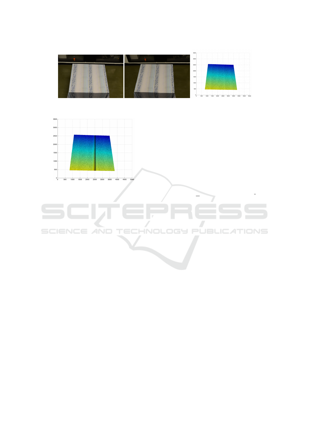
(a) Left image (b) Right image (c) Depth map of left view
Figure 3: The image pair obtained from the stereo robotic camera with the corresponding depth map.
Figure 4: The depth map of simulated cloth wrinkles using
Gaussian function, simulating various cross section shapes.
where P is a projection matrix; A is a 3×3 matrix of
camera intrinsic parameters; Extrinsic parameters are
combined by 3×3 rotation matrix R and 3×1 transla-
tion matrix t; s is a skew parameter; (X ,Y,Z) are the
coordinates of the 3D point in the world coordinate
space while (x,y) are the coordinates of the projec-
tion point in pixels. Knowing the projection positions
on the left and right view plane, the position differ-
ence is treated as the disparity map. By warping the
right image with disparity map, the left image could
be generated. The simulated depth map used to cre-
ate the images can later be used as the ground truth
depth map. Three groups of wrinkles are simulated:
similar wrinkle curve (e.g. width 87 mm and height
84 mm), same width with different heights and same
height with different widths. We in total simulate nine
wrinkles (three for each group). Example of the cloth
wrinkle depth map is shown in Figure 4.
3.2 Evaluation Metrics
3.2.1 Stereo Matching Effectiveness
To evaluate the performance of stereo matching al-
gorithm, one common technique is to compute er-
ror statistics with respect to ground truth data (Bar-
ron et al., 1994). Normally the quality of dispar-
ity map are measured using two general approaches,
percentage of bad matching pixels and root mean
square(RMS) error (Scharstein and Szeliski, 2002).
However, this is not sufficient to understand the effect
of matching algorithm on robotic manipulation tasks,
because the robot needs to know the depth of view in
millimetres, in order to decide for example where to
grasp. So rather than measuring the disparity map, we
choose to evaluate the depth map in order to gain in-
sight with respect to measures that are more related to
and interpretable in terms of, the robot manipulation
tasks.
RMS error (E
RMS
) between the computed depth
map d
C
(x,y) and the ground truth depth map d
T
(x,y)
is used to measure the effectiveness:
E
RMS
= (
1
N
∑
(x,y)
|d
C
(x,y) −d
T
(x,y)|
2
)
1
2
(6)
upon which N is the total number of pixels.
Depending on the area where we calculate E
RMS
upon, we can obtain different insights on the stereo
matching performance. Since our work mainly fo-
cuses on recognizing wrinkles for robotic manipu-
lation tasks, we are mostly interested in the perfor-
mance within the wrinkle area and the wrinkle ridge.
The wrinkle area is the area of the entire wrinkle that
corresponds to the wrinkle width and length we sim-
ulated. The wrinkle ridge only focuses on the wrinkle
ridge points (highest points) and its small surrounding
area (± 3 pixels).
3.2.2 Robotic Manipulation Tasks
Our ultimate goal is to evaluate the effect of foveated
stereo matching on the precision of various robotic
manipulation tasks. The most straightforward way to
evaluate this is to plug the different foveated match-
ing of various levels (with different accuracy and ef-
ficiency) into the robotic system and then track the
manipulation task performance. Although this pro-
vides the real effects of stereo matching on robotic
manipulations, it is time-consuming to conduct this
evaluation with lots of garment images. In addition,
when evaluating stereo matching, we may also need
to take other factors that may affect the robotic per-
formance (such as camera calibration errors) into ac-
count. Therefore, as our first step, this paper fo-
VISAPP 2016 - International Conference on Computer Vision Theory and Applications
660

cuses on simulating this evaluation. Specifically, we
conduct the simulation by assuming the relationships
(following previous work) between the stereo match-
ing and two robotic manipulation tasks, i.e. grasp-
ing and flattening. We leave the work of conducting
this evaluation on real robotic manipulations in future
work.
For a given version of the foveated stereo match-
ing, by having several trials on multiple cloth images
with different wrinkles in our datasets, we are able to
track the failure rate (FR) of the robotic manipulation
(1−precision), i.e. out of how many trials (number of
stereo image pairs in our dataset in this case) the given
foveated stereo matching can fail the robotic manip-
ulation task given the assumptions we made (as de-
scribed below).
FR =
1
N
∑
i∈I
N
f ailure(i) (7)
where N is the number of trials, I
N
is the set of stereo
image pairs in our dataset and f ailure(i) is the indi-
cator function representing whether a given trial for
the image pair i is a failure. Next, we describe be-
low how we define this f ailure(i) function for both
cloth grasping and flattening tasks respectively in our
simulation.
For the cloth grasping task, a graspable point
is selected based on depth information. The most
commonly used way to ensure that a point is gras-
pable is by selecting the one that maximizes height
(Maitin-Shepard et al., 2010; Willimon et al., 2011a;
Cutkosky, 2012; Ramisa et al., 2012). Therefore,
we make several assumptions on whether the robotic
gripper can succeed in grasping the cloth given the
estimated depth map: (1). the gripper can not grasp
the cloth if the vertical difference between the height
of the estimated highest depth point and the ground-
truth height of the highest point is more than 10mm;
(2). the gripper can not grasp the cloth if the hori-
zontal difference between the estimated highest point
and the ground-truth highest point is more than 5mm.
Only when both criteria are satisfied, is the robot able
to succeed in grasping the cloth. Since this setting can
vary across different robotic grippers or systems, we
therefore assume the more restrictive setting.
For the cloth flattening task, based on the average
of manually flattened garment examples performed by
a human, it has been shown that (Sun et al., 2015) if
the detected wrinkles are less than 5mm, the garment
is deemed to be flattened. Therefore, we assume that
the stereo matching is required to at least achieve the
RMS below 5mm on the wrinkle ridges in order to
recognize small wrinkles of around 5mm whilst not
falsely recognizing plane areas as wrinkles.
4 EXPERIMENTS
Our experiments are implemented in the following
ways. The resolution of the stereo image pairs used in
our work is fairly large, i.e. we utilize 16 Mega (4928
×3264) pixel colour images. The subsample factor of
image pyramid is
√
2 in linear dimensions, and in to-
tal we utilize 14 levels for the pyramid. The foveated
matching algorithm is implemented using a 4-core In-
tel Core i5-2400, 3.1 GHZ computer. The GPU is a
GeForce GTX770 graphics card with 4GB of memory
from NVIDIA. We used the CUDA (Compute Unified
Device Architecture) technique from NVIDIA Corpo-
ration for implementation on the GPU.
4.1 Evaluating Matching Effectiveness
To evaluate how effectiveness (accuracy) of the depth
map changes with the foveation level, in this section,
we rate the foveated stereo matching in terms of both
the wrinkle area and the wrinkle ridge (defined in sec
3.2.1). Note that when the foveated level is selected to
be 1, the effectiveness of the foveated matching is the
same as the one applying non-foveated matching al-
gorithm. In this experiment, for the sake of simplicity
and clarity, we choose to only perform on a wrinkle of
87 mm width and 84 mm height we simulated (as we
found similar results for other simulated wrinkles).
4.1.1 Wrinkle Area Evaluation
Figure 5(a) presents the RMS evaluation results of the
foveated matching algorithm applied to full size im-
ages for each selected foveated level within the wrin-
kle area. As for foveated matching (see Figure 2),
since the depth map contains its finest information in
the central area and more coarse information in the
border area, we therefore report three different per-
formance aspects. “Fov boundary area” only consid-
ers points that contain coarsest wrinkle information
while “Fov central area” focuses on the evaluation of
central points only that contain finest wrinkle infor-
mation. “Fov expectation” represents the mathemat-
ical expectation of the performance over the whole
wrinkle.
Comparing those three aspects, not surprisingly,
we observe that for the foveated matching algorithm
at various levels, the central area can always achieve
very high accuracy, with RMS always below 5mm
in the wrinkle area. As the foveated level increases,
the RMS error on the coarsest level of the foveated
matcher (“Fov
boundary area”) increases dramati-
cally. This trend is not so significant when the
foveated level increases from 1 to 7 and the RMS er-
ror is relatively stable and still always below 5mm.
Evaluation of Foveated Stereo Matching for Robotic Cloth Manipulation
661
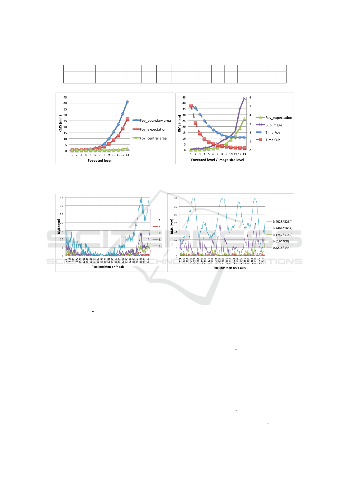
Table 1: Mapping between each foveation level to the image resolution.
Foveated Level 1 2 3 4 5 6 7 8 9 10 11 12 13 14
Height 4928 3485 2464 1742 1232 871 616 436 308 218 154 109 77 54
Width 3264 2308 1632 1154 816 577 408 288 204 144 102 72 51 36
(a) Accuracy evaluation of foveated matching algorithm ap-
plied to full size images.
(b) Efficiency and accuracy comparison between two strategies
(Foveated & Low resolution matching).
Figure 5: Accuracy and efficiency performance on foveated stereo matching on wrinkle area.
(a) Performance for different foveated levels. (b) Performance for different image size levels.
Figure 6: Accuracy performance with different foveated/ image size level along with the wrinkle ridge.
However, for the foveation above 10 levels, the RMS
error increases rapidly (varying from around 20mm
to 40mm). The “Fov expectation” follows the similar
trend. This suggests that foveated matching with 10
and more levels according to our settings is definitely
not recommended for accuracy.
As we mentioned, applying foveated matching al-
gorithm on stereo images is not the only way to im-
prove the efficiency as the most straightforward ap-
proach is using smaller resolution images, then con-
ducting standard (i.e. non-foveated) stereo matching.
In order to have fair comparison between the two
strategies, the original size (4928 × 3264 pixels)
image is continually subsampled by a factor of
√
2
in linear dimensions, to build image pairs of differ-
ent resolutions, following the 14-level image pyramid
strategy. Table 1 presents the mapping between the
foveation level to the image resolution. Note that for
each level, the image resolution (size) corresponds to
coarsest (boundary) image resolution within the given
foveated level.
Therefore, non-foveated matching algorithm
(i.e. foveated stereo matching algorithm assuming
foveation level is 1) is applied on image pairs of
different resolutions (“Sub Image”) and the effec-
tiveness performance is shown in Figure 5(b), in
comparison with “Fov expectation”. We also report
the efficiency results. Note that the images of differ-
ent resolutions is obtained by subsampling from the
original stereo images with Gaussian smoothing to
attenuate high frequency noises. In terms of matching
effectiveness, we can observe that the performance
curve of “Sub Image” shows the trend that when the
image size decreases, the RMS error of depth map
increases. It is clear that “Sub image” always has
larger error than “Fov
expectation” for all different
foveation level (or image resolution) while it has
comparable performance with “Fov boundary area”.
VISAPP 2016 - International Conference on Computer Vision Theory and Applications
662

With respect to efficiency, “Time sub” is the corre-
sponding efficiency for the matching with different
image resolutions while “Time Fov” is the efficiency
trend for foveated matching process. We can observe
that comparing two efficiency curve, it indicates that
“Time Sub” decreases faster than “Time Fov” while
“Time Fov” can reach the maximum efficiency of
around 1 second. This is because the input images for
foveated matching algorithm are all full size images
(16 mega pixels), therefore part of the process could
not be accelerated, e.g. integrating stack of disparity
maps into full size disparity map, reading and writing
full size image data between CPU and GPU, etc.
Decreasing the foveated matching base image to
smaller resolution (e.g. 4 mega pixels) can reduce the
converging efficiency (time) meanwhile still achieve
better accuracy performance than simply matching
using images of low resolution.
4.1.2 Wrinkle Ridge Evaluation
In the above experiments, RMS error is used to evalu-
ate the depth map accuracy, however, this only shows
the average performance for all points in the specified
wrinkle area. It is hard to know whether the ridge has
been preserved well. In this section, only points close
to the ridge are taken into consideration. Since our
simulated wrinkle is placed vertically along the table,
as shown in Figure 4, for all the depth map points on
the ridge, the X coordinates are all the same. So we
only need to present the depth performance along the
Y-axis (on the table area, ranged from 733 to 2790
pixels). The results are shown in Figure 6.
Figure 6(a) presents the results of foveated stereo
matching on different foveated levels (1, 4, 7, 8, 10)
on the wrinkle ridge. The figure demonstrates that the
error is usually small in the central area but larger in
the borders. This is because central area contains finer
information than borders. We can observe that almost
all the points from foveated level 1 and 4 are less than
5 mm, while about 55% of points from level 10 do not
meet this. For foveation level 7, 4.8% of the points
have an error larger than 5 mm while most of these
points are close to border of the wrinkle. We also no-
tice that the distribution of RMS error in figure 6(a)
is not symmetric, because the fovea of our algorithm
focuses on the center of the image, rather than the cen-
tral of the table. Therefore, when comparing perfor-
mance surrounding the central Y coordinate, which is
1632, the RMS error is roughly symmetric.
For the same wrinkle, ridge performance is also
evaluated for the non-foveated matching algorithm on
images of different resolutions in Figure 6(b). The
RMS error of depth map for level 3 (2464x1632 pix-
els) are all below 5 mm while the RMS error of a
Figure 7: Accuracy performance (failure rate) of two
robotic manipulation tasks (cloth grasping and flattening)
and matching efficiency given various foveation levels.
small part of level 4 depth map is sharp and non-
neglectable. Compared to the performance on the cor-
responding foveated level shown in Figure 6(a), the
performance on the wrinkle ridge is worse for lower
resolution (such as 7 and 10) while the RMS is gen-
erally above 5 to 10mm. This demonstrate that ap-
plying foveated matching can achieve better effective-
ness than simply applying non-foveated matching on
low resolution images.
4.2 Effects of Foveated Matching to
Robotic Cloth Manipulation
In this section, we aim to evaluate the effect of
foveated stereo matching on the final robot manipu-
lation task. Figure 7 presents the results on the fail-
ure rate (1 − precision) of robotic manipulation for
both cloth grasping and flattening tasks for various
foveated levels. Y-axis is the failure rate of the given
robotic manipulation task for the cloth images with
different wrinkles and the x-axis is the foveation level.
Details on the assumptions made for the robotic ma-
nipulation task and how we obtain the failure rate are
given in section 3.2.2.
We can observe that, to achieve better than 80%
flattening task completion (i.e. less than 20% failure
rate), requires a foveation level < 5. With respect
to cloth grasping, this requires a foveation level < 7
to achieve at least 80% task completion. This is not
surprising. It implies that the flattening task is gen-
erally more difficult than the grasping task, and thus
requires lower levels of foveation (more accurate rep-
resentation) in order to finish the task. This further
justifies our choices of assumptions made for the two
tasks. From the efficiency perspective, this shows that
by using foveation to achieve the same level of accu-
racy for completing the robotic cloth flattening and
grasping tasks, we can reduce the running time by ap-
proximately two and three times.
Evaluation of Foveated Stereo Matching for Robotic Cloth Manipulation
663

5 CONCLUSIONS
In this work, we evaluate the performance of a
pyramid-based foveated matcher in terms of both ac-
curacy and efficiency, in the context of robotic cloth
manipulations. By conducting simulations of cloth
wrinkles we obtained depth map ground-truths for
our evaluation. Using this simulated dataset, we
found that foveated matching is effective in trading
off accuracy for efficiency for stereo matching perfor-
mance. In addition, by assuming the robotic behav-
ior described in prior work, we found that the use of
foveation can allow high accuracy for robotic cloth
flattening and grasping tasks with a two to three fold
speed gain.
Note that our work has several limitations: firstly,
we assume that there is only one wrinkle on the cloth.
Secondly, we assume a certain stereo matching accu-
racy is required to achieve the robotic manipulation
tasks. This might vary according to different cloth
materials, wrinkle properties, etc. We leave the work
of dealing with more real cloth wrinkles with real
robotic manipulations (various tasks) as future work.
REFERENCES
Aragon-Camarasa, G., Oehler, S. B., Liu, Y., Li, S.,
Cockshott, P., and Siebert, J. P. (2013). Glasgow’s
stereo image database of garments. arXiv preprint
arXiv:1311.7295.
Barron, J. L., Fleet, D. J., and Beauchemin, S. S. (1994).
Performance of optical flow techniques. International
journal of computer vision, 12(1):43–77.
Bernardino, A. and Santos-Victor, J. (2002). A binocular
stereo algorithm for log-polar foveated systems. In
Biologically Motivated Computer Vision, pages 127–
136. Springer.
Bersch, C., Pitzer, B., and Kammel, S. (2011). Bi-
manual robotic cloth manipulation for laundry fold-
ing. In Intelligent Robots and Systems (IROS), 2011
IEEE/RSJ International Conference on, pages 1413–
1419. IEEE.
Boyling, T. and Siebert, J. (2000). A fast foveated stereo
matcher. In Proc. Conf. on Imaging Science Systems
and Technology, pages 417–423.
Cusumano-Towner, M., Singh, A., Miller, S., O’Brien,
J. F., and Abbeel, P. (2011). Bringing clothing into
desired configurations with limited perception. In
Robotics and Automation (ICRA), 2011 IEEE Inter-
national Conference on, pages 3893–3900. IEEE.
Cutkosky, M. R. (2012). Robotic grasping and fine manipu-
lation, volume 6. Springer Science & Business Media.
Doumanoglou, A., Kim, T.-K., Zhao, X., and Malassio-
tis, S. (2014). Active random forests: An applica-
tion to autonomous unfolding of clothes. In Computer
Vision–ECCV 2014, pages 644–658. Springer.
Hartley, R. I. and Sturm, P. (1997). Triangulation. Computer
vision and image understanding, 68(2):146–157.
Maitin-Shepard, J., Cusumano-Towner, M., Lei, J., and
Abbeel, P. (2010). Cloth grasp point detection based
on multiple-view geometric cues with application to
robotic towel folding. In Robotics and Automa-
tion (ICRA), 2010 IEEE International Conference on,
pages 2308–2315. IEEE.
Mei, X., Sun, X., Zhou, M., Jiao, S., Wang, H., and Zhang,
X. (2011). On building an accurate stereo matching
system on graphics hardware. In Computer Vision
Workshops (ICCV Workshops), 2011 IEEE Interna-
tional Conference on, pages 467–474. IEEE.
Ramisa, A., Alenya, G., Moreno-Noguer, F., and Torras, C.
(2012). Using depth and appearance features for in-
formed robot grasping of highly wrinkled clothes. In
Robotics and Automation (ICRA), 2012 IEEE Interna-
tional Conference on, pages 1703–1708. IEEE.
Scharstein, D., Hirschm
¨
uller, H., Kitajima, Y., Krathwohl,
G., Ne
ˇ
si
´
c, N., Wang, X., and Westling, P. (2014).
High-resolution stereo datasets with subpixel-accurate
ground truth. In Pattern Recognition, pages 31–42.
Springer.
Scharstein, D. and Szeliski, R. (2002). A taxonomy and
evaluation of dense two-frame stereo correspondence
algorithms. International Journal of Computer Vision,
47(1-3):7–42.
Sun, L., Aragon-Camarasa, G., Rogers, S., and Siebert, J.
(2015). Accurate garment surface analysis using an
active stereo robot head with application to dual-arm
flattening. In Robotics and Automation (ICRA), 2015
IEEE International Conference on, pages 185–192.
Van Den Berg, J., Miller, S., Goldberg, K., and Abbeel, P.
(2011). Gravity-based robotic cloth folding. In Algo-
rithmic Foundations of Robotics IX, pages 409–424.
Springer.
Willimon, B., Birchfield, S., and Walker, I. (2011a). Clas-
sification of clothing using interactive perception. In
Robotics and Automation (ICRA), 2011 IEEE Interna-
tional Conference on, pages 1862–1868. IEEE.
Willimon, B., Birchfield, S., and Walker, I. D. (2011b).
Model for unfolding laundry using interactive percep-
tion. In IROS, pages 4871–4876.
Xu, T. and Cockshott, P. (2015). Guided filtering based
pyramidical stereo matching for unrectified images.
In Image and Vision Computing New Zealand, In-
ternational Conference, IVCNZ 2015, Auckland, New
Zealand.
Xu, T., Cockshott, P., and Oehler, S. (2014). Acceleration of
stereo-matching on multi-core cpu and gpu. In IEEE
Intl Conf on High Performance Computing and Com-
munications, pages 108–115. IEEE.
VISAPP 2016 - International Conference on Computer Vision Theory and Applications
664
