
Amplitude Modulation by Superposition of Independent Light Sources
Gilbert Johannes Martin Forkel and Peter Adam Hoeher
Information and Coding Theory Lab, Christian-Albrechts-Universit¨at zu Kiel, Kiel, Germany
Keywords:
Superposition, Light-emitting Diodes, Lighting, High-order Modulation, Visible Light Communication,
Modulation, Error Statistics, Optical Communication, Diversity.
Abstract:
Visible light communication (VLC) is a promising alternative to radio waves, when high data rates are required
over short distances. Using lighting equipment for communication offers very high receive power values
without consuming additional energy than already required for illuminating the environment. The bandwidth
restriction of the employed light-emitting diode (LED) light sources is one limiting factor to exploiting the
channels potential capacity. In this paper, we propose spatially distributed modulation schemes to increase
the data rate by switching the LEDs of the lighting equipment individually. Towards this goal, three different
techniques for superposition of independent light sources are compared.
1 INTRODUCTION
Since the beginning of wireless communications, sig-
nal amplitudes have been used to represent informa-
tion. In contrast thereto for visible light communi-
cation, where typically light-emitting diodes are used
as transmitters, modulation shemes with two ampli-
tude levels, like on-off keying (OOK) and pulse-
position modulation (PPM), offer specific advantages.
For intensity modulation, the non proportional volt-
age to optical output power dependency of LEDs has
to be taken into account and power-efficient ampli-
fier designs are challenging. Another advantage of
switched operation is that it is already implemented
as pulse-width modulation in many lighting applica-
tions to control the brightness level and could be eas-
ily adopted for additional communication purposes.
In this publication, we introduce superposition
amplitude modulation (SAM), i.e. to use an array of
individually switchable LEDs in such a manner that,
taking the channel characteristics into account, a uni-
polar amplitude-shift keying (ASK) constellation is
created at the receiver.
In the following, we restrict ourselves to interpret
the amplitude coefficientsas constellation points of an
ASK constellation. Besides this use, the amplitudes
can also be interpreted as the quantized representation
of a positive and real-valued discrete-time signal en-
abling the use of other modulation techniques as well.
An alternative to the proposed scenario, where
each LED is switched individually, one could sug-
gest to modulate the light intensity (compare (Tsonev
et al., 2014; Cossu et al., 2012; Vuˇci´c et al., 2010b)).
A comparison of SAM to discrete multitone transmis-
sion (DMT) is given in Section 6.
There are alternative approaches known from lit-
erature to increase R that can be combined with the
proposed solution but require additional hardware ef-
fort. These methods exploit diversity in space or fre-
quency, e.g. by using multiple LED colors (Cossu
et al., 2012).
The remainder of this paper is organized as fol-
lows: In Section 2 the physical channel for visible
light communication, with a special focus on the su-
perposition of independent LED light sources, is in-
troduced. The main contribution of this work is pre-
sented in Section 3, with three different superposi-
tion schemes that enable us to create an amplitude-
modulated signal at the receiver. In Section 4 the ac-
curacy of the SAM methods is analyzed. Based on
these results the achievable data rates are discussed
and the section is concluded with the presentation of
some promising simulation results on the symbol er-
ror rate (SER) and the peak to average power ratio
(PAPR). Finally measurement results are presented
to justify the assumptions made in Section 3 and the
paper is concluded with a comparison to alternative
intensity-modulation/direct-detection (IM/DD) VLC
modulation methods.
29
Martin Forkel G. and Hoeher P..
Amplitude Modulation by Superposition of Independent Light Sources.
DOI: 10.5220/0005542700290035
In Proceedings of the 6th International Conference on Optical Communication Systems (OPTICS-2015), pages 29-35
ISBN: 978-989-758-116-8
Copyright
c
2015 SCITEPRESS (Science and Technology Publications, Lda.)

2 FUNDAMENTALS
Without loss of generality, we assume rectangular
pulses with equal symbol duration T for all N in-
dividually switchable light sources with optical out-
put power Pt
n
, 0 ≤ n ≤ N − 1. When using direct-
detection the light waves constructively overlap at
the photo detector such that the received signal is
a linear superposition of all light sources and paths.
Consequently, the constituted symbol constellations
A are uni-polar and real-valued. We assume that all
LEDs can be switched independentlywith s
n
∈ {0,1}.
Hence, the received signal power of the nth LED can
be written as
Pr
n
= s
n
Z
T+τ
0
τ
0
L
∑
l=0
y
l,n
(t)dt, (1)
where y
l,n
(t) is the instantaneous receive power am-
plitude of the n’th LED via an l-times reflection path.
L is the maximum number of reflections to consider
and τ
0
is the delay of the shortest path.
Typically, bi-directional communication with a
strong asymmetry of up- and downlink can be found
in visible light communication systems due to the
high brightness level of ceiling lights and restrictive
power requirements in mobile devices. For example,
a low-speed infrared uplink channel is proposed in
(O’brien et al., 2008, IV-B) that could be used to ex-
change channel coefficient measurements.
3 IDENTIFICATION OF THE
CONSTELLATION
AMPLITUDES
Next the three methods USAM, EQSAM and
GEOSAM are introduced that generate the constel-
lation
A = {a
0
,. ..,a
M− 1
} (2)
at the receiver by selectively switching the transmit-
ter light sources and exploiting information about the
physical channel, such as measured channel coeffi-
cients and geometric considerations. For each mod-
ulation scheme, the cardinality M is given as a func-
tion of N, the number of LEDs available. Also the
PAPR is derived for each schema as the mean ratio of
LEDs available to the number of LEDs switched on.
In the following we assume equal probable constella-
tion points.
3.1 USAM: Universal Approach,
Taking Different Path Coefficients
and LED Brightness Levels into
Account
In the general case, we assume that the N light sources
are spatially distributed, e.g. at the ceiling of a room,
and exploit the diverseness of the channel coefficients
to create an universal SAM (USAM) constellation.
The coefficients can be found for example in a train-
ing phase where all LEDs are sequentially switched
on for one symbol duration and, by measuring the
received power, separated into signal part and inter-
symbol interference (ISI) part. These channel esti-
mates are then communicated to the transmitter in a
second step and have to be updated if the environment
changes, e.g. the receiver position is changed.
With the assumption of unique channel coeffi-
cients, the number of possible constellation points can
be derived as
M
USAM
∗
= 2
N
. (3)
Instead of employing an exhaustive search to select M
constellation points closest to the intended ASK con-
stellation from the M
USAM
∗
possible amplitude values
we reduce the complexity by using the following sub-
optimal algorithm:
1. Save receive powers Pr
n
in set C. Variants:
(a) in descending order
(b) in random order
2. The constellation’s extreme values are given as
a
USAM
0
= 0 (4)
a
USAM
M− 1
=
N−1
∑
n=0
Pr
n
. (5)
3. Derive a
USAM
m
for m = 1,.. .,M
USAM
− 2.
The desired amplitude ASK constellation ampli-
tudes d
m
are given with
d
m
=
a
USAM
M− 1
M
USAM
− 1
m. (6)
The approximatedUSAM constellation points can
be found as follows:
a
USAM
m
= 0
foreach c in C do
if a
USAM
m
+ c ≤ d
m
then
a
USAM
m
= a
USAM
m
+ c
end
end
This search method reduces the number of possible
OPTICS2015-InternationalConferenceonOpticalCommunicationSystems
30

combinations to
M
USAM
=
N (N + 1)
2
+ 1. (7)
This simple procedure is close to the optimal solu-
tion, if M
USAM
≪ M
USAM
∗
and a uniform distribution
of the combinatoric combinations can be assumed,
which is valid in most cases.
The PAPR is two, if random ordering is applied
and can be derived to three for the case of descending
order as follows:
If we assume uniformly distributed amplitudes, the
PAPR is given as
PAPR = lim
M→∞
M
∑
M− 1
m=0
R
m
M−1
x=0
(1− x)dx
(8)
= lim
M→∞
12(M − 1)
4M − 5
(9)
= 3 (10)
Furthermore, it is possible to include additional op-
timization constraints like accounting for non-linear
detectors or reducing the ISI power by preferring the
light sources with a high signal power to ISI power
ratio.
3.2 EQSAM: Simplification by
Assuming Equal Receive Power for
All LEDs
Given the special case that all receive power ampli-
tudes can be assumed to be approximately the same,
there are
M
EQSAM
= N + 1 (11)
possible constellation points and in contrast to USAM
no uplink channel is necessary to communicate the
varying receive power values. This assumption is typ-
ically valid if all LEDs are operated with the same
transmit power Pt
n
and are geometrically close to-
gether compared to their distance to the detector. The
constellation points then are
a
EQSAM
m
=
(
0 m = 0
∑
m−1
n=0
Pr
n
m = 1.. .M − 1
(12)
where m can be interpreted as the number of arbitrar-
ily chosen LEDs that are switched on at a time. This
leads to an PAPR of two, since in the mean half of the
LEDs are switched on.
The cardinality of the constellation alphabet can
be reduced by grouping the LEDs. With G LEDs per
group, one can construct a constellation of cardinality
M
EQSAM,grouped
=
N
G
+ 1. (13)
3.3 GEOSAM: LED Amplitudes in
Geometric Series
We consider a third case (compare (Li et al., 2013))
where the transmit powers of the LEDs are ad-
justed in a geometric series. With the assumption of
equal channel characteristics for all LEDs (similar to
EQSAM) the receive values are structured as follows:
Pr =
Pr
0
2
0
,
Pr
0
2
1
,
Pr
0
2
2
,. ..,
Pr
0
2
N−1
. (14)
For this special setup the number of possible constel-
lation points is
M
GEOSAM
= 2
N
. (15)
The constellation amplitudes can be calculated as:
a
GEOSAM
= S· Pr
T
(16)
with a binary counting switching matrix
S =
0
1
2
3
.
.
.
2
N
− 1
10
=
0 .. . 0 0
0 .. . 0 1
0 .. . 1 0
0 .. . 1 1
.
.
.
.
.
.
.
.
.
.
.
.
1 .. . 1 1
. (17)
The PAPR is two, since half of the entries in S are
one and each element of a
GEOSAM
is even likely to be
chosen.
The adjustment of the transmit power levels of
light sources can be achieved with different methods,
among others to use different LED types, to adjust the
driving circuit, to use pulse-width modulation or to
attenuate the optical path. A promising method is to
combine multiple LEDs to one light source, such that
the optical power levels emerge as proposed in geo-
metric series. This method does not require an uplink
channel.
4 SIMULATION RESULTS
4.1 Environment and Parameters
To allow a comparison of SAM to known results,
the lighting scenario including the electrical param-
eters and the geometric composition was taken from
(Komine et al., 2009), and used to generate all simu-
lation results:
• Room of size 5m × 5m and 3m height. All
simulations were performed using a grid with
0.125m spacing. The refraction indices of the
AmplitudeModulationbySuperpositionofIndependentLightSources
31
room boundaries are p
ceiling
= 0.8, p
wall
= 0.5 and
p
floor
= 0.2.
• Photo detector with a surface area of 1cm
2
and
conversion efficiency of 0.54
A
/W is located at a
0.85m high desk and looking upwards.
• Receive amplifier parameters: I
bg
= 5100µA, I
2
=
0.562, I
3
= 0.0868, T
k
= 298K, G = 10, g
m
=
30mS, Γ = 1.5 and η = 112
pF
/cm
2
.
• The USAM simulation results are generated with
four lamps that are mounted on the ceiling at the
coordinates (1m,1m), (4m,1m), (1m,4m) and
(4m,4m). Each is equipped with 10 × 10 LEDs
with 4cm spacing next to each other. The LEDs
are of type LXHL-LW6C with a semi-half an-
gle of 80°, the electrical transmit output power is
given with 0.452W.
• For EQSAM and GEOSAM seven LEDs where
placed on a circle with a radius of 5cm at the cen-
ter of the ceiling.
4.2 Receive Amplitude Accuracy
The key advantage of the proposed SAM methods is
the ability to create receive power values in the range
0 ≤ P
r
≤
N−1
∑
n=0
Pr
n
(18)
without the need of analog amplifier circuits. The ac-
curacy of these amplitudes is discussed in the follow-
ing.
In case of USAM we are able to cover the com-
plete value range with a modest amount of individ-
ually switchable light sources. This is possible due
to the LED’s receive amplitude diversity, caused by
their individual orientation and distance to the photo
detector. Assuming perfect channel knowledge, it can
be shown that the discrepancy between the generated
receive power values a
m
and the intended d
m
ones is
very small. The proportional amplitude error is de-
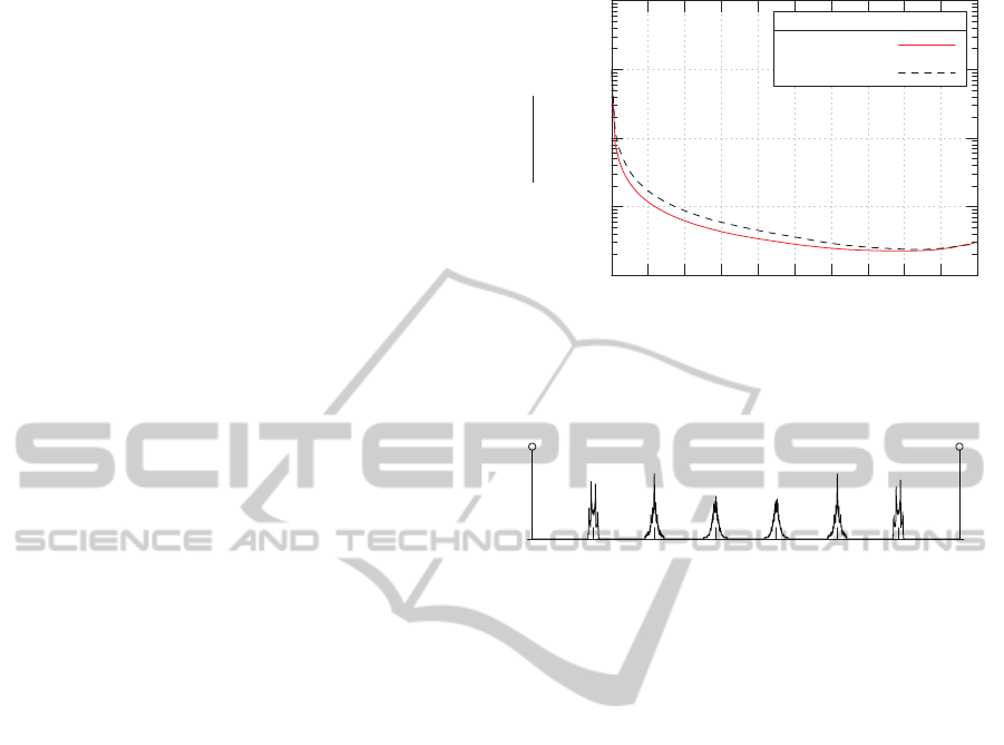
picted in Figure 1 for both variants of the algorithm.
In the random case, the error is smaller than 1% for
97% of the full scale value range and by sorting a fur-
ther improvement can be achieved. Since the ampli-
tude error is a-priori known at the transmitter and, as
shown, very small for a typical office room scenario,
it can be neglected in most cases.
To create EQSAM with receive power values
close to an ASK constellation, it is essential to place
the LEDs close together and in sufficient distance
from the receiver, such that their angles and distances
to the detector are virtually equal. To evaluate the
amplitude accuracy, the probability distribution of an
8 − EQSAM constellation is exemplarily shown in
10
−4
10
−3
10
−2
10
−1
10
0
|d
m
−a
USAM
m
|
d
m
d
m
Variants
Descending
Random
Figure 1: Proportional error of the constellation constructed
Figure 1: Proportional error of the constellation constructed
with USAM in reference to the desired ASK constellation.
The error is an average of all positions in the room at desk
height. The number of reflections is limited to one.
a
EQSAM
m
Figure 2: Probability distribution of the EQSAM constella-
Figure 2: Probability distribution of the EQSAM constella-
tion at desk height.
Figure 2. It can be observed that the preciseness is
sufficient, when compared to the other relevant noise
sources. Changes in the environment, such as persons
moving in the room, are of similar influence on all
LED light paths and in consequence scale the constel-
lation, but are of negligible influence on the individual
constellation points.
Since the contribution of GEOSAM compared
to EQSAM lies in reducing the amount of required
switching elements while maintaining the geometric
LED arrangement, similar results concerning the con-
stellation accuracy can be expected.
4.3 Error Rate Performance
Assuming error free constellation amplitudes, justi-
fied in the last section, one can generate arbitrary pos-
itive and real-valued waveforms at the receiver. How-
ever, for a simple performance evaluation we will re-
strict ourselves in the following to generate ASK con-
stellations and calculate the SER for this special case.
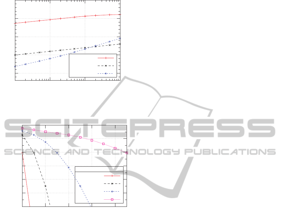
Comparing the different noise sources in Fig-
ure 3, one can identify ISI to be the dominating
noise source. Consequently, increasing the num-
ber of constellation points, while keeping the data
rate unchanged greatly reduces the SER, as shown in
Figure 4. E.g. for a SER of 10
−4
the data rate can be
OPTICS2015-InternationalConferenceonOpticalCommunicationSystems
32
10
−20
10
−15
10
−10
10
−5
10
0
1MHz 10MHz 100MHz 1GHz
f
σ
2
ISI
σ
2
shot
σ
2
therm
Figure 3: Noise sources at different symbol rates using
Figure 3: Noise sources at different symbol rates using
OOK at detector position (0.3m,2.1m) .
10
−12
10
−10
10
−8
10
−6
10
−4
10
−2
10
0
2 8 32 128 512
SER
M
R
75 Mbit
150 Mbit
300 Mbit
750 Mbit
Figure 4: SER of EQSAM for an detector at position
Figure 4: SER of EQSAM for an detector at position
(0.3m,2.1m).
increased by the factor of 10 using 1024− EQSAM
instead of OOK. Likewise the thermal noise and the
shot noise occurring in the receive amplifier circuitry
depend on the switching speed. This can be explained
by the increased bandwidth requirements on the re-
ceive amplifier.
4.4 Peak to Average Power Ratio
When applying the SAM switching schema on an
LED cluster, it is favorable, in terms of operating
efficiency, to fully exploit the LEDs maximal lumi-
nous output power. This is ensured, if the modulation
method’s PAPR does not exceed the LED’s peak to
average current limit.
With equal distributed input sequences, the PAPR
is two for GEOSAM and EQSAM. While an ho-
mogeneous distribution of the switching pattern for
the individual LEDs is inherently given when using
GEOSAM, it has to be ensured for EQSAM, e.g. by
rotating the LED assignment for every send symbol.
The PAPR of USAM using the sorting variant of
the algorithm is converging to three for the given sim-
ulation setup, e.g. the remaining error is smaller than
6% for M
USAM
= 8, but some LEDs are switched on
more frequently.
An uniformdistribution of the LED usage evolves,
if the algorithm’s randomized variant is applied for
each modulation symbol independently. This variant
has a PAPR of approximately two.
5 MEASUREMENTS RESULTS
To justify the assumption of quasi-equal channel co-
efficients in the case of EQSAM and random distri-
bution in the case of USAM we have measured the
receive power values for seven LEDs positioned on
a ring of 5cm radius, similar to the simulation setup
for EQSAM and GEOSAM. The distance between
the light sources and the receiver was set to 20cm and
100cm respectively. For a distance of 20cm the re-
ceive values are
[0.392, 0.468, 0.521, 0.476, 0.421, 0.370, 0.360]
and
[0.0570, 0.0581, 0.0553,0.0550,
0.0559, 0.0513, 0.0520]
for a distance of 100cm.
It can be observed that the normalized receive
value variance is decreasing from 0.019 to 0.0021
with the distance increasing from 20cm to 100cm,
that is why we can assume quasi-equal receive val-
ues for a typical indoor VLC ceiling light. On the
other hand, USAM can be used favorably in cases
with varying receive values, e.g. the light sources
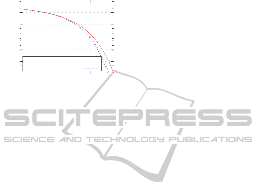
are distributed on the ceiling of a room. Figure 5
displays the influence of the measured receive power
values on the BER of EQSAM, assuming a pure addi-
tive white Gaussian noise channel model. The results
show a marginal loss of about 0.1dB for 1m distance
between the receiver and the LED light sources at a
BER of 10
−5
.
6 COMPARISON OF SAM TO
ALTERNATIVE
INTENSITY-MODULATION
TECHNIQUES
An alternative to switching the LEDs completely off
is to modulate the binary OOK signal on a DC car-
rier. Such data transmission systems are proposed in
AmplitudeModulationbySuperpositionofIndependentLightSources
33
10
−6
10
−5
10
−4
10
−3
10
−2
10
−1
10
0
10 15 20 25 30
BER
E
S
/N
0
in dB
20 cm distance
100 cm distance
Equal receive powers
Figure 5: BER of EQSAM with measured receive power
Figure 5: BER of EQSAM with measured receive power
values.
(Minh et al., 2009) for a data rate of 100
MBit
/s with
a modulation depth 0.6 and in (Vuˇci´c et al., 2010a)
for 230
MBit
/s data rate with a modulation depth of
0.03/0.06. With this method the data rates can be
increased significantly, at the same time reducing the
SNR by introducing a carrier signal. This method can
be combined with SAM, resulting in an ASK modu-
lated signal plus constant offset at the receiver.
Another alternative for high speed VLC commu-
nication is intensity-modulated DMT signaling, like-
wise requiring an DC bias. Examples are (Vuˇci´c et al.,
2010b) with a data rate of 513
MBit
/s and a modulation
depth of 0.13, (Cossu et al., 2012) with a data rate of
1.5
GBit
/s per LED color and (Tsonev et al., 2014) with
a data rate of 3
GBit
/s. In the following these alterna-
tives are compared to the proposed SAM schemes re-
garding the hardware effort, the calculation complex-
ity as well as concerning the achievable data rates.
6.1 Hardware Effort
Transmitter. For implementing the SAM transmit-
ter one can replicate a low-complexity OOK transmit
circuit for a number of LED lighting elements. In
our setup, we used two mosfets of type IRML2030,
one ISL55111 gate driver and six passive components
to construct a low-cost switching element that can be
operated with 40MHz switching speed in conjunction
with an Osram Ostar LED of type LE B Q8WP. For
higher switching speeds an additional DC-biasing is
often employed.
In contrast, the use of intensity-modulation tech-
niques like DMT typically require a high-speed
digital-to-analog converter, an linear amplifier circuit
and a DC-bias for driving the transmit LEDs. Thus,
the circuit complexity of SAM is significantly lower
than for intensity-modulated schemes like DMT.
Receiver. The typical receiver consists of a photo-
detector, a transimpedance-amplifier and an analog-
to-digital converter. In contrast to DMT systems,
ASK demodulation like used for SAM, can alterna-
tively be implemented using analog components for
detection.
6.2 Computational Complexity
The computational effort of SAM is low, since only a
mapping of the serial datastream to the transmit units
is required. Additionally, in case of USAM, the map-
ping rule is updated if the channel coefficient change.
For intensity modulation, compensation of the
LED characteristics (compare (Elgala et al., 2010))
is required, whereby the SAM method inherently su-
perimposes the amplitudes to an intensity-modulated
signal without introducing distortions.
6.3 Achievable Data Rates
Using SAM, the data rates increase with the num-
ber of individually switchable lighting elements. For
example, the 230
MBit
/s OOK setup in (Vuˇci´c et al.,
2010a) could be combined with an 32-SAM approach
to obtain a data rate of 1150
MBit
/s. This would require
the use of 5 (GEOSAM), 8 (USAM) or 31 (EQSAM)
LEDs. Comparable rates can be obtained with DMT,
for example using a single intensity-modulated LED.
7 CONCLUSION AND OUTLOOK
We introduced a novel method for generating arbi-
trary receive waveforms by digitally switching indi-
vidual LEDs, dubbed SAM. With this method the
data rate of OOK VLC systems can be increased with-
out the need for intensity-modulation of individual
LEDs. In particular, this allows to generate an ampli-
tude modulated LED light source with a modulation
depth of one.
Increasing the data rate while maintaining the
LED switching speed is one possibility for the devel-
opment of high speed VLC systems offered by SAM.
One reason is the junction capacity of the LEDs as
limiting physical parameter. The advantages of using
SAM are even more significant, when phosphoric ma-
terials or organic LEDs are used, that further limit the
possible signal bandwidth.
On the other hand, given a data rate requirement,
we are able to reduce the symbol rate and therewith
ISI. This leads not only to increased SNR values, but
also the employed equalization algorithms can be, if
OPTICS2015-InternationalConferenceonOpticalCommunicationSystems
34

not removed completely, at least reduced in complex-
ity.
One open question is the implication on the con-
stellation accuracy in time-varying environments. A
next step could also be to use the new SAM methods
in combination with modulation schemes like DMT.
The channel coefficients, obtained by the receiver
can be used additionally for positioning and localiza-
tion purposes.
REFERENCES
Cossu, G., Khalid, A. M., Choudhury, P., Corsini, R., and
Ciaramella, E. (2012). 3.4 Gbit/s visible optical wire-
less transmission based on RGB LED. Optics Express,
20(26):B501–B506.
Elgala, H., Mesleh, R., and Haas, H. (2010). An LED
model for intensity-modulated optical communica-
tion systems. IEEE Photonics Technology Letters,
22(11):835–837.
Komine, T., Lee, J., Haruyama, S., and Nakagawa, M.
(2009). Adaptive equalization system for visible light
wireless communication utilizing multiple white LED
lighting equipment. IEEE Transactions on Wireless
Communications, 8(6):2892–2900.
Li, J. F., Huang, Z. T., Zhang, R. Q., Zeng, F. X., Jiang,
M., and Ji, Y. F. (2013). Superposed pulse amplitude
modulation for visible light communication. Optics
Express, 21(25):31006–31011.
Minh, H. L., O’Brien, D., Faulkner, G., Zeng, L., Lee, K.,
Jung, D., Oh, Y., and Won, E. T. (2009). 100-Mb/s
NRZ visible light communications using a postequal-
ized white LED. IEEE Photonics Technology Letters,
21(15):1063–1065.
O’brien, D., Zeng, L., Le-Minh, H., Faulkner, G.,
Walewski, J., and Randel, S. (2008). Visible light
communications: Challenges and possibilities. In
IEEE 19th International Symposium on Personal,
Indoor and Mobile Radio Communications, 2008.,
pages 1–5.
Tsonev, D., Chun, H., Rajbhandari, S., McKendry, J., Videv,
S., Gu, E., Haji, M., Watson, S., Kelly, A., Faulkner,
G., Dawson, M., Haas, H., and O’Brien, D. (2014). A
3-Gb/s single-LED OFDM-based wireless VLC link
using a gallium nitride µLED. IEEE Photonics Tech-
nology Letters, 26(7):637–640.
Vuˇci´c, J., Kottke, C., Nerreter, S., Habel, K., Buttner,
A., Langer, K.-D., and Walewski, J. (2010a). 230
Mbit/s via a wireless visible-light link based on OOK
modulation of phosphorescent white LEDs. In Opti-
cal Fiber Communication (OFC), collocated National
Fiber Optic Engineers Conference, 2010, pages 1–3.
Vuˇci´c, J., Kottke, C., Nerreter, S., Langer, K.-D., and
Walewski, J. W. (2010b). 513 Mbit/s visible light
communications link based on DMT-modulation of
a white LED. Journal of Lightwave Technology,
28(24):3512–3518.
AmplitudeModulationbySuperpositionofIndependentLightSources
35
