
Novel Progress in the High-sensitivity Heterolithic Ring Laser Gyroscope
Technology
R. Santagata
1,2
, J. Belfi
2
, N. Beverini
2,3
, G. Carelli
2,3
, A. Di Virgilio
2
, E. Maccioni
2,3
and A. Simonelli
2,3,4
1
Department of Physics, University of Siena, Via Roma 56, Siena, Italy
2
INFN Section of Pisa, Largo Bruno Pontecorvo 3, Pisa, Italy
3
Department of Physics, University of Pisa, Largo Bruno Pontecorvo 3, Pisa, Italy
4
Department of Earth Sciences, University of Pisa, Via Santa Maria 53, Pisa, Italy
1 ABSTRACT
The sensitivity achieved by large ring laser gyro-
scopes opens the perspective to observe in an Earth-
located laboratory extremely small effects expected
from fundamental theories of physics. The next-
generation sensor that could provide the required ac-
curacy is a multiaxial heterolithic ring laser actively
stabilized via a precise external diagnostic of circu-
lating laser beams path.
Here we report about the research activities and
recent progress toward the development of a large
frame He-Ne triaxial sensor with an ultimate accu-
racy of 10
−11
, in order to detect the relativistic Lense-
Thirring effect related to the Earth rotating mass. The
actual activity is focused on the control of the sys-
tematic errors related to the fluctuation of the cavity
geometry and the laser active medium parameters. In
this work we will discuss in details only the first issue,
to which my PhD studies are mainly dedicated.
2 RESEARCH PROBLEM AND
OUTLINE OF OBJECTIVES
Ring lasers gyroscopes (RL) are inertial sensors
able to measure absolute rotations (Stedman G.E.,
1997); if they are placed at rest in a ground-located
laboratory, the measured rotation is that of our planet
~
Ω
⊕
.
Lense-Thirring effect, predicted by Einstein’s Theory
of General Relativity, consists in a dragging of
the local inertial frame of reference caused by the
perturbation of the local metrics in the proximity
of a spinning massive body like Earth (Lense J.
and Thirring H., 1918). This implies that the Earth
rotation rate measured against the ”fixed-stars”
inertial frame differs from the rotation rate measured
in the laboratory frame. In the low field approxi-
mation, the dominant correction terms are given by
a geodetic term (or gravito-electric effect) due to
the gravitational red-shift, and by a dragging term
proportional to the angular momentum, known as
Lense-Thirring effect or gravito-magnetic effect. On
the Earth surface both corrective effects are of the
order of 1 part in 10
9
of
~
Ω
⊕
, but while the geodetic
term is radially directed, the dragging one has a
dipolar shape.
This has been already observed as global effect on
orbiting satellites, as GRAVITY-B experiment and
LAGEOS orbital data analysis (Everitt C.W.F. et al.,
2011) (Ciufolini I., 1986). The experiment named
GINGER (Gyroscopes IN GEneral Relativity) (Bosi
F. et al., 2011) (Di Virgilio A. et al., 2014) aims
at measuring, for the first time in a ground-based
laboratory, the Lense-Thirring effect locally, by
using an array of large RLs placed in a Earth-based
laboratory.
The requirements needed to make this possible
can be clearly understood examining the sensor re-
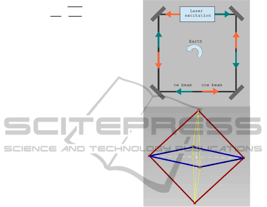
sponse. The basic setup of a RL is made up of a sta-
ble ring optical cavity along which an active medium,
typically a He-Ne mixture, is placed (figure 1); two
laser beams are generated and propagate in opposite
directions along the loop. A Sagnac beat frequency of
the circulating beams is measured (Sagnac G., 1913):
f
S
=
4
~
A·
~
Ω
λP
, (1)
where
~
Ω =
~
Ω
⊕
+
~
Ω
′
is the rotation relative to the local
Lorentz inertial frame (being Ω
′
any correction term),
~
A is the area vector enclosed by the ring optical path
P and λ is the wavelength of the laser.
The sensitivity limit of a RL is given by the shot-
noise:
10
Santagata R., Jacopo J., Beverini N., Carelli G., Di Virgilio A., Maccioni E. and Simonelli A..
Novel Progress in the High-sensitivity Heterolithic Ring Laser Gyroscope Technology.
Copyright
c
2015 SCITEPRESS (Science and Technology Publications, Lda.)
Ω
sn
=
vP
4AQ
s
hf
P
out
T
, (2)
where v is the velocity of the laser beam along the
cavity, Q is the quality factor of the resonator, h the
Planck constant, P
out
the detected optical power and
T the measuring time.
From equation 1 two important features follow:
the dependence of Sagnac frequency f
S
on the laser
path geometry via the scale factor k
S
= 4A/λP, and
the scalar nature of the sensor output, being measured
only the projection of the velocity vector
~
Ω on the
enclosed area
~
A.
The development of a high sensitivity RL requires:
• a large frame structure. To increase the size of the
ring cavity, in fact, implies to increase the signal
to noise ratio (SNR), being the signal proportional
to the ratio A/P via the scale factor, and the shot
noise of the sensor proportional to P via the qual-
ity factor Q.
• a high-Q resonator (> 10
11
and higher). Low-loss
’five-9s quality’ supermirrors must be used.
• a multi-axial system of RL, in order to recon-
struct the modulus of the Earth rotational vec-
tor and compare the Earth rotation rate measured
locally with the one provided by IERS (Interna-
tional Earth Rotation and Reference Systems Ser-
vice). Otherwise, an absolute calibration of the
RL orientation at a level of 0.1 nrad would be
needed.
• to reduce the instrumental drift in the measure-
ment of rotation rate to less than Ω
′
/Ω
⊕
. This
needs a long-term strict control on the fluctuation
of laser active medium, cavity geometry and, in a
RLs array, of relative dihedral angles.
• to reduce all the sources of Earth-surface and en-
vironmental noise, installing the detector in a very
stable geological environment, well coupled to the
solid rock, in a low environmental noise labora-
tory, possibly located underground.
3 STATE OF THE ART
To this day, the best RL is the Grossring ’G’, lo-
cated at the Geodatisches Observatorium in Wettzell,
Bavaria (Schreiber K.U. et al., 2009) (Schreiber K.U.
et al., 2011). It has achieved a resolution better than
5× 10
−13
rad/s with an integration time of few hours,
becoming of geodetic interest for measuring short-
term fluctuation, with periods of hours to days, in
Earth rotation.
Figure 1: Ring laser gyroscope. Above: setup of a square
RL. Below: triaxial sensor made of 6 mirrors. Each couple
of opposite mirrors is shared between two rings.
This stability record is mainly due to its building
material that allows a strong passive stabilization of
the optical cavity. G, in fact, is a semi-monolithic de-
vice made in Zerodur, a glass ceramic with an espe-
cially small thermal expansion, high mechanical sta-
bility and consistency of shape and length. Four bars
are rigidly connectedto a base plate forming the edges
of a square 4 m length in side; spherical supermirrors
are attached to the face sides of the bars by molecu-
lar adhesion, ensuring a stable vacuum seal. It is kept
in an underground controlled room and equipped with
an active control of the cavity perimeter that stabilizes
the circulating laser beams frequency against an opti-
cal frequency reference.
Albeit G resolution is very close to that required
to detect the relativistic effects on rotation, its design
can’t be used to develope a large frame RLs array,
since larger monolithic blocks of Zerodur are not
available. The next-generation RL able to detect tiny
effects, as Lense-Thirring effect, has a heterolitic
NovelProgressintheHigh-sensitivityHeterolithicRingLaserGyroscopeTechnology
11

multi-axial design equipped with a precise diagnostic
system of laser beam path deformation, in order to
stabilize the scale factor k
S
better than 10
−10
.
Recent studies and experimental activities made in
this context on the middle-size heterolitic RL ’G-Pisa’
(Belfi J. et al., 2012), have motivate the design of the
GINGER device. It consists in a triaxial system of
large square heterolitic RLs arranged in a octahedral
structure (figure 1). A suitable location for this device
could be the underground facility of LNGS (Labora-
tori Nazionali del Gran Sasso - Italy).
To accomplish GINGER’s goal needs a control of the
systematic errors related to the fluctuation of the cav-
ity geometry and the laser active medium parameters.
As regards the last issue, a set of spectroscopic di-
agnostic of the active medium parameters and an off-
line denoising method that, based on the Kalman filter
approach, subtracts from the raw Sagnac data the sys-
tematic effects induced by the non-linearity of the RL
dynamics, has been developed (Beghi A. et al., 2012)
(Cuccato D. et al., 2014). In the following, we’ll dis-
cuss mainly about the first research field.
4 RING CAVITY GEOMETRY
CONTROL
The measure of Lense-Thirring effect in a ground-
based laboratory requires a stabilization of the scale
factor k
S
better than 10
−10
. This implies an accuracy
on mirror positions better than 1 nm and on the ring
cavities relative orientation better than 1 nrad.
In a square RL, a so strict control on mirror posi-
tions can be reduced if the absolute length of the diag-
onal cavities is stabilized in addition to the perimeter
one, so that the closed optical path shape is that of a
regular square. Our theoretical and numerical stud-
ies are reported in detail in Ref.(Santagata R. et al.,
2014). We showed that if the length of the two diago-
nals are locked to the same value, the perturbations to
the mirror positions affect only quadratically the ring
laser scale factor. This constraint reduces the mirror
position fluctuation at a level of 1 part in 10
10
, even if
the two lengths are stabilized to values that differs at
a micrometric scale.
These results motivated the design of GP2 (Di
Virgilio A. et al., 2014), an intermediate prototype
of GINGER specifically devoted to test the active
control strategies and, in particular, to implement
the length stabilization of the diagonal resonators by
means of optical interferometry. In addition to it, the
GINGERino prototype has also been developed last
year (Di Virgilio A. et al., 2014); it is especially birth
to analyze the seismic noise at LNGS location, but
also to tryout the SNR improvement of a larger cav-
ity.
The optical setup of both devices consists in four
supermirrors each one contained in a steel holder
placed at the corner of a granite support fixed on a
concrete base. Steel pipes connected by the mirror
holders define the vacuum chamber that encloses the
optical path of the circulating beams along a square
loop. The vacuum chamber is filled with a mixture of
He-Ne and the capacitive discharge for laser excita-
tion, consisting in a pyrex capillary, is located in the
middle of a side of the cavity. The laser frequency is
stabilized with respect an optical frequency reference
in order to actively control the ring cavity perimeter.
In section 5 GP2 and GINGERino prototype are
described. To stabilize the absolute length of di-
agonal resonators we worked out an interferometric
metrology technique and we tested it on two Fabry-
Perot cavities simulating the ring diagonals on an op-
tical bench. We report some details about this work,
whose results has been published in Ref.(Belfi J. et
al., 2014), in section 6. Finally, in section 7 expected
outcome and future perspectives are discussed.
5 METHODOLOGY
5.1 GP2
5.1.1 Optical Setup
GP2 is the seed device for the next generation het-
erolitic active-stabilized RLs. It has been designed in
order to gain a long term stability and accuracy of the
scale factor, via a precise control of the systematic er-
rors related to the fluctuation of the cavity geometry
and the active medium parameters. In particular, it is
dedicated to implement a length stabilization of the
diagonal cavities using optical interferometric tech-
niques.
Figure 2 shows a drawing of GP2 (above) and its
installation in a clean room at INFN Pisa laboratories
in March 2014 (below). The granite slab whereon the
cavity is placed is oriented along the local latitude in
order to maximize the Sagnac signal and minimize
the orientation errors on scale factor. The four mir-
rors holders are placed at the corner of a square gran-
ite slab and the vacuum chamber encloses the beam
optical path along a square loop 1.60 m length in
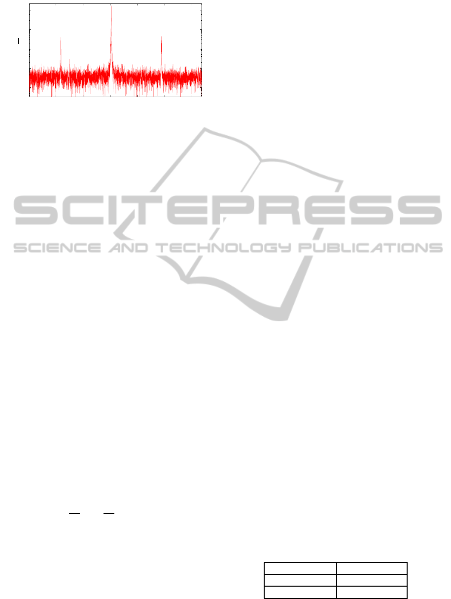
side. Figure 3 shows a preliminary Sagnac spectrum;
a Sagnac frequency of 184 Hz has been observed, as
expected.
To check the quality factor Q = 2π fτ of the laser
PHOTOPTICS2015-DoctoralConsortium
12
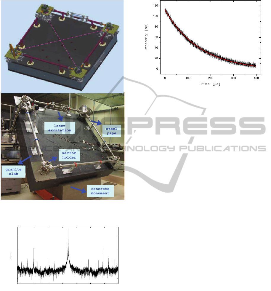
Figure 2: GP2 ring laser gyroscope. Above: drawing of the
design. Below: The sensor installed at the clean room of
INFN Pisa section laboratory (March 2014).
150 160 170 180 190 200 210
10
−8
10
−6
10
−4
10
−2
Frequency (Hz)
PSD
V
√
H z
Figure 3: Power spectral density of GP2 data. The Sagnac
response peak at 184 Hz is observed.
cavity we made a ring-down time τ measurement
of the laser by short-circuiting the discharge capac-
itor. In figure 4 we report the laser intensity decay
trace acquired by the oscilloscope. Fitting to data
the exponential function I = I
0
+ Ce
−t/τ
, where I
0
is the initial intensity and C a numerical constant,
we have obtained a measure for the ring-down time
τ = 154.4± 0.5 µs. This corresponds to a quality cav-
ity factor Q = 4.6 × 10
11
Figure 4: Ring-down time measurement of GP2 laser cavity.
Black line: trace of laser intensity decay acquired by the
oscilloscope. Red line: exponential fit of data points. Fit
results: τ = 154.4 ± 0.5 µs; I
0
= −3.35 ± 0.10 mV; C =
114.63± 0.14 mV.
5.1.2 Mechanical Expedients for Diagonal
Cavities Stabilization
The slab whereon the holders are mounted is made of
precise black granite, a rock well suited for metrology
application for his long term thermal and dimensional
stability, high flatness accuracy, high bending strength
and insensitivity to mechanical overloading. It has
been machined with a precision better than 10 µm to
guarantee a preliminary well positioning of the corner
mirrors.
To implement the diagonal absolute length sta-
bilization, by using the experimental technique de-
scribed in section 6, the GP2 vacuum chamber has
been designed in order to give access to the diagonal
resonators by enclosing the path of two external laser
beams along these, as well as the perimeter path of
the counter-propagating beams. These two additional
chamber parts, schematically indicated in the above
of figure 2, will be installed in the near future.
A high finesse of the Fabry-Perot cavities is guar-
anteed by a special mirror coating that ensures a re-
flectivity of about 99.9% at normal incidence, in ad-
dition to a reflectivity > 99.999% at 45 deg angle of
incidence.
The design of mirror holders, whose most impor-
tant features are showed in figure 5, is of key impor-
tance in view of the diagonal cavities use.
The mirrors are accessible through big optical
transparent windows installed parallel to them on
the holders. The window allows the circulating
monobeams to exit the cavity and to be monitored;
an external optical setup detects the beat frequency. In
addition, it consents to an external He-Ne laser source
hitting it at normal incidence to enters into the diago-
nal resonators, as showed in the below of figure 5.
NovelProgressintheHigh-sensitivityHeterolithicRingLaserGyroscopeTechnology
13
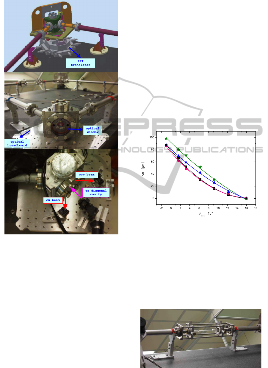
Figure 5: GP2 Mirror holders. Above: drawing of the
holder design; the piezo system is shown. Middle: picture
of the holders installed on the granite slab. The big optical
transparent window allowing the optical access to corner
mirror is shown. Below: detail of holder. The optical setup
needed to combine the circulating beams is also shown. The
combiner is mounted on a small breadboard and consists in
two high-reflection dielectric mirrors 0.5 inch in size. For
the detection of the beat frequency, a photodiode integrated
with an interference filter is used. The three allowed di-
rections (monobeams exiting the cavity and external laser
source entering in the diagonal resonator) are pointed out.
To get a regular square cavity by a dynamic con-
trol, the mirror holders are equipped with a piezo
nano-positioning system. Since each mirror displace-
ment can be described as a variation in the space of the
position of its curvature center, the geometry of the
optical path along the square loop is completely de-
termined by the 12 centres coordinates (12 degree of
freedom). In Ref.(Santagata R. et al., 2014) we have
defined the eigenvectors basis of the cavity deforma-
tions, identified the rigid body motion of the cavity,
and then classified the residual 6 optical cavity defor-
mations once the diagonal lengths are stabilized. For
this reason, in GP2 a total of 6 piezo-electric trans-
ducers (PZT) is used. One holder is provided with a
3-axial PZT, while the other three with a 1-axial PZT
along the diagonal.
The piezo system has a dynamic range of 80 µm.
To have an estimate of the displacement response, we
made a calibration of the 1-axial translators by mea-
suring the displacement induced by an applied volt-
age. The PZT calibration data are plotted in figure
6; a second order polynomial fit provide a displace-
ment constant mean value of (7.4 ± 0.6) µmV
−1
for
the mirrors mounted on the north side of the RL, and
(9.2 ± 0.4) µmV
−1
for the mirrors mounted on the
south side.
Figure 6: PZT calibration data. The displacement data
induced by an applied voltage are plotted for each 1-
axial piezo moving the mirror holder along the ring cav-
ity diagonal. Positive variation means displacement to-
ward the center of the ring. A second order polynomial
∆x = AV
PZT
+ BV
2
PZT
is fitted to data. From top to bot-
tom: corner 4 (green line), A
1
= (−9.3 ± 0.2) µmV
−1
,
B
1
= (0.271 ± 0.013) µmV
−2
; corner 3 (blue line), A
2
=
(−9.0± 0.3) µmV
−1
, B
2
= (0.269 ± 0.018) µmV
−2
; cor-
ner 1 (black line), A
3
= (−7.2±0.3) µmV
−1
, B
3
= (0.132±
0.017) µmV
−2
; corner 2 (magenta line), A
4
= (−7.5 ±
0.5) µmV
−1
, B
4
= (0.10± 0.04) µmV
−2
.
Figure 7: Pyrex tube for the excitation of the He-Ne plasma.
PHOTOPTICS2015-DoctoralConsortium
14
A fine control of the laser beam path requires also
a well positioning of the discharge system. To this
aim, the pyrex capillary is linked to the steel pipes by
means of a cage system equipped with a micrometric
regulation of its position and tilt. A detail of the cage
system is reported in figure 7.
5.2 GINGERino
GINGERino is an evolution of G-Pisa RL. While the
fundamental purpose of G-Pisa was to acquire the ex-
pertise on the operation of a large frame RL, GIN-
GERino is its upgrading that has been placed in the
LNGS underground laboratory in order to test the ad-
equacy of the site to guest the GINGER apparatus.
The 1400 m thick rock of the central massif of
Gran Sasso constitutes a natural shielding against all
the sources of noise coming from the surface activi-
ties. The underground environment guarantees in ad-
dition a high stability of the local environmental pa-
rameter such as pressure, temperature and humidity.
At the same time, the operation of GINGERino in
a low local noise laboratory could give the possibil-
ity to detect geodetic signals (Polar motion, Chan-
dler wobble, tidal effects,...) and seismic signals (S-
wave phase velocity,...) for which a sensitivity of
10
−9
− 10
−13
rad/s is sufficient. The analysis of the
rotational seismic noise and its correlation with clas-
sical seismometer signals will be carried out by re-
searchers of INGV (Italian National Institute of Geo-
physics and Vulcanology). A comparison with G
measurements would be very interesting in the case
of non-local effects, such as tele-seismic events.
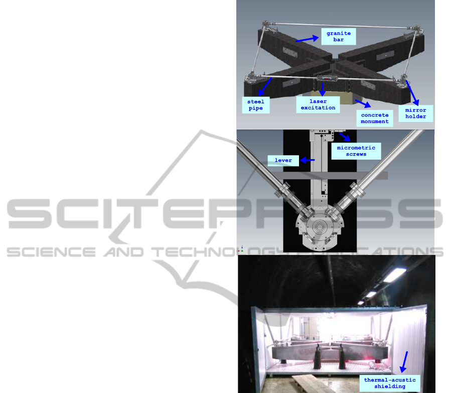
Figure 8 shows a drawing of GINGERino (above)
and its installation in the Node A of the so-called ”in-
terferometric tunnel” at LNGS in October 2014 (be-
low). This gallery is in the northern part of the labo-
ratories, away from the 3 large Halls hosting the main
experiments and so away from the principle sources
of daily human activity noise. As in GP2, the square
optical cavity consists in supermirrors placed inside
corner holders connected by steel pipes. Holders
and pipes are those of the first prototype, G-Pisa, in-
creased in size to get a length of side of 3.60 m. A
Sagnac frequency of 280 Hz has been observed, as
shown in figure 9.
The cavity is mounted on a granite slab installed
on a concrete monument well connected to the rock
floor. To reduce the weight of the apparatus and sim-
plify its installation in the cave, the slab consists in
four arms that has been inserted in loco into a central
square granite block. To improve the mechanical sta-
bility of the discharge system, the capillary holder is
fixed on a breadboard sustained by four concrete pil-
Figure 8: GINGERino ring laser gyroscope. Above: draw-
ing of the design. Middle: detail of the lever system con-
trolled by micrometric screws used to align the ring cavity.
Below: installation at LNGS underground facility (October
2014). The thermal-acustic shielding enclosing it is shown.
lar; two of these sustain each cavity side also. The
mirrors, rigidly connected to the holders, can be tilted
to align the cavity by means of levers controlled by
micrometric screws (figure 8). Only two of the four
mirrors are equipped with a monodimensional micro-
metric PZT that, mounted under the holders, movethe
mirror along one diagonal of the square cavity. This
makes possible only a dynamic control of the beam
path perimeter, that is keep constant against an opti-
cal frequency standard.
The apparatus is enclosed by a thermal-acustic
shielding and the laboratory is warm up making
use of heat lamps simmetrically arranged around the
device. To give an assessment about the room-
temperature stability and homogeneity, we attached a
NovelProgressintheHigh-sensitivityHeterolithicRingLaserGyroscopeTechnology
15
240 260 280 300 320 340
10
−13
10
−12
10
−11
10
−10
10
−9
PSD
V
√
H z
Frequency (Hz)
Figure 9: Power spectral density of GINGERino data. The
Sagnac response peak at 280.05 Hz is observed.
platinum RTD (Resistance Temperature Device) sen-
sor attached to each corner of the steel cavity struc-
ture. Throughout 5 days, a maximum gradient of
0.5
◦
C between the mean values of temperature in two
different corners is observed; the fluctuation around
each mean value, measured using standard deviation,
is of 0.04
◦
C.
6 STAGE OF THE RESEARCH.
ABSOLUTE LENGTH
STABILIZATION OF THE
SQUARE RL DIAGONAL
CAVITIES
6.1 Measurement Principle
To stabilize the absolute length of a square RL di-
agonal resonators with respect to an interrogating
high-stability laser we worked out an interferometric
metrology technique and we tested it on two Fabry-
Perot cavities simulating the ring diagonals on an op-
tical bench. The technique we used is based on an
accurate frequency measurement of the resonant lon-
gitudinal mode and an univocal determination of the
interference order (Belfi J. et al., 2014). For a TEM00
laser mode of order n resonating in a cavity formed
by two concave spherical mirrors of radius R, the res-
onance frequency f
n
is given by:
f
n
=
v
2L
n+
1
2π
(Ψ
R
+ Φ
n
)
(3)
where v is the speed of light inside the cavity and L
is the distance between the mirrors. Ψ
R
and Φ
n
are
two phase corrections due respectively to the phase
accumulation along the direction of laser beam prop-
agation (Guoy phase) and the dielectric mirror phase
shift upon reflection; these two terms can be evaluated
from the knowledge of R and the mirror reflectivity
curve.
To measure L with a 10
−10
accuracy needs to mea-
sure f
n
with the same accuracy and define univocally
the integer n. This can be done locking the cavity
resonance to the laser carrier frequency (carrier lock)
and the phase modulation frequency to a harmonic m
of the free spectral range (sideband lock). We get the
two error signals required to implement the double-
lock modulating the laser source with a electro-optic
modulator (EOM) driven by three independent mod-
ulation frequencies: the first modulation at frequency
ω
A
provides the Pound-Drever-Hall signal for carrier
lock; the second modulation at frequency ω
B
provides
the lock-in amplifier error signal; the latter is referred
to a third modulation at ω
C
for shifting the the FSR
detection down to few tens kHz.
6.2 Apparatus and Experimental
Procedure
The apparatus we developed is shown in figure 10.
The laser source is a 10mW diode laser emitting at
633 nm. A high spectral purity is gained referring
it to an optical reference frequency provided by a
100 µW He-Ne laser frequency stabilized on the sat-
urated absorption line R-127 11-5 of Iodine. This
is achieved implementing a light amplifier based on
injection-locking. The features of the laser source are
summarized in table 1.
The Fabry-Perot resonators simulate the ring cav-
ity diagonals on an optical bench. They are formed
by curved mirrors mounted on holders connected by
Invar spacers; the output mirror is equipped with
a piezoelectric translator to implement the feedback
correction to the cavity length. The parameters of the
two resonators are reported in table 2.
The injection-locked laser beam, after being
triple-phase-modulated by a single fiber-coupled
EOM, enters into the two Fabry-Perot cavities. The
reflected beam, detected by a photodiode and splitted
by a two way power divider, is demodulated accord-
ing to a standard Pound-Drever-Hall scheme (first one
way) and by a digital lock-in amplifier (second one
way) in order to recover the carrier error signal ε
0
and
sideband error signal ε
S(1,2)
. These are used to apply
corrections to the cavity PZTs and to a Voltage Con-
trolled Oscillator (VCO) generating the sidebands at
m· FSR.
Table 1: Injection-locked laser source features.
Wavelength 633 nm
Output power 10 nW
Allan deviation 10
−11
(at100s)
The carrier feedback loop locks the two cavities
PHOTOPTICS2015-DoctoralConsortium
16
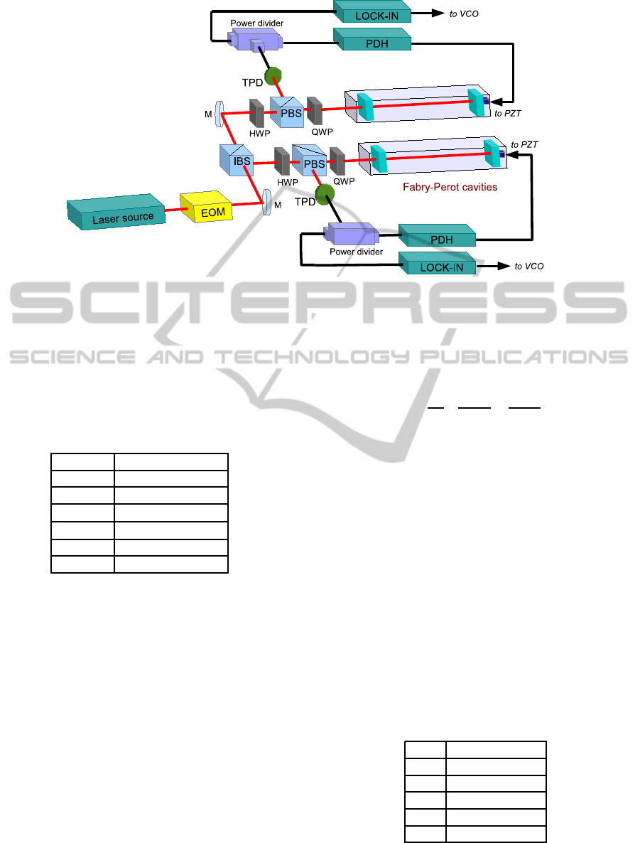
Figure 10: Conceptual scheme of experimental apparatus. A more detailed scheme is reported in (Belfi J. et al., 2014). The
laser source block represents the injection locking setup. The PDH stage represents the module for locking with Pound-Drever-
Hall scheme, while the Lock-in one includes the circuit for the digital lock-in amplifier phase-detection. EOM: Electro-Optic
Modulator. IBS: Intensity Beam Splitter. PBS: Polarizing Beam Splitter. HWP: Half Wave Plate. QWP: Quarter Wave Plate.
TPD: Transimpedance Photodiode. PZT: Piezoelectric Transducer. VCO: Voltage Controlled Oscillator.
Table 2: Optical parameters of cavities test-bench. They
have an identical mechanical setup, but the reflectivity of
the input mirror are different leading to different Full Width
at Half Maximum (FWHM) width of the resonator reso-
nances. Left: Cavity 1. Right: Cavity 2.
L 1.32 m
R 4 m
FSR 113 MHz
r
2
in
0.988; 0.997
r
2
out
0.999; 0.999
Finesse 480; 1570
FWHM 225 kHz; 54 kHz
resonance frequencies to the same laser carrier fre-
quency. The sideband feedback loop processes the
error signals ε
S(1,2)
by a LabView program running
on a PC and locks by turns the VCO frequency alter-
natively to m · FSR
1
or m · FSR
2
until the two inter-
ference orders n
1,2
= ω
0
/2π · FSR
1,2
are determined
with the required precision. A microwave frequency
counter connected to the auxiliary output of the VCO
acquires with a gate-time of 1 s the FSR
1,2
data.
6.3 Results
A gaussian fit of the FSR data provides an esti-
mate for the central frequency of the two cavities
f
c1
, f
c2
and the standard deviation about these
σ
1
, σ
2
. The frequency data are then used to cal-
culate the distribution of the mode number difference:
n
D
=
ω
0
2π
1
FSR
2
−
1
FSR
1
, (4)
whose standard deviation σn
D
is finally used to es-
timate the length difference δD = (λ/2) · σn
D
. The
mode difference n
D
should be an integer univocally
determined; in this case the error on the length differ-
ence between the two diagonals is ultimately limited
by the uncertainty on the laser wavelength.
Since the optical frequency is stabilized at the
level of 1 part in 10
11
, the uncertainty on the mode
number difference σn
D
is given by the uncertainty
∆FSR
i
/FSR
i
, i = 1,2. In table 1 we report the results
of the analysis of the frequency data acquired modu-
lating at ω
B
= 6 × FSR. The FSR mean values are
determined to few parts in 10
7
, and the correspond-
ing mode number difference with an uncertainty of
1.6. This is finally used to estimate the length differ-
ence δD = (λ/2) · σn
D
, that with our set-up is 500 nm
(Belfi J. et al., 2014). Note that the FSR uncertainty
Table 3: Experimental results of cavities test bench.
f
c1
681211560 Hz
σ
1
230 Hz
f
c2
680000798 Hz
σ
2
140 Hz
n
D
7427
σn
D
1.6
decreases as cavity finesse increases. We have studied
also the dependence of σ
i
on harmonic m, and our ex-
NovelProgressintheHigh-sensitivityHeterolithicRingLaserGyroscopeTechnology
17

perimental results suggest an improvementin FSR de-
termination as m
−1
. These considerations are of rele-
vance in view of the implementation of the technique
in GP2.
7 EXPECTED OUTCOME
The primary expected outcome of the future work is
to make the most of the developed expertise to run
GP2 with the target geometrical stability of 1 part in
10
10
. We intend to implement the length stabilization
of the GP2 diagonal cavities by using the experimen-
tal setup described in section 6 with some adaptions.
First, in the test bench experiment the laser source
was modulated by a single EOM and a single VCO
was alternatively locked to the resonances of the two
cavities. To ensures a long-term run of the RL with
the diagonal stabilization constraint, we plan to divide
the laser beam with a bifurcated fiber and to modulate
the resulting two beams by using two identical EOMs.
Moreover, we have to take into account that an un-
avoidable uncertainty on the measurement of the in-
stantaneous length of a cavity is the acoustic. Since
in a RL the mirror position actuators have a limited
bandwidth (< 100 Hz) due to mirror holders inertia,
a possible solution is to lock the laser to the diagonal
cavities using an acousto-optic modulator (AOM) that
compensatesthis noise by shifting the laser frequency.
The GP2 diagonal resonators have a FSR of
66 MHz and a finesse of ≃ 3000. In this case, operat-
ing with a modulation frequency ω
B
= 1 GHz (EOM
bandwidth cut-off) we expect to be able to determine
the mode number difference univocally, i.e. with an
uncertainty less than 1.
Furthermore, the full startup of GINGERino pro-
totype will test the adequacy of LNGS location in
terms of rotational noise and environmental stabil-
ity. From its operation we foresee an improvement
of SNR respect to G-Pisa of about a factor 7, be-
ing the increase in SNR more than quadratic with the
ring side size, as explained in section 2. In this case,
geodetic and microseismic signals will be detected,
and we plan to compare the acquired data with those
provided by G ring laser and by different rotational
seismology observatories.
If we achieve these results, the potentialities of an
heterolitic large RL for the detection of tiny effects, as
Lense-Thirring effect, will be experimentally demon-
strated, and a first important step toward GINGER
will be taken.
REFERENCES
Beghi A. et al. (2012). Compensation of the laser parameter
fluctuations in large ring-laser gyros: a Kalman filter
approach. Appl. Opt. 51, 7518-7528.
Belfi J. et al. (2012). A 1.82 m2 ring laser gyroscope for
nano-rotational motion sensing. Appl. Phys. B 106,
271-281.
Belfi J. et al. (2014). Interferometric length metrology for
the dimensional control of ultra-stable ring laser gyro-
scopes. Class. Quant. Grav. 31, 225003.
Bosi F. et al. (2011). Measuring Gravito-Magnetic Effects
by Multi Ring-Laser Gyroscope. Phys. Rev. D 84,
1220022.
Ciufolini I. (1986). Measurement of the Lense-Thirring
drag effect on LAGEOS and another high altitude
laser ranging satellite. Phys. Rev. Lett. 56, 278-281.
Cuccato D. et al. (2014). Controlling the non-linear in-
tracavity dynamics of large He-Ne laser gyroscopes.
Metrologia, 51, 97-107.
Di Virgilio A. et al. (2014). A ring lasers array for funda-
mental physics. Compt. rend. Phys. 15, 866-874.
Everitt C.W.F. et al. (2011). Gravity Probe B: Final Re-
sults of a Space Experiment to test General Relativity.
Phys. Rev. Lett. 106, 221101.
Lense J. and Thirring H. (1918). Uber den Einfluss der
Eigenrotation der Zentralkorper auf die Bewegung der
Planeten und Monde nach der Einsteinschen Gravita-
tions theorie. Phys. Z. 19, 156-163.
Sagnac G. (1913). L’ether lumineux demontre par l’effet du
vent relatif d’ether dans un interferometre en rotation
uniforme. Comp. Rend. 157, 708.
Santagata R. et al. (2014). Optimization of the geo-
metrical stability in square ring laser gyroscopes.
arXiv:1411.2585.
Schreiber K.U. et al. (2009). The Large Ring Laser G for
Continuous Earth Rotation Monitoring. Journal of
Pure and Applied Geophysics, 166 1485.
Schreiber K.U. et al. (2011). How to Detect the Chandler
and the Annual Wobble of the Earthwith a Large Ring
Laser Gyroscope. Phys. Rev. Lett. 107, 173904.
Stedman G.E. (1997). Ring-laser tests of fundamental
physics and geophysics. Rep. Prog. Phys. 60, 615-
688.
PHOTOPTICS2015-DoctoralConsortium
18
