
Towards a 3D Pipeline for Monitoring and Tracking People in an Indoor
Scenario using Multiple RGBD Sensors
Konstantinos Amplianitis, Michele Adduci and Ralf Reulke
Humboldt Universit
¨
at zu Berlin, Computer Science Department, Computer Vision Group,
Rudower Chaussee 25, 12489 Berlin, Germany
Keywords:
Calibration, Bundle Adjustment, 3D Object Extraction, Ellipsoid, 3D Human Tracking.
Abstract:
Human monitoring and tracking has been a prominent research area for many scientists around the globe.
Several algorithms have been introduced and improved over the years, eliminating false positives and en-
hancing monitoring quality. While the majority of approaches are restricted to the 2D and 2.5D domain, 3D
still remains an unexplored field. Microsoft Kinect is a low cost commodity sensor extensively used by the
industry and research community for several indoor applications. Within this framework, an accurate and fast-
to-implement pipeline is introduced working in two main directions: pure 3D foreground extraction of moving
people in the scene and interpretation of the human movement using an ellipsoid as a mathematical reference
model. The proposed work is part of an industrial transportation research project whose aim is to monitor the
behavior of people and make a distinction between normal and abnormal behaviors in public train wagons.
Ground truth was generated by the OpenNI human skeleton tracker and used for evaluating the performance
of the proposed method.
1 INTRODUCTION
Human detection and tracking has been a challenging
task for many scientists in the computer vision and
machine learning communities. Many researchers
have been thoroughly working in the direction of im-
proving and refining existing algorithms for achiev-
ing minimum detection failures. To the best of our
knowledge, the majority of these methods use train-
ing data for learning a classifier capable of detecting
and also labeling a human posture or action. Extend-
ing the problem in 3D, the work of (Munaro et al.,
2012), (Buys et al., 2014), (Sigalas et al., 2013) and
(Hegger et al., 2013) involved detecting people and
their body parts taking advantage of the richness of
the RGBD data. Nevertheless, these approaches seem
to deliver poor detection rates in environments with
lots of noise in the cloud, fast illumination changes
and overcrowding.
Interesting work was also introduced in the 3D
people tracking literature: the Unscented Kalman Fil-
ter (Ziegler et al., 2006) and the Random Hypersur-
face Models (Baum and Hanebeck, 2013) are some of
the most recent development techniques applied in the
area of human tracking in a cloud (Faion et al., 2012).
In a multi Kinect sensor configuration, the work of
(Faion et al., 2012) proposed a method for detecting
and tracking a person in the scene by fitting a cylinder
shape to its body.
For the specific application we are interested
in (surveillance in public train wagons), these ap-
proaches would fail for the following reasons:
• The Kinect network configuration in the wagon
covers only a limited field of view (FOV), intro-
ducing large amount of noise in the depth images
due to the conflict between the infrared emitters.
Thus, the generated point clouds contain a lot of
noise which in turn force the algorithms to fail
even after extensive tuning of the parameters.
• A train wagon consists of many non reflecting
areas such as windows, dark color seating, etc.
that significantly reduce the amount of data in the
point cloud. Areas in which the infrared light of
the sensor is absorbed by the element of the ob-
ject, returns no data to the depth image.
• Instant illumination changes (e.g. entering a sta-
tion platform from a dark tunnel) are some natural
environmental conditions that strongly affect the
quality of any detection algorithm.
• Rush hours in early morning and late afternoon
introduce a lot of occlusions and overlapping be-
192
Amplianitis K., Adduci M. and Reulke R..
Towards a 3D Pipeline for Monitoring and Tracking People in an Indoor Scenario using Multiple RGBD Sensors.
DOI: 10.5220/0005356601920200
In Proceedings of the 10th International Conference on Computer Vision Theory and Applications (VISAPP-2015), pages 192-200
ISBN: 978-989-758-091-8
Copyright
c
2015 SCITEPRESS (Science and Technology Publications, Lda.)

Algorithm 1: Extract the geometry of human motion.
Require: RGBD background and current cloud acquired by each sensor
1: Acquire RGBD data from all Kinect sensors in parallel
2: Trim point cloud in the depth direction using a pass-through filter
3: Extract moving foreground (Kammerl et al., 2012)
4: if foreground exists then
5: for all foregrounds do
6: Project foreground in a 2D plane
7: Extract closed contours (blobs) using connected components
8: if size of blob larger than a predefined threshold then
9: Retain 3D points corresponding to these blobs
10: Compute the convex hull for these points
11: Compute the ellipsoid encapsulating the human figure (Moshtagh, 2005)
12: Extract and analyze the geometry of the ellipsoid
13: end if
14: end for
15: end if
16: return Geometrical characteristics of the human motion
tween people in the wagon, making it impossible
to detect any human instance.
In this proposed work, we try to address these is-
sues by currently improving the work of (Kammerl
et al., 2012) which is based on pure 3D background
estimation between an empty background and a cur-
rent processed cloud. From the extracted foreground,
an ellipsoid is utilized for encapsulating each individ-
ual body. One main advantage of this mathematical
shape (compare e.g. to a sphere) is the fact that an
ellipsoid can better represent a human figure and can
be used to derive larger amount of information from
it (higher degrees of freedom).
2 APPROACH
We introduce an approach for extracting, monitor-
ing and tracking human figures in 3D space coming
from RGB-D Kinect sensors. Main objective is to ex-
ploit a mathematical representation such of an ellip-
soid for obtaining meaningful information from the
human posture. The complete pipeline of our work is
presented in the form of a pseudo code by algorithm
1. At first, raw point clouds are acquired from all
RGB-D sensors through a synchronized camera ac-
quisition system. For computational efficiency, every
incoming point cloud is trimmed in the depth direc-
tion based on a predefined threshold (state 2). Sub-
sequently, a background subtraction is performed us-
ing the octree approach of (Kammerl et al., 2012). It
works on the basis of a logical bitwise comparison
between the tree structure of an empty background
and the current cloud. If moving objects are present,
foreground points are projected on a 2D binary im-
age and connected components is used for preserving
contours with an area larger than a predefined thresh-
old. The rest of the blobs are considered to be noisy
and therefore are removed.
The remaining parts of algorithm 1 entail the fitting
of an ellipsoid over every human figure in the scene
and approximately monitor his behavior through the
underlying geometry of the shape. The algorithmic
part of the ellipsoid, for consistency and clarity is ex-
amined in a separate chapter whereas the rest of the
steps are extensively analyzed in the current section.
2.1 Point Cloud Trimming
It is unlikely that all points of a point cloud are re-
quired for extracting foreground moving objects. In
most cases, points placed outside the region of inter-
est can be removed so that the remaining part of the
work flow could be accelerated. The trimming is been
done in the depth direction, where is more likely to
have points that are closer to a wall or any kind of
object that does not contribute to the rest of the scene.
2.2 Background Subtraction
We use the method of (Kammerl et al., 2012) for ex-
tracting moving objects in the scene. It works by re-
cursively encoding the structural differences between
the octree representations of two point clouds. These
structural differences represent the spatial changes be-
tween the two clouds which in our case is the moving
foreground. An octree is a tree based data structure in
which every internal/leaf node has exactly eight chil-
dren. Each node in the octree subdivides the space it
Towardsa3DPipelineforMonitoringandTrackingPeopleinanIndoorScenariousingMultipleRGBDSensors
193

(a) (b) (c) (d) (e)
Figure 1: (a) raw point cloud of two people sitting. (b) extracted foreground using the modified approach of (Kammerl et al.,
2012) introduced in algorithm 1. (c) convex hull of the human figures after applying the connected components on the binary
image. (d) result of the minimum volume enclosing ellipsoid introduced by (Moshtagh, 2005) and (e) shows the result of the
complete processing pipeline together with the entire background.
represents into eight octans. In the case of object ex-
traction it can be used for detecting spatial changes
between the octree of the background and current
cloud. Spatial changes in the leaf node of the tree
(sparsity of points, amount of neighbors, etc.) can
give an indication of these spatial changes. Depend-
ing on the predefined size of the leaf node, detection
sensitivity rate and processing time can vary. Large
leaf nodes are faster to process but don’t provide de-
tailed information on the foreground and therefore
only very significant spatial changes are detected. On
the contrary, very small leaf sizes can capture detailed
spatial changes but the computation time is extremely
costly. In all cases, based on the FOV and amount of
detection required, leaf size can be adjusted manually
by the user. For more information refer to the author’s
paper in (Kammerl et al., 2012).
2.3 Projection on a 2D Plane
Extracted moving objects from the scene in a tradi-
tional background estimation fashion are always fol-
lowed by some surrounding noise. Instant illumina-
tion changes and shadows are some the most common
problems which still remain unsolved even in the 2D
domain. In 3D space, depending on the cloud gen-
eration source (stereo cameras, TOF, structured light
sensors), noise modeling differs. We approach the
problem by projecting all 3D foreground points on
a 2D binary image and extracting all contours using
connected component analysis. Contours which have
a size larger than a predefined threshold are retained
and the rest are removed. Projecting points from 3D
space to 2D space can be achieved by the following
relation:
x = f
X
Z
+ x
0
, y = f
Y
Z
+ y
0
(1)
where x, y are the image coordinates on the image
plane, f is the focal length of the camera expressed in
pixels, x
0
, y
0
is the principal point of the sensor and
X, Y , Z are the coordinates of a point in 3D space.
Performing an accurate calibration of the sensor will
definitely affect the quality of the projection. There-
fore, a pre calibration step is strongly suggested in this
case.
2.4 Convex Hull of a Human Figure
In the field of computational geometry, convex hull of
a shape is the smallest convex polygon containing all
points of that object. Considering this statement, the
ellipsoid computation would only require the convex
hull of the body rather than the complete set of points
representing the body. If all points had to be used,
computational speed would significantly drop, keep-
ing the performance of the algorithm in very low lev-
els. Mathematical notation of the convex hull and its
use within this framework is given in the next chapter.
3 ELLIPSOID FOR HUMAN
MOTION INTERPRETATION
3.1 The Ellipsoid as a Human Motion
Interpreter
As was stated in a previous section, an ellipsoid can
better approximate the human shape compare than a
sphere due to its shape and high degrees of freedom.
Inspired by the work introduced in (Moshtagh, 2005)
and (Todd and Yildirim, 2007), we were able to fit a
minimum enclosing ellipsoid to the extracted human
figure and monitor his behavior through the geometri-
cal variations of the ellipsoid. Let’s begin by defining
a vector:
X
t
= [X
1
,X
2
,. .., X
n
], X
i
∈ ℜ
3
(2)
where X
t
is a vector containing all points correspond-
ing to the human body extracted from the scene at
VISAPP2015-InternationalConferenceonComputerVisionTheoryandApplications
194

time t. As was mentioned in section 2.4, only the
silhouette points of the body are required for fitting
the ellipsoid. Therefore, from X
t
we can compute the
convex hull defined by a vector:
X
Convex
t
= [X
1
,X
2
,. .., X
n
], X
i
∈ ℜ
3
(3)
At this point, it is possible to fit an ellipsoid figure
which will encapsulate all points corresponding to the
convex hull of the body. According to (Moshtagh,
2005), the author introduced the Minimum Volume
Enclosing Ellipsoid (MVEE) algorithm which tries to
fit an ellipsoid (non linear approximation) defined by
a set of 3D points, so that the following condition is
met:
min
A
det(A
−1
)
subject to (x
i
−x
c
)
T
A(x
i
−x
c
) ≤ 1, i = 1,.. .,n
A > 0
(4)
where A is the covariance matrix of the ellipsoid
and therefore contains the core information of that
shape and x
c
represents the mean position (or cen-
ter of gravity) of the data points. For the latter, even
though it corresponds to the center of the converged
ellipsoid, in reality it does not represent the precise
center of the body. For instance, in situations where a
person raises his hands, the center of gravity is not
longer placed at the center of his stomach but at a
higher point. Hence, depending on the pose variation,
the center of gravity will fluctuate around the ”true”
center of gravity.
From the definition of an ellipsoid, a covariance
matrix A is a matrix used to extract the core informa-
tion of the data. Therefore, the computed covariance
matrix provides information corresponding to an el-
lipsoid encapsulating all the data and not only the di-
rection and amount of variation in the data. Based
on the latter statement, applying PCA on a set of 3D
data would only generate an ellipsoid which can cap-
ture up to 3
√
λ
i
variation of the full data set. On the
contrary, the length of the eigenvalues extracted from
the covariance matrix computed by the MVEE algo-
rithm, will have a length corresponding to a full en-
capsulated ellipsoid rather than just representing an
ellipsoid with a size equal to the maximum amount of
variation.
If the total variation of the dataset is equal to
λ
T
=
3
∑
i=1
λ
i
, the amount of variation (expressed in per-
centage) of each semi-major axis will correspond to:
var
a
=
λ
1
λ
T
, var
b
=
λ
2
λ
T
, var
c
=
λ
3
λ
T
(5)
Figure 2: Ellipsoid angle constrain, based on a local 3D
fixed coordinate system.
The size of each semi-major axis corresponds to:
a =
r
1
λ
1
, b =
r
1
λ
2
, c =
r
1
λ
3
(6)
Every semi-major axis intersects the ellipsoid at
two points which are in opposite directions. In a
mathematical notation, these two points are placed in
a vector so that each semi-major axis is defined by:
a
pos
= {x
a
,x
a
0
}, b
pos
= {x
b
,x
b
0
}, c
pos
= {x
c
,x
c
0
}
(7)
The intersection point of each axis with the sur-
face of the ellipsoid is know as the vertex point. The
position of each vertex point is defined by the length
of a semi-major axis and orientation of the axis in
space given the following u and v angle values:
Table 1: The u and v angles for each vertex.
x
a
x
a
0
x
b
x
b
0
x
c
x
c
0
u 0 π 0 0 π/2 −π/2
v 0 0 π/2 −π/2 π −π
We deploy a three dimensional Cartesian right-
handed coordinate system in which any set of two
lines are perpendicular to each other and have a length
equal to one (see Fig.2). The main idea is to have a
coordinate system placed at the center of gravity of
the current ellipsoid remaining invariant to ellipsoid
variations. In this way, any rotation that the ellipsoid
undergoes due to the human pose change, this coordi-
nate system will continue to preserve a fixed orienta-
tion and therefore every semi-major axis of the ellip-
Towardsa3DPipelineforMonitoringandTrackingPeopleinanIndoorScenariousingMultipleRGBDSensors
195

soid will be checked against a predefined axis of this
system.
The complete pipeline for retrieving the angles of
each semi-major axis with respect to this ”imaginary”
fixed coordinate system is stated in algorithm 2. As
an input to the algorithm, the position of the vertices
is given. Next step involves finding the angle of ev-
ery semi-major axis, translated and normalized at the
origin with respect to a predefined axis of the ficti-
tious system. As a final step, finding the octant area
in which every normalized vertex falls into, some log-
ical statements - constrains for the derived angles are
made.
Assigning a reference coordinate axis of the fixed
system to each semi-major axis of the ellipsoid was
chosen based on what is considered as human approx-
imated zero angle movement. Approximated zero
movement is represented by a human posture when
he’s standing with his hands down. Therefore, for
fixed axis X the semi-major axis b is assigned, also
characterizing the width of the person. Then, the Y
axis is related to the a axis which corresponds to the
depth of the person and finally the Z axis is referred
to the c axis which expresses the height of the body.
At points 4, 6 and 8 of algorithm 2, a check is been
done in order to ensure that the angles will always
lie between the range of −180
o
≤ φ
a
,φ
b
,φ
c
≤ 180
o
.
Regarding the octans orientation, every octant has its
own placement in the coordinate frame depending
from the sign of the reference axes. Therefore, first
octant(I) is placed where x,y,z values are positive and
last octant(VIII) where all points are negative. The
rest of the octants are numbered based on a counter
clockwise rotation around the positive z axis as seen
in figure 2.
Finally, we can ”approximate” the size of the human
figure by computing the volume of the ellipsoid using
the following formulation:
V = u
o
det(A
−1
)
−1/2
(8)
where u
o
is the volume of the unit hypersphere in
n dimensions and its equal to 4π/3 for 3 dimensions
and A is the covariance matrix of the ellipsoid.
4 EXPERIMENTAL RESULTS
4.1 Camera Configuration and
Hardware
A train wagon was provided as a prerequisite to the
project by a transportation firm for acquiring, testing
Algorithm 2: Compute the angle of each semi-major axis
with respect to a fixed local 3D coordinate system.
Require: x
a
, x
a
0
, x
b
, x
b
0
, x
c
, x
c
0
1: Compute the directional vector of each semi ma-
jor axis:
x
00
a
= x
a
−x
a
0
, x
00
b
= x
b
−x
b
0
, x
00
c
= x
c
−x
c
0
(9)
2: Compute φ
a
, φ
b
and φ
c
angles with respect to a
predefined axis:
φ
a
= arccos
x
00
a
·Y
kx
00
a
k·kY k
φ
b
= arccos
x
00
b
·X
kx
00
b
k·kXk
φ
c
= arccos
x
00
c
·Z
kx
00
c
k·kZk
(10)
3: Check in which octant each point corresponds to:
pos
x
00
a
←CheckOctantArea(x
00
a
)
pos
x
00
b
←CheckOctantArea(x
00
b
)
pos
x
00
c
←CheckOctantArea(x
00
c
)
(11)
4: if pos
x
00
a
is within octants V, VI, VII or VIII then
φ
a
= −φ
a
(12)
5: end if
6: if pos
x
00
b
is within octants V, VI, VII or VIII then
φ
b
= −φ
b
(13)
7: end if
8: if pos
x
00
c
is within octants III, IV, VII or VIII then
φ
c
= −φ
c
(14)
9: end if
10: return The angle of every semi major axis with
respect to a specified axis
and evaluating different algorithms. The area of inter-
est was surrounded by a network of four Kinect sen-
sors, mounted on an aluminium construction as de-
picted in Fig. 3. Due to a non-disclosure agreement
(NDA), we are currently not able to publish results
from the wagon. For acquiring data and testing dif-
ferent algorithms, a simulated environment (replica)
was build within a room using the same construction
frame and similar texture/environmental characteris-
tics as the one of the wagon (Fig. 3(b)), covering a
FOV of ≈ 10m
2
. The sensors were set to a height of
≈ 2.2m. Scenarios, similar to the ones acquired in
the wagon were also generated in the room, contain-
ing one or more people in normal or abnormal state.
Acquisition was done in parallel by all sensors with
VISAPP2015-InternationalConferenceonComputerVisionTheoryandApplications
196
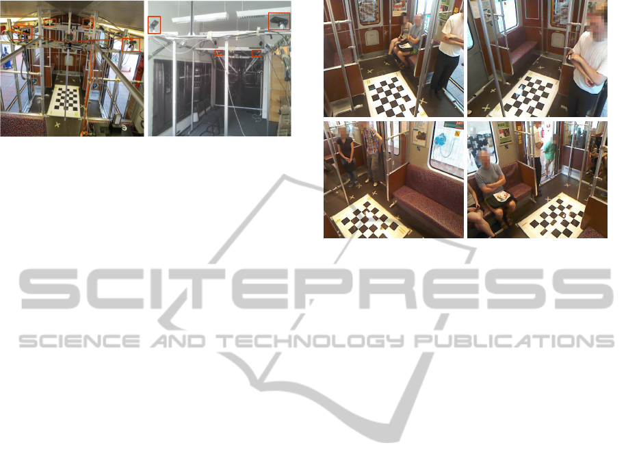
(a) (b)
Figure 3: (a) Camera mounting configuration within the
train wagon and (b) in the simulated environment.
an acquisition rate of ≈ 19fps. Every sensor is con-
nected to a dedicated USB bus due to the high rate of
information generated from both infrared and RGB
camera.
One of the main drawbacks of using multiple
structured light sensors is the drastic reduction of the
depth image quality due to the intersection of near-
infrared light in space. Therefore, all sensors were
oriented towards the lower center of the scene restrict-
ing the overlapping only in the lower part of the FOV.
Concerning hardware performance, computers are
configured with an Intel Core i7-3770 processor,
16GB RAM and a Samsung 840 Pro SSD. In present
state, the complete framework is only able to run of-
fline while real time processing would require better
hardware performance but also further software opti-
mization. Data from all sensors are processed with a
frame rate of ≈ 2 fps.
4.2 Calibration and Bundle Block
Adjustment
There are several libraries (eg. OpenNI, Freenect)
which provide out-of-the-box calibration parameters
of the Kinect sensor. Nevertheless, for achieving
maximum possible accuracy of the generated point
clouds, a more precise calibration is required. Main
advantage of the Kinect sensor is that it uses low dis-
tortion lenses with faintly apparent displacement er-
rors around the corners/edges of the images. The
calibration was performed using a regular chessboard
with pattern size 2cm and inner dimensions of 5 ×7
rows and columns respectively. Since infrared and
RGB sensors cannot work simultaneously, they were
triggered to switch on and off continuously (a switch
lasts 0.5 seconds), in order to acquire roughly the
same chessboard data from the different perspectives.
Detection and acquisition of chessboard points was
done in a live mode using OpenCV’s chessboard cor-
ner detector, which also delivers subpixel accuracy.
Figure 4: Regular chessboard used as a reference system for
all sensors mounted in the train wagon.
The lenses were modeled using Brown’s 10 paramet-
ric model (Brown, 1971). To avoid any disturbances
of the speckles coming from the infrared emitter in
the infrared camera, the emitter was covered with tape
and an external hydrogen lamp was used for detecting
the chessboard corners. A total amount of 100 im-
ages was acquired and split (using a random selection
algorithm) in 10 different sets of 24 images each on
which the calibration was performed independently.
Due to the multi-camera configuration in the
wagon, every sensor produces different results which
in turn can contribute for improving the quality of
the extracted foreground (e.g. registration of all fore-
grounds, solving occlusion problems, etc.). Although
current working status involves processing all sensors
in parallel applying algorithm 1 to every sensor, re-
sults are automatically transformed into a common
coordinate system for better comparing the data be-
tween them but also, in long term, fuse all informa-
tion in a multi-sensor approach. The Efficient Per-
spective n Point algorithm (Lepetit et al., 2009) was
used for transforming all sensors into a global coor-
dinate system defined by a large chessboard with pat-
tern size of 15cm (see Fig. 4). The accuracy of the
camera external parameters (reprojection error) was
in the range of less than a quarter of a pixel. Finally,
we improved the accuracy of the camera’s poses by
setting the results from the previous step as approx-
imate initial values to a photogrammetric bundle ad-
justment. Internal parameters of the sensors remained
fix (due to accurate lens correction parameters) and
only the external orientation parameters were refined
delivering a variance of the unit weight, σ
o
= 0.16 pix-
els. Ground control points were generated setting the
Z value to zero (coplanar reference object) and X-Y
values according to the number of rows, columns and
Towardsa3DPipelineforMonitoringandTrackingPeopleinanIndoorScenariousingMultipleRGBDSensors
197
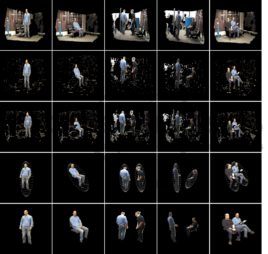
Figure 5: From top row to bottom: raw point clouds from different scenarios; foreground masks extracted by (Kammerl et al.,
2012) approach; results from cloud to cloud background subtraction using a global threshold; The foregrounds extracted by
our approach together with their encapsulated ellipsoids; ground truth masks generated by the implementation of (Shotton
et al., 2013) in the OpenNI framework.
pattern size respectively. The main reason for using
this form of reference system is the fact that it can be
easily used as a reference object for all cameras. On
the other hand, coplanar objects lack of spatial distri-
bution information and introduce several geometrical
constrains.
4.3 Object Extraction and Tracking
Different scenarios, similar to the ones in the train
wagon, were captured in a simulated train field for
testing and evaluating the quality performance of al-
gorithm 1. Our approach was checked against (Kam-
merl et al., 2012) and a common cloud to cloud back-
ground subtraction using a global distance thresh-
old, setting the borderline between foreground and
background. To the best of our knowledge, there
are no other background subtraction approaches that
could be compared against ours as most of them are
heavily dependent on machine learning algorithms.
Ground truth was generated by detecting the human
figure from the depth images using the skeleton track-
ing algorithm implemented in the OpenNI framework
(Shotton et al., 2013). The extracted figure was then
VISAPP2015-InternationalConferenceonComputerVisionTheoryandApplications
198
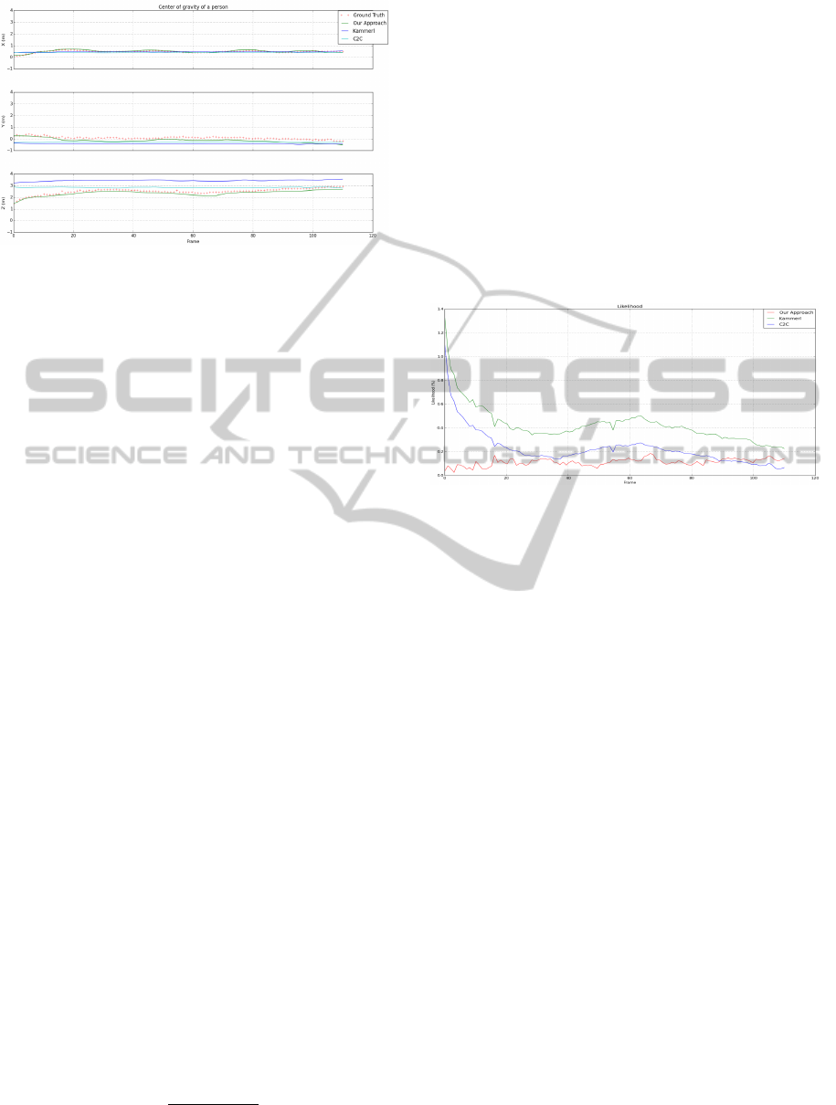
Figure 6: 3D trajectory of the center of gravity of a person
as computed by the ellipsoid, projected in X,Y and Z planes.
projected into 3D space using the internal calibra-
tion information of the corresponding sensor. Results
from different camera views and scenarios are given
in figure 5.
It is clear that our method outperforms the two
other approaches, producing better quality foreground
masks in all cases. All parameters were empirically
defined after extensive evaluation and testing: for the
octree, it was important to provide a leaf size that con-
trols the amount of voxels in the cloud and was set to
0.10m. The depth trimming of the point cloud was
performed using a pass-through filter preserving all
points up to 4m. Also, contours on the binary image
that had less than a 1000 or more then 7000 pixels re-
spectively were removed. Finally, the global distance
threshold for the cloud to cloud subtraction was set to
5cm.
Last step involves fitting an ellipsoid around the
human figure and extracting its geometrical charac-
teristics over time. Kalman filter was applied to all
attributes of the ellipsoid for removing any unwanted
sparks and smoothing out the data. Figure 6 shows
150 frames from a trajectory of a person as computed
by the aforementioned approaches together with the
ground truth generated from (Shotton et al., 2013).
It is clear that our method produces greater stabil-
ity compare to the other two methods as they tend to
follow a constant plateau effect. This is because the
amount of noise in the scene does not allow the ellip-
soid to be encapsulated only around the body but also
incorporating the noise around it. On the contrary, our
approach follows the ground truth trajectory in a more
likewise manner.
The trajectory of every approach was checked
against the ground truth using the following likeli-
hood formulation:
L
t
=
kP
t
−P
t
GT
k
2
kP
t
GT
k
2
(15)
where L
t
is the likelihood (in %) of every point on a
trajectory at time t against its equivalent ground truth
point at time t, k·k
2
represents the Euclidean (second)
norm and P
t
, P
t
GT
are points on the trajectory of any
of the two approaches and ground truth respectively.
Figure 7 clearly shows the quality of likeliness be-
tween different approaches with respect to the ground
truth. Our pipeline provides closer fitting percentage
to the ground truth, where the rest tend to be far away
from it, as a result of severe noise in the environment.
This is observed in the areas higher than ≈15% which
means that the distance of a point in the trajectory is
approximately a quarter away compare to the distance
of the ground point from its natural zero origin.
Figure 7: Likelihood of the distance error for every point in
the trajectory with respect to its ground truth.
One of the main drawbacks of our approach is the
instant increase of the size of the ellipsoid when two
or more people come very close to each other. Al-
though this is controlled given a minimum and maxi-
mum size of a contour, it still remains an unsolved is-
sue and it’s currently investigated. All parameters of
the ellipsoid are saved in an XML file and imported
in a tracking visualizer for monitoring the behavior of
people in the train. Unfortunately, this visualizer was
developed by another partner within the project and
therefore due to NDA we are not yet allowed to make
any results publicly available. Finally, psychologists
in the social and cultural anthropology field where re-
sponsible for interpreting and classifying the behav-
iors as normal or abnormal.
5 CONCLUSIONS AND FUTURE
WORK
This paper introduced a method of extracting, moni-
toring and tracking people in an indoor train environ-
ment using a network of sensors, were current state of
the art machine learning detection approaches would
fail due to the challenging environmental perturba-
tions. Current state of the work involves processing
all cameras in parallel using algorithm 1. Results
Towardsa3DPipelineforMonitoringandTrackingPeopleinanIndoorScenariousingMultipleRGBDSensors
199

show that the proposed method can deliver high qual-
ity foreground segmentation masks compare to the
ones of (Kammerl et al., 2012) and cloud to cloud
subtraction. We were able to eliminate the noise and
preserve only the moving person in the scene by im-
proving the approach of (Kammerl et al., 2012) in
algorithm 1. Results in the previous section also
showed that the accuracy of the foreground strongly
reflects on the accuracy of the ellipsoid. Noise in
the surrounding can provide misleading information
which does not help the monitoring process and even-
tually will result false interpretation of the behavior.
We were able to achieve a deviation less than 15%
from the ground truth in comparison to the other ap-
proaches, most of the time retaining a deviation larger
than 40% from ground truth. We also tried to filter
out these noisy blobs from the processed clouds using
different 3D filters but in all cases the resulting fore-
ground was very much affected by the noise in the
scene.
In the preprocessing steps, calibration was manda-
tory for maximizing reliability of the produced re-
sults. The internal parameters were mainly used for
generating the point clouds and also for projecting the
3D points on a binary image as discussed in section
2.3. Bundle adjustment was performed keeping the
internal parameters fixed in the convergence process
optimizing only the external values of the cameras.
Future research involves enhancing the quality of
the existing foreground so it remains invariant to noise
in the point cloud. This is an essential step because
the accuracy of the ellipsoid is highly dependent from
the accuracy of the foreground. Taking advantage of
the multi camera configuration, all data extracted by
each sensor could be fused in order to increase the
confidence and the quality of the foreground. More-
over, a multi camera approach could also handle mul-
tiple human instances in the scene and tackle the prob-
lem of occlusions. In terms of computational perfor-
mance, this would require having one computer per
sensor due to the amount of power required to man-
age all sensors simultaneously.
We have acquired many data sets from the train
experiment, containing several scenarios of everyday
situations in a wagon. This dataset will become pub-
licly available in the future, containing several RGBD
data from different scenarios, calibration parameters
for every sensor and benchmark information.
REFERENCES
Baum, M. and Hanebeck, U. D. (2013). Extended object
tracking with random hypersurface models. CoRR,
abs/1304.5084.
Brown, D. C. (1971). Close-range camera calibration. Pho-
togrammetric Engineering, 37(8):855–866.
Buys, K., Cagniart, C., Baksheev, A., De Laet, T., De Schut-
ter, J., and Pantofaru, C. (2014). An adaptable system
for rgb-d based human body detection and pose esti-
mation. J. Vis. Comun. Image Represent., 25(1):39–
52.
Faion, F., Baum, M., and Hanebeck, U. D. (2012). Tracking
3D Shapes in Noisy Point Clouds with Random Hy-
persurface Models. In Proceedings of the 15th Inter-
national Conference on Information Fusion (Fusion
2012), Singapore.
Hegger, F., Hochgeschwender, N., Kraetzschmar, G., and
Ploeger, P. (2013). People Detection in 3d Point
Clouds Using Local Surface Normals, volume 7500 of
Lecture Notes in Computer Science, book section 15,
pages 154–165. Springer Berlin Heidelberg.
Kammerl, J., Blodow, N., Rusu, R. B., Gedikli, S., Beetz,
M., and Steinbach, E. (2012). Real-time compression
of point cloud streams. In IEEE International Confer-
ence on Robotics and Automation (ICRA), Minnesota,
USA.
Lepetit, V., F.Moreno-Noguer, and P.Fua (2009). Epnp: An
accurate o(n) solution to the pnp problem. Interna-
tional Journal Computer Vision, 81(2).
Moshtagh, N. (2005). Minimum volume enclosing ellip-
soid.
Munaro, M., Basso, F., and Menegatti, E. (2012). Tracking
people within groups with rgb-d data. In IROS, pages
2101–2107. IEEE.
Shotton, J., Girshick, R., Fitzgibbon, A., Sharp, T., Cook,
M., Finocchio, M., Moore, R., Kohli, P., Criminisi,
A., Kipman, A., and Blake, A. (2013). Efficient hu-
man pose estimation from single depth images. IEEE
Transactions on Pattern Analysis and Machine Intel-
ligence, 35(12):2821–2840.
Sigalas, M., Pateraki, M., Oikonomidis, I., and Trahanias,
P. (2013). Robust model-based 3d torso pose estima-
tion in rgb-d sequences. In The IEEE International
Conference on Computer Vision (ICCV) Workshops.
Todd, M. J. and Yildirim, E. A. (2007). On khachiyan’s
algorithm for the computation of minimum-
volume enclosing ellipsoids. Discrete Appl. Math.,
155(13):1731–1744.
Ziegler, J., Nickel, K., and Stiefelhagen, R. (2006). Track-
ing of the articulated upper body on multi-view stereo
image sequences. In CVPR (1), pages 774–781. IEEE
Computer Society.
VISAPP2015-InternationalConferenceonComputerVisionTheoryandApplications
200
