
TE Modes in Liquid Crystal Optical Fibers Embedded with
Conducting Tape Helix Structure
Masih Ghasemi and P. K. Choudhury
Institute of Microengineering and Nanoelectronics, Universiti Kebangsaan Malaysia, U.K.M. Bangi, 43600, Malaysia
Keywords: Liquid Crystal Fibers, Complex Optical Microstructures, Electromagnetic Waves.
Abstract: The transverse electric (TE) behaviour of light in a doubly-clad cylindrical optical fiber loaded with radially
anisotropic liquid crystal material at the outermost cladding is investigated. Moreover, this situation is
studied when a conducting tape helix structure is introduced at the boundary of the isotropic dielectric core
and the inner dielectric clad of the fiber. The outer clad is considered to be made of anisotropic nematic
liquid crystal (NLC). Using Maxwell’s electromagnetic field equations, confinement plots are obtained for
the transmitted power in each scenario, under the situation of varying core dimension, and compared.
Results confirm the achievement of better confinement in the liquid crystal layer of the conducting tape
helix loaded fiber, which can even be tailored by using different angle of helix pitch.
1 INTRODUCTION
Nonlinear properties of liquid crystals (LCs) have
been utilized in variety of applications in optics
industries. For instance, the latest research illustrates
the impact of temperature on the optical harmonic
generation in fiber-coupled nematic LCs (Trashkeev
et al., 2014). Other report shows that LC fiber array
would confine transmission of high energy laser
pulses, which can be exploited as protector for
downstream sensors (Khoo et al., 1996). The
literature on LC based waveguides proved potentials
of research concealed behind the dispersion property
of radial anisotropy orientation of LC material
(Ioannidis et al., 1991).
Apart from the aforementioned applications, LCs
are greatly useful for devising various forms of
sensing and field coupling needs that include optical
sensors as well. For example, such materials become
indispensable in fabricating lasers (Dolgaleva et al.,
2009), polarimetric sensors (Wolinski et al., 2001),
dispersion compensators (Akbulut, 2006), imaging
systems (Gebhart et al., 2005), electric field and
temperature sensors (Wolinski et al., 2006),
photonic crystal based guides (Wolinski et al.,
2005), optical filters (Stratis et al., 2001), integrated
optic devices (d’Alessandro, 2004) etc. Within the
context, optical fibers based on liquid crystals can be
given a serious thought, and the sensing applications
of such LC fibers have been investigated before
(Choudhury, 2014). It has been reported earlier that
tapering the fiber cross-section greatly enhances the
optical sensing capability of LC based fibers
(Choudhury et al., 2011).
Amalgamation of material and geometrical
properties could be the possible way to govern the
lightwave propagation in waveguide technologies
(Choudhury et al., 2004; Ghasemi et al., 2014).
Apart from the LC material, perfectly conducting
twisted clad fibers have also been reported as useful
complex mediums wherein the pitch angle of
conducting sheath or tape helices impose great
control over the propagation characteristics of
electromagnetic waves (Ghasemi et al., 2014).
In the present paper, we deal with a three-layer
optical fiber with the outermost region being coated
with radially anisotropic LC material, and the inner
dielectric core-clad interface is loaded with
conducting tape helix structure. It must be
remembered that the thickness of conducting tape
remains infinitesimally small, which makes one to
assume this parameter as almost vanishing. As such,
the perpendicular component of surface current over
the tape may be ignored, as compared to the parallel
one. With the assumption of the availability of the
flow of current over the surface of tape, recent report
emphasized that the LC layer is more prone to
confine the transmission of power for the lowest
zero-order hybrid mode (Ghasemi et al., 2014). In
Ghasemi M. and Choudhury P..
TE Modes in Liquid Crystal Optical Fibers Embedded with Conducting Tape Helix Structure.
DOI: 10.5220/0005319800610066
In Proceedings of the 3rd International Conference on Photonics, Optics and Laser Technology (PHOTOPTICS-2015), pages 61-66
ISBN: 978-989-758-092-5
Copyright
c
2015 SCITEPRESS (Science and Technology Publications, Lda.)

the present work, we emphasize on the confinement
due to transverse electric (TE) modes under varying
tape helix pitch angle. Results reveal that small
changes in the angle of pitch bring in considerable
shifts in the characteristics of power transmission
properties. The TE
01
mode with lower propagation
constants transmits lower amount of power, and the
fractional power increases with the increase in
propagation constant in LC layer of fiber structure
under consideration. The results are also compared
with the situation when the tape helix structure is
eliminated, in order to investigate the effect of the
presence of conducting tape helical windings.
2 THEORY
Figures 1a and 1b, respectively, illustrate the
schematics of LC optical fibers with and without
conducting tape helix loadings. In the case of fig. 1a,
represents the helix pitch angle, which may
assume values between 0 and 90. For the sake of
simplicity, the LC layer is considered to be infinitely
extended in the radial direction, whereas the inner
isotropic dielectric core and the clad sections have
the radius values as and , respectively. The
refractive index (RI) of the core and the inner clad
regions are taken to be
and
, respectively.
Owing to the ordinary and the extraordinary
orientations of the outermost LC layer, we consider
and
as the respective RI values belonging to
each orientation. Numerically, the RI distribution
profile may be written as
.
Figure 1: Schematic diagram of the LC fiber embedded
with conducting tape helix (a) and without tape helix (b)
structure.
The cylindrical polar coordinate system ,, is
used for the analysis of fibers with conducting tape
helix loadings. We consider that the time - and axis
-harmonic electromagnetic waves propagate along
the -direction. Considering fig. 1a, the parameters
, and , respectively, represent the pitch angle of
conducting tape helix, width of the conducting tape
and the distance between two successive tape helical
windings. However, it must be noted that and
are related through
arctan/2
(1)
Equation (1) indicates that the helix pitch angle
essentially depends on the fiber core dimension. As
such, in the present investigation, computations are
made for different values of core diameter, which
provide particular values of pitch angle.
It must be remembered that, while investigating
the TE
01
mode in the fiber structure, the only
available fundamental electric fields component is
, which is independent of the coordinate ; the
other components of field vanish. As such, we
consider
/0, and the solutions of the
coupled differential equations contain Bessel and the
modified Bessel functions (Snyder et al., 1983).
,
1,0:
0
2:
0,
1,
3:
∞
(2)
Equation (2) is written in symbolic form where the
number of layer that corresponds to each region of
fiber and represents subpart of the combined
Bessel function within each layer. More explicitly,
,
is Bessel function of the first kind in the first
layer,
,
and
,
are the modified Bessel
functions in the second layer, and
,
is Hankel
function of the second kind in the third layer of the
LC fiber. Furthermore, the quantities , and
related to the core, the inner clad and the outer clad
parameters, respectively, are defined as
√
(3)
√
(4)
√
(5)
Upon substituting the above eq. (2) in Maxwell’s
equations, we finally obtain the following axial,
radial and azimuthal components of electromagnetic
field in the different fiber sections:
,
,
(6)
2
2
(a)
2
2
(b)

,
,
2
,
,
,
,
(7)
,
(8)
,
,
,
,
(9)
,
,
2
,
,
,
,
,
,
2
,
,
,
,
(10)
,
,
(11)
,
,
(12)
,
,
2
,
,
,
,
(13)
,
(14)
In the above equations, , , and are the
(unknown) arbitrary constants, which are to be
determined by the use of suitable boundary
conditions (Ghasemi et al., 2014). The relevant
analytical treatment ultimately yields the values of
these constants as
ϱ
(15)
ϱ
(16)
Cϱ
(17)
Dϱ
(18)
where ϱ
is the total current density over surface of
tape helix, as obtained by using the tangential
components of magnetic field in the core and the
inner clad regions of fiber. Corresponding to the
situation of TE
01
mode, ϱ
would assume the form
ϱ
(19)
Further, the other symbols used in eqs. (15)(18)
have meanings as follows:
(20)
(21)
(22)
(23)
(24)
(25)
with
,
(26)
,
,
(27)
,
(28)
,
(29)
,
,
(30)
,
,
(31)
,
(32)
,
(33)
,
,
(34)
,
,
(35)
,
(36)
,
,
(37)
In the case of fiber with the loading of
conducting tape helix (fig. 1a), we consider that the
flow of current takes place over the surface of tape.
However, in the case of fig. 1b, fields remain
continuous at each boundary, and power
confinements are derived from the continuity
conditions. The elimination of conducting tape will
essentially cause the expressions of electric and
magnetic components to have different set unknown
constants, viz.
,
,
and
. Thus, we can have
the field components in this case as
,
,
(38)
,
,
2
,
,
,
,
(39)
,
(40)

,
,
,
,
(41)
,
,
2
,
,
,
,
,
,
2
,
,
,
,
(42)
,
,
(43)
,
,
(44)
,
,
2
,
,
,
,
(45)
,
(46)
Equations (38)(46) can be exploited to
implement the continuity conditions of fields
corresponding to the non-helix kind of LC fiber.
Further, eqs. (26)(37) can be utilized in order to
extract the expressions for the unknown constants
corresponding to the TE
01
mode excitation. Finally,
the unknown constants
and
will assume the
forms, in terms of
, as follows:
(47)
(48)
(49)
with
(50)
(51)
Finally, in order to compute the propagation of
power through the LC fiber structures of fig. 1, we
use eqs. (15)(18) corresponding to the case of
conducting tape helix based fiber (fig. 1a), whereas
eqs. (47)(49) for the fiber without the existence of
tape helix structure (fig. 1b). Furthermore, by the use
of electromagnetic field equations corresponding to
the case of particular fiber, the expressions for the
confinement of power in the different fiber regions
for the respective LC fiber structure can be deduced.
3 RESULTS AND DISCUSSION
We now make attempts to evaluate the confinement
of power in the fiber structures of fig. 1 due to the
transmission of the TE
01
mode. At this point, this
must be remembered that, as stated above, the entire
mathematical treatment is not incorporated into the
text, in order to avoid the length of the manuscript.
For the computational purpose, we assume the RI
values of the core and the inner clad sections as
1.462 and
1.458, respectively, while in
the LC layer we take the nematic liquid crystal as
BDH mixture 14616 having the respective ordinary
and the extra ordinary RI values as
1.457 and
1.5037. The wavelength of operation is taken
as 633 nm. Further, it must be remembered that, in
the evaluation of power, the distance between two
consecutive tape helix windings is governed by the
following expression:
/2
/
(52)
Figures 2a, 2b and 2c illustrate the plots of the
propagation of power in the core, the inner clad and
the outer clad sections, respectively, under the
situation when the LC fiber is assumed to have a
loading of conducting tape helix with specific
orientation. For this purpose, we consider five
different values of fiber core dimension through
setting the value of as 5 µm, 15 µm, 30 µm, 50 µm
and 70 µm. Also, the inner clad size is taken to be
fixed with as 150 µm, while the outermost LC clad
is extended to infinity. Furthermore, we consider
that , the width of the tape, is 10 times smaller than
the pitch formed due to the gap between two
successive windings of conducting tape helix. Since
the pitch of helix has inverse relationship with the
core size, the lowest value of pitch corresponds to
the largest core size. The aforementioned values of
give the respective values of helix pitch angles as
0.79, 0.26, 0.13, 0.08 and 0.06. In figs. 2, plots
of confinements are illustrated corresponding to
these specific values of that essentially represent
varying orientation of conducting tape helix.
We observe from fig. 2a that the confinement
due to the TE
01
mode remains very small in the core
section, particularly for the higher values of
propagation constant. Corresponding to all the
values of fiber core dimension, it gradually
decreases with the increase in -values. In the inner
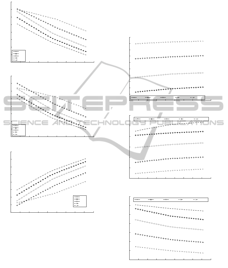
Figure 2: TE
01
mode power confinement patterns in the
fiber (a) core, (b) inner clad, and (c) LC outer clad in the
case of conducting tape helix loaded LC fiber.
clad section too, the behaviour of power distribution
remains almost similar (fig. 2b). Figure 2c illustrates
that, for higher -values, the confinement is
markedly increased, and remains the maximum
corresponding to the maximum value of helix pitch
angle. For 0.79°, we find from fig. 2c that the
confinement varies between 20%65% over the
allowed values of propagation constant.
In order to have a comparative look,
investigations are made of the LC fiber without the
loading of the conducting tape helix windings, and
the corresponding plots are shown in fig. 3. In this
set of figures, we observe that, in every section of
fiber structure, confinement due to the TE
01
mode
becomes smaller, as compared to the situation of
fiber with tape helix (fig. 2).
Figure 3: TE
01
mode power confinement patterns in the
fiber (a) core, (b) inner clad, and (c) LC outer clad in the
case of LC fiber.
Our prime interest remains on the way to
increase the confinement of power in the outermost
section of fiber. We, therefore, observe that the fiber
1.447 1.4475 1.448 1.4485 1.449 1.4495 1.45 1.4505 1.451 1.4515
x 10
7
0.2
0.25
0.3
0.35
0.4
0.45
0.5
0.55
(m
-1
)
Pco
P = 0.43356
m
b = 150
m
= 0.1 P
=0.7 9
=0.2 6
=0.1 3
=0.0 8
=0.0 6
1.447 1.4475 1.448 1.4485 1.449 1.4495 1.45 1.4505 1.451 1.4515
x 10
7
0.2
0.25
0.3
0.35
0.4
0.45
0.5
0.55
(m
-1
)
Pic
P = 0.43356
m
b = 150
m
= 0.1 P
=0.7 9
=0.2 6
=0.1 3
=0.0 8
=0.0 6
1.447 1.4475 1.448 1.4485 1.449 1.4495 1.45 1.4505 1.451 1.4515
x 10
7
-0.1
0
0.1
0.2
0.3
0.4
0.5
0.6
0.7
(m
-1
)
Poc
P = 0.43356
m
b = 150
m
= 0.1 P
=0.7 9
=0.2 6
=0.1 3
=0.0 8
=0.0 6
1.447 1.4475 1.448 1.4485 1.449 1.4495 1.45 1.4505 1.4 51 1.4515
x 10
7
0
0.02
0.04
0.06
0.08
0.1
0.12
0.14
0.16
0.18
0.2
(m
-1
)
Pco
a=5
m a=15
m a=30
m a=50
m a=70
m
1.447 1.4475 1.448 1.4485 1.449 1.4 495 1.45 1.4505 1.451 1.4515
x 10
7
0.38
0.4
0.42
0.44
0.46
0.48
0.5
(m
-1
)
Pic
a=5
m a=15
m a=30
m a=50
m a=70
m
1.447 1.4475 1.448 1.4485 1.449 1.4495 1.45 1.4505 1.4 51 1.4515
x 10
7
0.4
0.42
0.44
0.46
0.48
0.5
0.52
0.54
(m
-1
)
Poc
a=5
m a=15
m a=30
m a=50
m a=70
m
(a)
(b)
(c)
(a)
(b)
(c)

embedded with conducting tape helix structure
remains capable to sustain more amount of power in
the outermost liquid crystal section. This essentially
makes the structure possibly more efficient for its
usages like the integrated optic devices for field
coupling and/or in the area of optical sensing.
4 CONCLUSIONS
From the foregoing analyses, it can be inferred that
the LC fiber structure loaded with conducting tape
helix windings would be more useful for
applications in optics industry. This is primarily due
to the reason that the outermost liquid crystal region
becomes more prone to confine higher amount of
power to be used particularly for the evanescent
field based optical applications (e.g. sensing or
coupling of electromagnetic fields). These
conclusive remarks are drawn based on comparing
the results obtained for ordinary LC clad fibers with
radially anisotropic liquid crystal materials.
ACKNOWLEDGEMENTS
The authors are thankful to the Ministry of Higher
Education (Malaysia) for granting the financial
support to the work Also, they are thankful to
Professors B.Y. Majlis and S. Shaari for constant
encouragement and help.
REFERENCES
Trashkeev, S. I., Nyushkov, B. N., 2014. Thermal
enhancement of optical harmonic generation in a fiber-
coupled nematic liquid crystal. Laser Optics 2014 –
IEEE International Conference, pp. 11.
Khoo, I. C., Wood, M., Guenther, B. D., 1996. Nonlinear
liquid crystal optical fiber array for all-optical
switching/limiting. In LEOS 96 – IEEE Lasers and
Electro-Optics Society Annual Meeting, vol. 2, pp.
211212.
Ioannidis, Z. K., Giles, I. P., Bowry, C., 1991. All-fiber
optic intensity modulators using liquid crystals, Appl.
Opt., vol. 30, pp. 328333.
Dolgaleva, K., Wei, S. K. H., Lukishova, S. G., Chen,
S.H., Schwertz, K., Boyd, R.W., 2009. Enhanced laser
performance of cholesteric liquid crystals doped with
oligofluorene dye. J. Opt. Soc. Am. B, vol. 25, pp.
1496–1504.
Wolinski, T. R., Szymanska, A., 2001. Polarimetric
optical fibres with elliptical liquid-crystal core. Meas.
Sci. Technol., vol. 12, pp. 948−951.
Akbulut, M., 2006. Broadband all-order polarization mode
dispersion compensation using liquid-crystal
modulator arrays. J. Lightwave Technol., vol. 24, pp.
251−261.
Gebhart, S. C., Stokes, D. L., Vo-Dinh, T., Mahadevan-
Jansen, A., 2005. Instrumentation considerations in
spectral imaging for tissue demarcation: comparing
three methods of spectral resolution. Proc. SPIE, vol.
5694, pp. 41−52.
Wolinski, T. R., Szaniawska, K., Ertman, S., Lesiak, P.,
Domanski, A.W., Dabrowski, R., Nowinowski-
Kruszelnicki, E., Wojcik, J., 2006. Influence of
temperature and electrical fields on propagation
properties of photonic liquid-crystal fibres. Meas. Sci.
Technol., vol. 17, pp. 985–991.
Wolinski, T. R., Szaniawska, K., Bondarczuk, K., Lesiak,
P., Domanski, A. W., Dabrowski, R., Nowinowski-
Kruszelnicki, E., Wojcik, J., 2005. Propagation
properties of photonic crystal fibers filled with
nematic liquid crystals. Opto-Electron. Rev., vol. 13,
pp. 59–64.
Stratis, D. N., Eland, K. L., Carter, J. C., Tomlinson, S. J.,
Angel, S.M., 2001. Comparison of acousto-optic and
liquid crystal tunable filters for laser-induced
breakdown spectroscopy. Appl. Spectroscop., vol. 55,
pp. 999−1004.
d’Alessandro, A., Asquini, R., Gizzi, C., Bellini, B.,
Beccherelli, R., 2004. Integrated optic devices using
liquid crystals: design and fabrication issues. Proc.
SPIE, vol. 5518, pp. 123−135.
Choudhury, P. K., 2013. Liquid crystal optical fibers for
sensing applications. Proc. SPIE, vol. 8818, pp.
88180E-1–88180E-10.
Choudhury, P. K., Soon, W. K., 2011. On the transmission
by liquid crystal tapered optical fibers. Optik, vol. 122,
pp. 10611068 (2011).
Choudhury, P. K., Yoshino, T., 2004. TE and TM modes
power transmission through liquid crystal optical
fibers. Optik, vol. 115, pp. 4956.
Ghasemi, M., Choudhury, P. K., 2014. Propagation
through complex structured liquid crystal optical
fibers. J. Nanophoton., vol. 8, pp. 083997-1083997-
13.
Ghasemi, M., Choudhury, P. K., 2014. Waves in tape
helix loaded liquid crystal optical fiber. Proc. SPIE,
vol. 9172, pp. 91720G-1–91720G-8.
Snyder, A. W., Rühl, F., 1983. Single-mode, single-
polarization fibers made of birefringent material. J.
Opt. Soc. Am., vol. 73, pp. 11651174.
