
Micro Sensors for Real-time Monitoring of Mold Spores and Pollen
Kei Tsuruzoe and Kazuhiro Hara
Department of Electrical and Electronics Engineering, School of Engineering, Tokyo Denki University
5 Senjyu-Asahicho, Adachiku, Tokyo 120-8551, Japan
Keywords: Mold Spore, Pollen, Real–time Monitoring, Micro Sensor, Semiconductor Thin Film, Metal Oxide.
Abstract: Organic airborne particles such as mold spores and pollen cause a variety of diseases. Two types of micro
sensors for real-time monitoring of such organic airborne particles have been developed using
semiconductor thin-film. A basic type thin-film sensor has a simple configuration with a double-layered
sensing film deposited on an alumina substrate. A MEMS type sensor is composed of two parts: a sensing
element and a micro heater. Both parts are fabricated by using thin film technology, IC fabrication process
and micromachining technique. The double-layered sensing film is deposited on a diaphragm formed on a
Si substrate. A thin film heater is placed in parallel at a distance of about 50 μm. The resistance of both
sensors steeply decreases and then recovers to the initial value when a mold spore or a grain of pollen
adheres to the surface of the sensing film and burns on it. The resistance change and the recovery time
depend on the size of the organic airborne particles. Thus it is possible to identify the species of the particle
by the developed sensors. The sensors offer simple and inexpensive method to monitor organic airborne
materials.
1 INTRODUCTION
Many people fall in pneumonia by inhalation of
mold spores such as aspergillus fumigatus. At the
same time, the number of people who are allergic to
organic airborne particles such as pollen and house
dust has been increasing. Although human noses are
sensitive to some toxic gases and odors such as burnt
odor and bad smell, human noses cannot detect
organic airborne particles. Therefore, it is required to
develop sensors for these airborne particles.
Some methods have been developed to monitor
airborne
materials so far. Various types of samplers
are usually used to count the number of airborne
mold spores (Hoisington et al., 2014; Whyte et al.,
2007). However, they are disadvantageous in that it
takes several days to culture them on agar. The
gravitational method by a Durham’s sampler is a
common one to obtain the number of pollen
(Konishi et al., 2014). It also takes a lot of time to
get the number because they are observed by the
human eye through an optical microscope. These
two methods are not fit for real-time monitoring of
airborne materials. Particle counters with laser optics
are sometimes used (Weber et al., 2012). However,
they cannot distinguish organic airborne particles
from inorganic particles such as ashes and sands. In
addition, they are complex and expensive in general.
This paper describes novel, inexpensive micro
sensors that are capable of detecting organic
airborne particles such as mold spores and pollen.
Two types of micro sensors have been developed: a
basic type sensor and a MEMS type sensor. The
former has a simple structure with a relatively large
sensing area that is suitable for detection of larger
airborne particles. The latter has a smaller sensing
area that is better suited for detection of smaller
airborne particles.
Both sensors have configurations which are
similar to thin-film gas sensors (Brunet et al., 2012;
Sharma et al., 2011). In addition, similar sensing
materials based on semiconductor metal oxides such
as SnO
2
and Fe
2
O
3
were used for the developed
sensors. In general, these metal oxides are stable at
elevated temperatures and their resistance changes
by the redox reaction on the surface when a reducing
gas or an oxidizing gas is introduced. In ordinary gas
sensors, greater sensing area is better because it
increases the sensitivity to these gases. In this study,
however, the sensing area was reduced to fit for
detection of fine airborne particles.
174
Tsuruzoe K. and Hara K..
Micro Sensors for Real-time Monitoring of Mold Spores and Pollen.
DOI: 10.5220/0005279301740179
In Proceedings of the International Conference on Biomedical Electronics and Devices (BIODEVICES-2015), pages 174-179
ISBN: 978-989-758-071-0
Copyright
c
2015 SCITEPRESS (Science and Technology Publications, Lda.)
2 EXPERIMENTAL
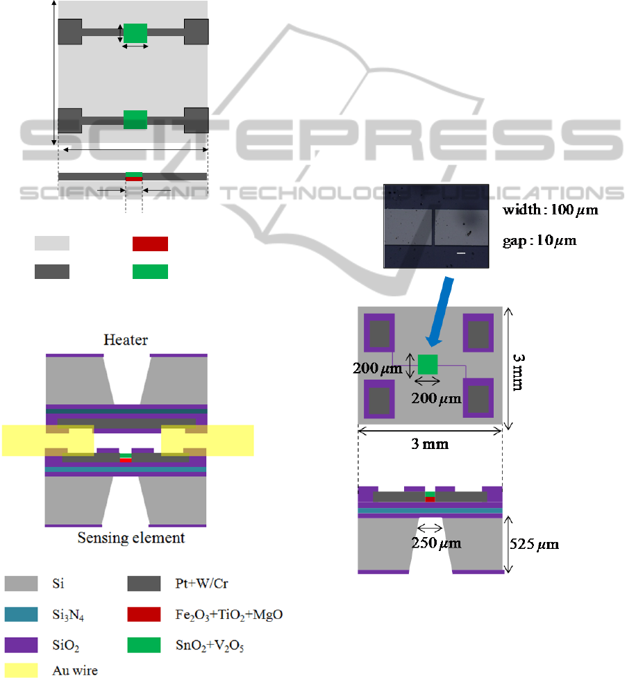
2.1 Sensor Configuration
A schematic top and cross-sectional view of a basic
type micro sensor is shown in Figure 1. A sensing
film was deposited on an Al
2
O
3
substrate. The
sensing film had a double-layered structure. The first
layer was Fe
2
O
3
+TiO
2
(5 mol%) + MgO (4 mol%)
Figure 1: Schematic top and cross-sectional view of a
basic type sensor.
Figure 2: Schematic cross-sectional view of a MEMS type
sensor.
and the second layer was SnO
2
+ V
2
O
5
(4 mol%). Its
sensitivity and stability have been improved by
adopting a double-layered structure (Hiwatari and
Hara, 1998). The thickness of the first and the
second layers was 100nm and 100nm, respectively.
The length and the width of the sensing film
between the electrodes were 15 μm and 100 μm,
respectively. The sensor was heated by a
commercially available Pt heater covered by
alumina ceramics when the sensor response was
tested.
A schematic cross-sectional view of a MEMS
type micro sensor is shown in Figure 2. The sensor
is composed of two parts: a sensing element and a
micro heater. A sensing film was deposited on a
SiO
2
/Si
3
N
4
/SiO
2
diaphragm formed on a Si
substrate. A thin film heater was also made on a
similar diaphragm formed on another Si substrate.
The sensing element and the micro heater were
placed in parallel at a distance of about 50 μm by
inserting gold wires.
Figure 3: Schematic top and cross-sectional view of the
sensing element.
The sensing film was heated by the heater
through the air that existed between the two parts
when the response was examined (Hara, 2013). The
sensing film had a double-layered structure; the
material of the sensing film is the same as that of the
Pt+W
Fe
2
O
3
+TiO
2
+MgO
SnO
2
+V
2
O
5
Al
2
O
3
10 mm
10mm
15 μm
500 μm
300 μm
MicroSensorsforReal-timeMonitoringofMoldSporesandPollen
175
basic type sensor. The thickness of the first and the
second layers was 100 nm and 100 nm, respectively.
The length and the width of the sensing film
between the electrodes were 10 μm and 100 μm,
respectively. The dimension of the Si substrates and
the diaphragms was 3 mm×3 mm×0.5 mm and
250 μm ×250 μm ×7 μm, respectively, for both
elements.
The detailed configuration of the sensing element
and the micro heater is shown in Figure 3 and Figure
4, respectively.
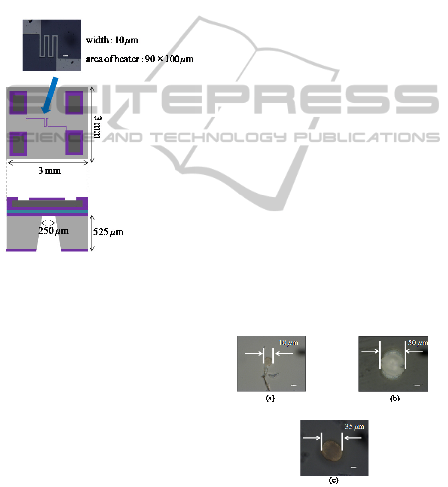
Figure 4: Schematic top and cross-sectional view of the
micro heater.
2.2 Sensor Fabrication
The fabrication process of a basic type micro sensor
is as follows. A Pt+W (5 mol%) film was deposited
on an Al
2
O
3
substrate for use as an electrode and
defined by photolithography. Next, a layer made of
Fe
2
O
3
+TiO
2
(5mol%) + MgO (4 mol%) and another
layer made of SnO
2
+ V
2
O
5
(4 mol%) were
successively deposited to form a sensing film.
Finally, the sensing film was patterned by lift-off
technique. All these thin films were deposited by r.f.
sputtering technique.
The fabrication process of a MEMS type sensor
is described below. A multi-layered SiO
2
/Si
3
N
4
/SiO
2
film was successively deposited on a Si substrate.
The thickness of the SiO
2
, Si
3
N
4
, and SiO
2
films was
4 μm, 2 μm and 1 μm, respectively. Next, a part of
Si was removed by wet etching to make a diaphragm
structure. A triple-layered Cr/Pt + W (5 mol%)/Cr
film was deposited as a sensor electrode and
patterned by photolithography and subsequent
sputter etching. The thickness of Cr, Pt + W and Cr
films was 35 nm, 200 nm and 35 nm, respectively.
Finally, a sensing film was deposited and patterned
by lift-off technique. This process yielded a sensing
element as shown in Figure 3.
A triple-layered thin film heater (Cr/Pt + W (5
mol%)/Cr) was made on a diaphragm formed on
another Si substrate with a similar process. The
heater had a meander pattern, whose total length and
width were 500 μm and 10 μm, respectively. This
process yielded a micro heater as shown in Figure 4.
All these thin films were deposited by r.f. sputtering
technique to fabricate a MEMS type sensor.
The sensing element and the micro heater were
placed in parallel at a distance of about 50 μm by
inserting gold wires between the sensing element
and the micro heater as shown in Figure 2.
2.3 Experimental Setup
The sensor was set in a closed test box made of
acrylic. The inner volume was 5.4 L. The responses
to organic airborne particles such as mold spores and
pollen were examined; the change of the sensor
resistance was measured by using a digital
multimeter.
Both sensing films need to be heated for
operation. The temperature of the basic type sensor
was measured to be 425 Ԩ. The estimated sensor
temperature of the MEMS type sensor ranged from
330 Ԩ to 360 Ԩ , while the estimated heater
operating temperature ranged from 550 Ԩ to 600 Ԩ,
corresponding to the consumed power that ranged
from 125 mW to 140 mW.
2.4 Samples for Detection
Figure 5: Photographs of (a) mold spores, (b) pine pollen,
and (c) cedar pollen.
BIODEVICES2015-InternationalConferenceonBiomedicalElectronicsandDevices
176
Mold spores, pine pollen and cedar pollen were used
as test samples. The photographs of these particles
are shown in Figure 5(a), 5(b) and 5(c), respectively.
The typical diameter was 10 μm, 50 μm and 35 μm,
respectively.
3 SENSING PERFORMANCE
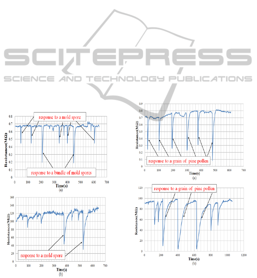
3.1 Response to Mold Spores
The response to mold spores of the basic type sensor
and the MEMS type sensor is shown in Figure 6(a)
and 6(b), respectively. The operating temperature of
the sensing films was about 425 Ԩ and 330 Ԩ ,
respectively. The sensor resistance steeply decreased
after adhesion of mold spores and then gradually
recovered to the initial value as the mold spores
combusted on the sensor surface for both sensors.
For the basic type sensor, the relative resistance
decrease was 34.2 % when a mold spore adhered to
the surface and it was about 70 % when a bundle of
mold spores adhered. The recovery time was 3.2 s
when a mold spore adhered to the surface and it was
about 12 s when a bundle of mold spores adhered.
The repeatability of the response was satisfactory.
Figure 6: Response to mold spores: (a) basic type sensor
and (b) MEMS type sensor.
For the MEMS type sensor, the relative resistance
decrease was 69.3 % when a mold spore adhered to
the surface. The recovery time was 29.5 s. The
response was larger and the recovery time was
slower compared to those for the basic type sensor.
3.2 Response to Pine Pollen
The response to a grain of pine pollen of the basic
type sensor and the MEMS type sensor is shown in
Figure 7(a) and 7(b), respectively. The temperature
of the sensing film was about 425 Ԩ and 330 Ԩ,
respectively. The sensor resistance steeply decreased
after adhesion of a grain of pine pollen and then
gradually recovered to the initial value as a grain of
pine pollen combusted on the sensor surface for both
sensors.
For the basic type sensor, the relative resistance
decrease was 65.9 % when a grain of pine pollen
adhered to the surface. The recovery time was 9.5 s.
For the MEMS type sensor, the relative
resistance decrease was 95.1 %. The recovery time
was 99 s. The response was larger and the recovery
time was slower compared to those for the basic type
sensor.
Figure 7: Response to pine pollen: (a) basic type sensor
and (b) MEMS type sensor.
MicroSensorsforReal-timeMonitoringofMoldSporesandPollen
177
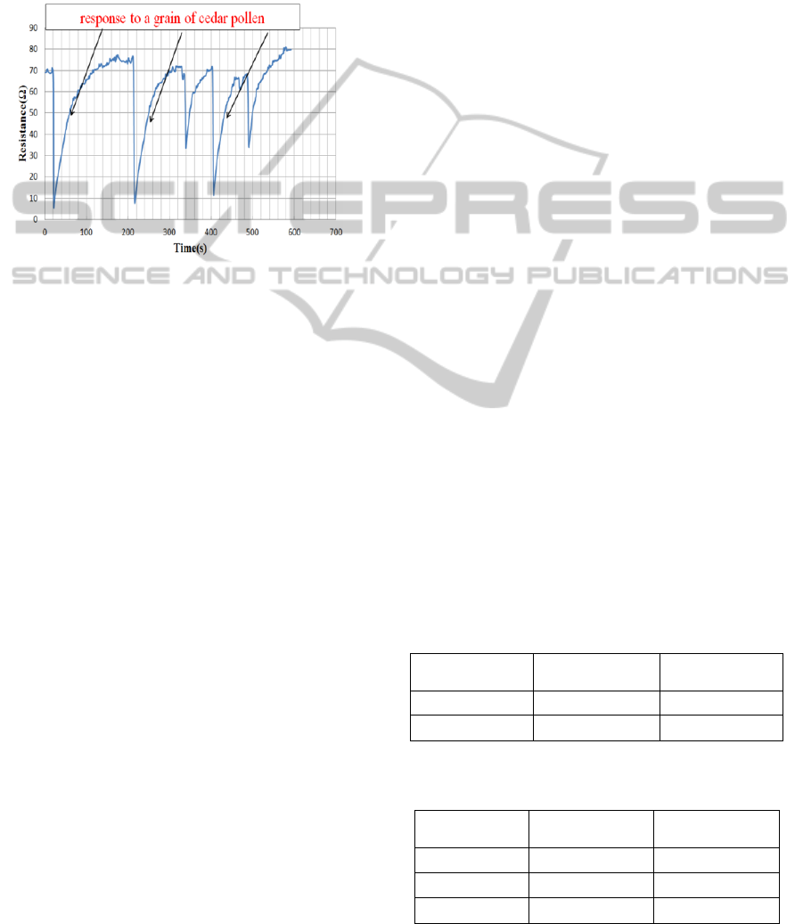
3.3 Response to Cedar Pollen
The response to cedar pollen is shown in Figure 8
for the MEMS type sensor. The temperature of the
sensing film was about 330 Ԩ. The sensor resistance
steeply decreased and then gradually recovered to
the initial value. The relative resistance decrease was
88.9 %. The recovery time was 67 s.
Figure 8: Response to cedar pollen for the MEMS type
sensor.
4 DISCUSSION
4.1 Sensing Principle
The sensing principle for organic airborne particles
is similar to that for reducing gases (Heiland and
Kohl, 1988); hydrogen and carbon atoms in the mold
spores or pollen react with chemisorbed and/or
lattice oxygen on the surface of the metal oxide film,
emitting electrons into the conduction band of the
film. Thus the sensor resistance decreases after
adhesion of organic particles. The resistance value
gradually recovers to the initial one as the particle
burns out on the surface of the sensing film.
The sensor is not selective to a mold spore or a
grain of pollen but sensitive to all organic particles.
However, both the resistance change and the
recovery time are dependent on the size of the
particle.
The observation by the naked eye revealed that
cedar pollen got burned black soon after they
adhered to the sensing surface and then gradually
disappeared. The TDS (Thermal Desorption
Spectroscopy) data on cedar pollen placed on the
surface of the sensing film showed that a peak by
H
2
O appeared at around 150 Ԩ, which was likely to
be derived from the absorbed water in the pollen.
Another peak by H
2
O appeared at around 300 Ԩ,
which was likely to be one of the combusted gases.
Two peaks by CO and CO
2
appeared at around 300
Ԩ and 320 Ԩ, respectively. Both were supposed to
be combusted gases. These results indicate that the
pollen burned on the surface of the sensing film.
Liquid components usually evaporate from the
sensing surface because it is maintained above 330Ԩ.
4.2 Identification of Species
A larger organic particle contains more hydrogen
and carbon atoms and consumes more oxygen atoms
on the surface of the sensing film, emitting more
electrons into the semiconductor film. The resultant
relative resistance decrease is greater for a larger
particle. In addition, it takes a longer time to
combust a larger particle. So the recovery time is
slower for a larger particle.
The relative resistance decreases and the
recovery times are summarized in Table 1 and 2 for
the basic type sensor and the MEMS type sensor,
respectively. The smallest relative resistance change
and the fastest recovery time were observed for a
mold spore with a diameter of 10 μm that was the
smallest particle in the experiment, while the largest
relative resistance change and the slowest recovery
time were observed for a grain of pine pollen with a
diameter of 50 μm that was the largest particle. The
medium relative resistance change and the recovery
time were observed for a grain of cedar pollen with a
diameter of 35 μm. Thus it is possible to estimate the
particle size from the resistance decrease and the
recovery time so as to identify the species of the
particles. For example, a grain of cedar pollen that
may cause allergy can be distinguished from a grain
of pine pollen that may not cause allergy based on
the resistance change and the recovery time.
Table 1: Average decrease of resistance and average
recovery time for the basic type sensor.
Measured
substance
Decrease of
resistance (%)
Recovery time
(s)
Mold spore 34.2 3.2
Pine pollen 65.9 9.5
Table 2: Average decrease of resistance and average
recovery time for the MEMS type sensor.
Measured
substance
Decrease of
resistance (%)
Recovery time
(s)
Mold spore 69.3 29.5
Pine pollen 95.1 99
Cedar pollen 88.9 67
BIODEVICES2015-InternationalConferenceonBiomedicalElectronicsandDevices
178

4.3 Features of Two Types of Micro
Sensors
The basic type sensor has a larger sensing area. So it
is suitable for detection of a larger particle such as
pollen. On the other hand, the MEMS type sensor
has a smaller sensing area. So it is better suited for
detection of a smaller particle such as mold spores.
The experimental results reveal that the MEMS type
sensor exhibits larger relative resistance change to a
mold spore compared to the basic type sensor. Thus
it is essential to minimize the sensing area for
detection of a small particle.
The recovery time of the MEMS type sensor was
much slower than that of the basic type sensor for
both mold spores and pollen. This characteristic
feature results from the lower operating temperature
of the MEMS type sensor. Some other experiments
show that both the resistance decrease and the
recovery time strongly depend on the temperature of
the sensing film. So it is necessary to optimize the
temperature of the sensing film for specific particles
to be detected.
The consumed power of the MEMS type sensor
was reduced to about 125 mW by adopting heat-
insulated structure with use of diaphragm. It is small
enough for a portable or wearable detector of
airborne particles.
5 CONCLUSIONS
Two types of micro sensors for real-time monitoring
of organic airborne particles have been developed
using semiconductor thin-film: a basic type thin-film
sensor a MEMS type sensor. Both sensors
successfully detected a mold spore or a grain of
pollen. Based on the resistance change and the
recovery time, it is possible to identify the species of
the particle by the developed sensors. The
repeatability of the sensor response was satisfactory.
The MEMS type sensor was better suited for
detection of smaller particles. Both sensors offer
simple and inexpensive method to monitor organic
airborne materials. Since the consumed power of the
MEMS type sensor is about 125 mW, it can be used
as a portable or wearable detector.
REFERENCES
Hoisington A. J. et al., 2014. Building and Environment,
80.
Whyte W. et al., 2007. Aerosol Science, 38.
Konishi S. et al., 2014. Science of the Total Environment,
499.
Weber K. et al., 2012. Atmospheric Environment, 48.
Brunet E. et al, 2012. Sensors and Actuators B, 165.
Sharma A. et al., 2011. Sensors and Actuators B, 156.
Hiwatari, T., Hara K., 1998. Trans. IEE of Japan, 118-E.
Hara K., 2013. Biochemical Sensors-Mimicking Gustatory
and Olfactory Senses ed. by Toko K., Pan Stanford
Publishing Pte. Ltd., Singapore.
Heiland G., Kohl D., 1988. Chemical Sensor Technology
ed. by Seiyama T., Elsevier, Amsterdam.
MicroSensorsforReal-timeMonitoringofMoldSporesandPollen
179
