
A Wide-band and User-friendly EEG Recording System for
Wearable Applications
Lorenzo Bisoni, Enzo Mastinu and Massimo Barbaro
Department of Electrical and Electronic Engineering, University of Cagliari, Piazza dArmi, Cagliari 09123, Italy
Keywords:
EEG Recorder, Wearable EEG, Wide-band EEG, Wireless, Bluetooth EEG.
Abstract:
A wireless, wearable and non-invasive EEG recording system is proposed. The system includes a low-power
8-channel acquisition module and a Bluetooth (BT) transceiver to transmit acquired data to a remote platform.
It was designed with the aim of creating a cheap and user-friendly system that can be easily interfaced with
the nowadays widely spread smartphones or tablets by means of a mobile-based application. The presented
system, validated through in-vivo experiments, allows EEG signals recording at different sample rates and
with a maximum bandwidth of 524Hz. It was realized on a 19cm
2
custom PCB with a maximum power
consumption of 270mW.
1 INTRODUCTION
The electroencephalogram (EEG) is a common tech-
nique for detecting symptoms of neurological dis-
eases such as epilepsy, sleep disorders, anxiety and
learning disabilities. These pathologies have a great
impact on people common life and are quite common.
For example anxiety disorders affects approximately
13.6% of the European population (Alonso J., 2004),
and, in 2010, its overall cost in Europe was e74.4 bil-
lion (J. Olesen, 2012). Most of the mentioned mental
disorders require long-term EEG monitoring tofollow
the course of the disease and sometimes to prevent
further degradations of the patient condition such as
epileptic discharges. In these cases the longer is the
EEG measurements period the higher is the probabil-
ity of a successful event detection. Moreover EEG
acquisition during daily life activities is highly rec-
ommended to better reveal some pathologies.
Traditional ambulatory EEG systems do not sat-
isfy these requirements. In fact patients can be con-
tinuously observed for only a few hours because of
the costs and resource overheads. Moreover there are
some inconveniences such as forcing people to take
time off work and moving them from their natural en-
vironment. As a consequence, patients often feel un-
comfortable and, depending on their pathology, this
can affect the EEG acquisition, introducing undesired
artifacts. As a result of recent technology innovations,
new outpatient EEG systems were introduced. Such
mobile solutions overcome some of these limitations
reducing the overall patient monitoring costs and in-
creasing the effectiveness of the measurements (Wa-
terhouse, 2003). Despite their benefits such systems
are still cumbersome and/or too complex to be used
outside hospitals and require expert assistance.
Wearable EEG is aimed to overcome these issues,
allowing the recording of a longer temporal window
that includes all stages of sleep and wakefulness and
increasing the likelihood of recording typical symp-
toms. Many efforts have been already put on the real-
ization of wearable EEG systems. Some examples are
presented in (Brown L., 2010) and (Carmo J.P., 2007)
in which respectively a semi-custom and a completely
custom CMOS EEG recorder was realized, whereas
a 4-channel BCI-cap based on off-the-shelf compo-
nents is described in (Lin et al., 2008). Other exam-
ples are the Epoc (Emotiv, 2013), the Imec‘s headset
(Patki et al., 2012) and the Quasar‘s (Quasar, 2013)
DSI 10/20. They all use proprietary radio link for data
transmission resulting in a reduced power consump-
tion though they require specific hardware to inter-
connect a remote back-end. Only a few systems have
been developed using a standard communication link
such as the ThinkGear (NeuroSky, 2009) and the Star-
fast (A. Riera, 2008). Furthermore currently available
EEG systems mainly operate with a bandwidth under
100Hz that may be enough to cover the most com-
mon diagnostic purposes, but a wider bandwidth, up
to 600Hz, is required to investigate some pathologies
(Mihajlovic et al., 2014). As fully discussed in (Mi-
hajlovic et al., 2014), many improvements are still re-
29
Bisoni L., Mastinu E. and Barbaro M..
A Wide-band and User-friendly EEG Recording System for Wearable Applications.
DOI: 10.5220/0005200500290036
In Proceedings of the International Conference on Biomedical Electronics and Devices (BIODEVICES-2015), pages 29-36
ISBN: 978-989-758-071-0
Copyright
c
2015 SCITEPRESS (Science and Technology Publications, Lda.)
quired in order to get a promising solution, easy to
use by non-expert users in a completely uncontrolled
environment. Some critical aspects that refer to the
electrode-skin adherence, the battery life time and the
quality of the acquired EEG signals have to be solved.
According to the idea of spreading the use of
wearable EEG recorders, the system requires a low
impact on people daily life. In other words the device
should not imply the use of additional special equip-
ments and it should be very practical. These require-
ments and the increasing spread of smartphones and
tablets among a wide variety of users, from teen to
elders (Smith, 2013), suggest these new generation
mobiles as the best solution to control the wearable
EEG recorders. Furthermore this choice is supported
by recent researches on moving the telemedicine to-
ward mobile platforms (Sapal Tachakra and Song,
2003), (Chan S.R. and P., 2014), (Lupu and Cosmin-
Constantin, 2013), (El Khaddar et al., 2012).
The EEG system proposed in this paper is based
on a custom PCB with off-the-shelf components
(COTS) and uses a standard BT link to transmit the
acquired signals. As a consequence it exhibits a
higher power consumption compared to those solu-
tions, previously presented, that use custom radio link
but it has the advantage of being easily interfaced with
any BT-based terminal and integrated with such new
healthcare systems. In addition, todays technology al-
lows mobile devices with high computational power,
huge storage memory and fully programmable. In
this way they can store and elaborate the EEG sig-
nals allowing a wide-range of applications. Anyway
our EEG recorder can also be connected to a tra-
ditional desktop PCs for which a simple Microsoft
Windows-based application for testing purposes was
developed. Being a wearable device, special efforts
were made in reducing its power consumption and in
device miniaturization. As a result, only the essential
components were included in the project: an ampli-
fying/filtering block, an analog to digital converter, a
micro-controller, a BT transceiver and a power man-
agement module. In the following Sec.2 the sys-
tem architecture details will be described, Sec.3 con-
tains a brief description of a possible remote interface
whereas the validation test results will be presented in
Sec.4. Finally systems performance and future devel-
opment will be shortly summarized in Sec.5.
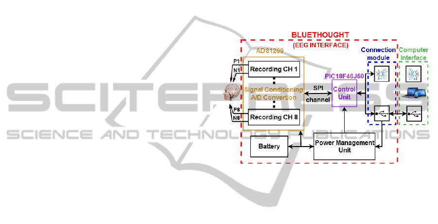
2 SYSTEM ARCHITECTURE
The designed system, named BlueThought by joining
the implemented transmission link with the nature of
the acquired signals, is based on a differential 8 chan-
nel recording unit. The EEG signals detected with a
standard EEG cap are first amplified and then con-
verted into digital signals by an ADS1299 component
from Texas Instrument. Once acquired, digital sig-
nals are transmitted to a remote back-end by means
of a Microchip Bluetooth RN-42 module. Moreover a
USB connection was introduced to charge the EEG
recorder battery and as additional channel for data
transfer. A Microchip PIC18F46J50 coordinates data
exchange between ADC and BT or USB external con-
troller. The system architecture is depicted in Fig.1.
Figure 1: BlueThought: System Architecture.
In addition a power management unit generates
all digital and analog voltage supplies for the ADC,
the microprocessor and the BT transceiver from a
3.7V − 950mAh LiPo battery. Even the battery charg-
ing circuit was implemented on the board. The EEG
recorder was realized on the 5.5cmX3.5cm double
face board depicted in Fig.2. In the following further
details on the main modules of the EEG recorder will
be described.
2.1 Signal Conditioning and Digital
Conversion
Before being converted into digital format, the input
signals are filtered and amplified. To reduce power
consumption and PCB area we decided not to insert
an additional signal conditioning block but to use the
one provided by the A/D converter (ADS1299). This
device contains eight independent differential chan-
nels allowing simultaneous acquisition. An internal
multiplexer allows to select the P and N input sig-
nals among various sources and depending on the
selected signals different recording modes are possi-
ble: normal recording, test and impedance monitor-
ing mode. The normal recording mode is the default
working set-up in which EEG signals are acquired in
both single-ended and differential configuration. In
BIODEVICES2015-InternationalConferenceonBiomedicalElectronicsandDevices
30
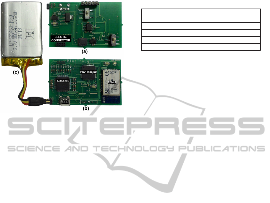
Figure 2: EEG Interface prototype: power management
circuit on bottom side(a); ADS1299 (ADC), PIC18F46J50
(microprocessor), USB and RN-42 (BT transceiver) on top
face(b) and a 3.7V − 950mAh LiPo battery(c).
single-ended measurements the N signals are inter-
nally shorted to the external reference (typically mid-
supply voltage) or to the bias signal generated by the
internal bias module on the base of a desired input
signal combination. Whereas in differential measure-
ments both P and N signals come from the EEG cap.
To reduce the number of interconnectionsbetween the
EEG recorder and the bonnet all N input lines are
shorted together getting only one common reference
electrode conveniently placed on the patient body. In
test mode, different internally-generated test signals
can be selected as input allowing the signal acquisi-
tion chain to be tested out. Another important feature
provided by the ADS1299 is the lead-off detection. It
consists in a continuous patient electrode impedance
monitoring to verify if a suitable connection is present
or not.
The first stage of each acquisition channel is a
differential low-noise programmable gain amplifier
(PGA). It offers seven gain settings (1,2,4,6,8,12, and
24) that can be set-up by writing the channel-setting
registers (one per channel) of the ADS1299. As men-
tioned in Sec.1, our EEG recorder can acquire sig-
nals with a bandwidth wider then standard EEG mon-
itor. In fact, as reported in Tab.1, the system supports
different sample rates from 250SPS up to 2000SPS
resulting in a maximum bandwidth of 524Hz. This
makes our device suitable for a wide range of ap-
plications even those requiring the analysis of sig-
nals out of standard EEG frequency. After being
amplified, the signal is digitalized by a 24-bit sigma
delta converter. The ADC operates in two different
modes: continuous mode (default) and single-shot
Table 1: EEG Recorder Output Data Rate and -3dB BW.
OUTPUT DATA RATE -3dB BANDWIDTH
(SPS) (Hz)
250 65
500 131
1000 262
2000 524
mode. In the first modality, when a start command
is sent, it continuously converts the input signal. The
conversion ends when a stop command is received.
Whereas, if the device is in single-shot mode it gen-
erates only one sample per received start command.
This means that to begin a new conversion, a new
start command has to be sent. Regardless of the op-
erating mode, as a single sample conversion ends, a
data-ready signal (DRDY) is pulled down to notify
the microprocessor that a new sample is ready. Af-
ter being converted, the eight samples (each per chan-
nel) are packed and sent to the micro-controller over
a 3MHz SPI connection. Each data packet contains
24-bit of header and 216-bit of sampled data. In the
following the control unit is described. It forwards the
samples received from the ADC to the BT transceiver
or to the USB controller depending if a wireless or a
wired connection is being used.
2.2 Control Unit
The Microchip PIC18F46J50 is used as control unit
to serve two main tasks: system set-up and data ex-
change. The PIC is powered at 3.3V with a CPU clock
frequency of 48MHz generated by an on-chip oscilla-
tor. At system power-up, the PIC is used to setup the
EEG interface defining both recordingand connection
parameters such as acquisition gain and bandwidth,
ADC SPI clock frequency, BT data rate and commu-
nication protocol parameters. All values are tuned to
find a good compromise between the acquired EEG
signal quality and the power consumption. Once that
the system started to acquire the EEG signals, the con-
trol unit coordinates data exchange among the con-
verter and BT or USB remote back-end.
The microprocessor provides several internal pe-
ripherals that, if not used, can be disabled to save
power. In particular we are interested in using the
USB and the UART in/out ports to respectively con-
nect the PIC to a remote USB controller or to the BT
transceiver.
Although the system communication mode can be
on-line modified by the user, if, on power-up, any
device is connected to the USB port, the PIC auto-
matically enables the USB controller otherwise the
AWide-bandandUser-friendlyEEGRecordingSystemforWearableApplications
31
BT transceiver is turned on. Once defined the con-
nection mode, the microprocessor starts a polling cy-
cle waiting for data coming from the remote con-
troller. The received commands are decoded and ex-
ecuted. Such commands, generally are aimed at con-
trolling the ADC or the BT transceiver but they can
also be addressed to the same microprocessor for ex-
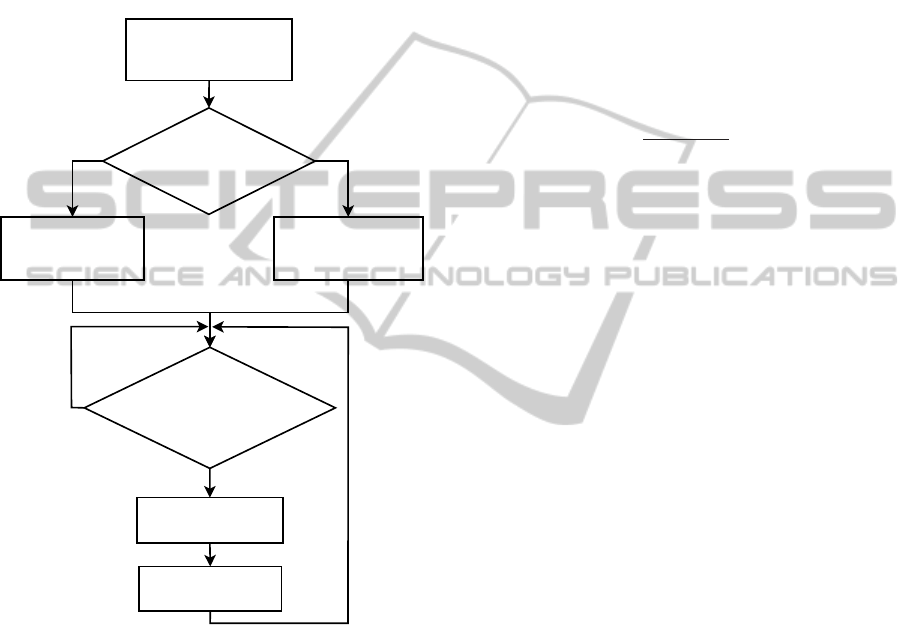
ample to setup the USB controller. The main steps
of the firmware are described in the flow chart of
Fig.3. Regardless of the back-end connection mode
Initialize PIC & ADC
with default settings
Is any USB device
connected ?
Initialize USB controller
with default settings
Initialize Bluetooth
with default settings
No
Yes
Has been any command
received ?
No
Decode command
Execute command
Yes
Figure 3: Main steps of the control unit firmware.
(via USB or BT) and only in single-shot recording,
the same polling cycle is used by the PIC to send
the sampled data to the remote controller. Other-
wise, in continuous recording, sampled data transmis-
sion is handled by an interrupt service routine. The
ADS1299 data-ready signal (DRDY) is connected to
an interrupt sensitive pin of the PIC acting as an ex-
ternal interrupt. When DRDY is pulled down (i.e.
new samples are available) an exception is raised and
the interrupt service routing is executed. The new
samples are transferred from the ADC to the micro-
processor that forwards data to the remote controller.
Some details about the USB and the BT connection
are given in the following paragraph.
2.3 Data Transmission
In normal operation mode, the BT transceiver allows
wireless data transmission between the EEG recorder
and the remote back-end, whereas the USB controller
is used for battery recharging. However, during test
mode, the wired connection can be used for both
data transfer and system powering. Enabling high
frequency EEG recording, the ADC needs to oper-
ate at sample frequencies up to 2000SPS (see Tab.1)
resulting in a maximum outputs data rate (ODR) of
54Kbyte/sec (Eq.1). This is a critical parameter to
define the data-exchange channel specifications.
Single data packet: 216bit
ODR(@2000SPS):
2000∗ 216
8
= 54Kbyte/sec
(1)
The USB port is directly handled by an on-chip USB
controller and can operate in two different modali-
ties: CDC and HID mode. To make the USB suit-
able for our application, a standard HID protocol was
implemented. Working at full speed (48MHz) with
64-byte data packet size, the data transfer speed is
limited to 64Kbytes/sec. In addition, to make the
transmission more efficient, two sampled data pack-
ets (2x216bit = 432bit) are grouped in the same USB
frame. As a result, in worst conditions (2000SPS), the
required data transfer rate amounts to 27Kbyte/sec
that is below the USB transfer rate limit.
In contrast to the USB HID protocol, the BT
transceiver does not require fixed size packets, but
their length is adapted to the amount of transferred
data. The RN-42 is a small form factor, low power,
class 2 BT radio with on-chip antenna. It delivers up
to a 3Mbps data rate for distances up to 20 meters.
It uses an UART port to communicate with the con-
trol unit and operates in two modes: data mode (de-
fault) and command mode. In data mode, the module
works as a data pipe. When the module receives data,
it strips the BT headers and forwards the data to the
UART port. When data is written to the UART port,
the module constructs the BT packet and sends it out
over the BT wireless connection. Thus, the entire pro-
cess of sending/receiving data to the host is transpar-
ent to the PIC. The command mode is used to defin-
ing the BT operating mode, the UART baud rate and
others control flow parameters. Moreover the RN-42
operates in slave mode so that other BT devices (PC,
tablet or smartphone) can discover and connect to the
module.
BIODEVICES2015-InternationalConferenceonBiomedicalElectronicsandDevices
32
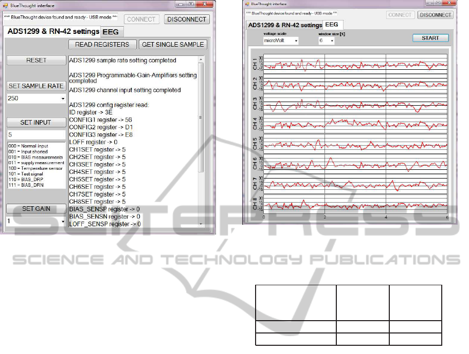
Figure 4: Visual C++ EEG interface: system setup window.
3 REMOTE INTERFACE
The designed system is a general purpose EEG
recorder and depending on the treated pathology a
specific software can be developed. At this first stage
of the project a Visual C++ application was written,
implementing only the essential features for the hard-
ware debugging. The ADC module can be completely
configured in terms of PGA gain and sample rate and
both continuous and single-shot modes are selectable.
The eight recorded signals are plotted for a real-time
view and stored in a text file for off-line data com-
puting. Fig.4 and Fig.5 show the two main window
of the developed interface. The first refers to the sys-
tem settings and the second to the plotting of the eight
recorded signals. For all channels is possible to setup
the amplitude scale (µV, mV or V) and the temporal
window size.
4 RESULTS
All system features were first characterized and than
compared with a standard laboratory equipment. To
start with its static electrical characterization, Tab.2
collects the EEG interface power consumption in dif-
ferent working conditions. In idle state (only the mi-
croprocessor is on) it has a minimum power consump-
tion of about 119mW whereas in worst conditions (i.e.
all devices are on, sample rate of 2000SPS and ac-
tive BT data transmission) it absorbs a maximum of
Figure 5: Visual C++ EEG interface: on-line plotting win-
dow in a µV amplitude scale and with a 6s temporal window.
Table 2: EEG Recorder Power Consumption in different
working conditions.
Power A/D A/D
Consumption Converter Converter
(mW) (OFF) (ON)
Bluetooth (OFF) 119 158
Bluetooth (ON) 230 270
270mW. Under this conditions and with the chosen
battery (3.7V − 950mAh LiPo) the system can contin-
uously work for about 13 hours. Further experiments
were performed to study the dynamic behaviour of the
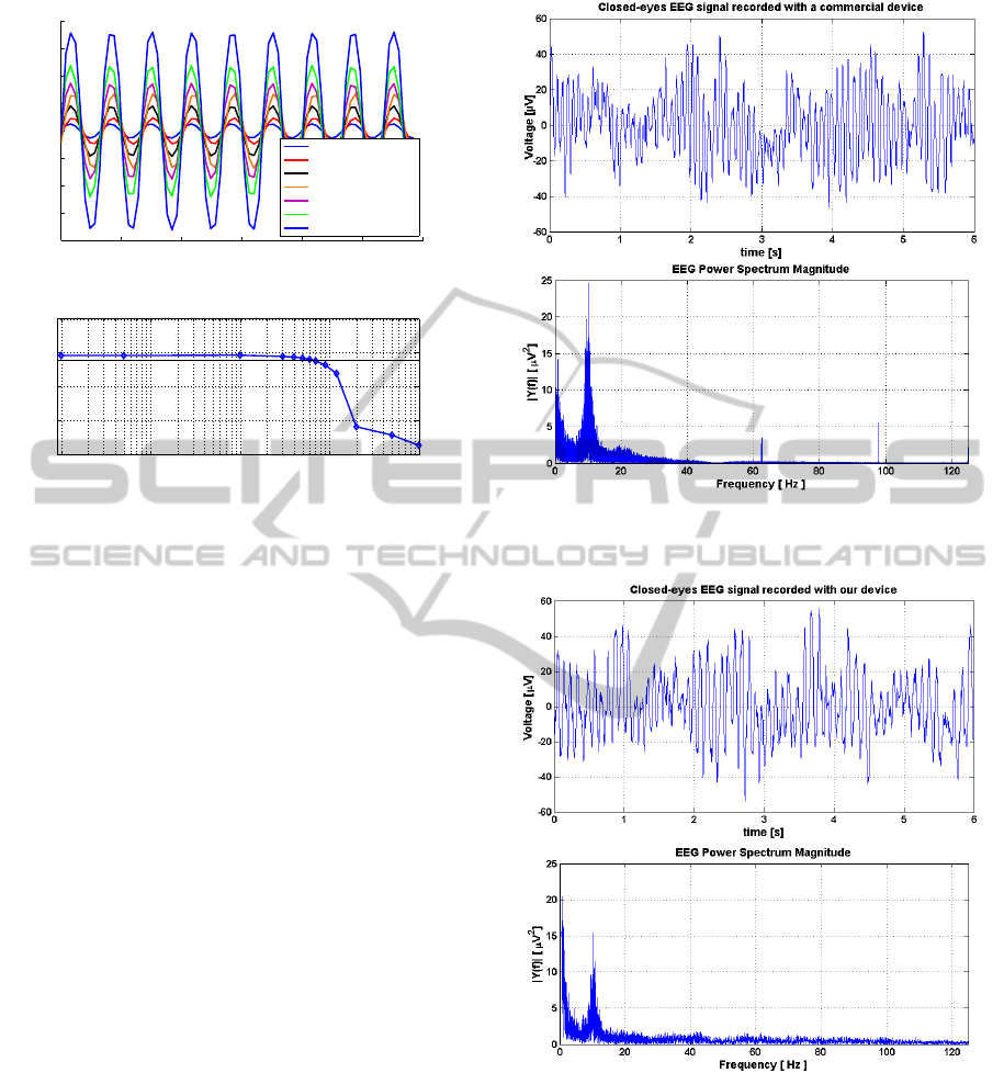
EEG acquisition channel. Its gain programmability
from 1V/V up to 24V/V was confirmed acquiring a
12mV − 30Hz sine as depicted in the above plot of
Fig.6. The device showed a 63.5Hz −3dB bandwidth
at sample rate of 250SPS and the magnitude bode di-
agram of the recording channel transfer function is
depicted in Fig.6 (below plot). Moreover both wired
(USB) and wireless (BT) connections were tested.
Once the system main functions have been proved,
some in-vivo EEG measurements, on one human sub-
ject, were performed. To evaluate the signal quality of
the designed EEG recorder, the system was compared
with a commercial device (Brain QUICK,(Micromed,
2014)) depicted in Fig.9 where the huge difference
in terms of dimensions between the two devices is
also highlighted. Moreover, the experimental setup,
depicted in Fig.10, includes a commercial EEG cap
(KIT-CAP-SPEXT61 from Micromed) with 61 elec-
trodes used to acquire the neural signals.
To better compare the two devices, they were
AWide-bandandUser-friendlyEEGRecordingSystemforWearableApplications
33
0 5 10 15 20 25 30
−200
−150
−100
−50
0
50
100
150
200
time [ms]
Voltage [mV]
PGA Gain test (input signal: sine, f=30Hz, Vmax=12mV)
G=1, Vmax =12.5mV
G=2, Vmax=24mV
G=4, Vmax=46mV
G=6, Vmax=68mV
G=8, Vmax=87mV
G=12, Vmax=120mV
G=24, Vmax=180mV
10
−1
10
0
10
1
10
2
10
3
−40
−20
0
20
40
EEG Acquisition Channel −3dB Bandwidth at 250SPS
Frequency [Hz]
Magnitude [dB]
Figure 6: The EEG interface gain programmability vali-
dated recording a 12mV − 30Hz sine at 250SPS (on the top)
and the system -3dB bandwidth (63.5Hz) at 250SPS (on the
bottom).
connected to adjacent electrodes and simultaneous
recordings were performed in different patient con-
ditions. During the first test, the human subject was
in resting state with closed eyes to avoid any kind of
artifact. Fig.7 and Fig.8 show the EEG signals re-
spectively acquired by the Brain Quick and by our
EEG recorder. The signals recorded at 250SPS are
quite similar in both time and frequency domains. In
Fig.11 it is possible to appreciate the differences be-
tween an open-eyes (on the left) and a closed-eyes (on
the right) EEG signal perfectly recorded by our device
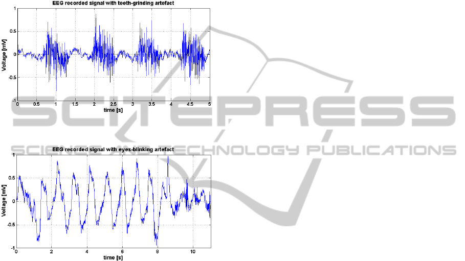
at 250SPS. Finally, to further validate our system,
some typical EEG artifacts such as the teeth-grinding
signal (Fig.12) and the eyes-blinking effect (Fig.13)
were recorded. They respect the typical shapes and
amplitudes of such signals.
5 CONCLUSIONS AND
DISCUSSION
An off-the-shelf based EEG interface was presented.
It is a wearable system that, thanks to its small di-
mensions (height: 5.5cm x width: 3.5cm x depth:
1.0cm), can be easily placed on the patient head and
integrated with the electrodes framework. The devel-
oped device has 8 independent acquisition channels
and was designed with the aim of being user-friendly
and suitable for all applications in which a contin-
Figure 7: Closed-eyes EEG signal, in time and frequency
domain, recorded at 250SPS by Micromed Brain QUICK
(Micromed, 2014).
Figure 8: Closed-eyes EEG signal, in time and frequency
domain, recorded by our device at 250SPS.
uous EEG monitoring is required. In fully working
condition (i.e. when acquiring and transmitting data)
the system exhibits an overall power consumption of
270mW. Even-though it is higher than of other sys-
tems (Tab.3), the device allows 13 hours of continu-
ous signal recording that is in line with other wearable
devices. The higher power consumption is mainly
due to the choice of using a COTS solution and a BT
link to connect a remote controller. However it gives
BIODEVICES2015-InternationalConferenceonBiomedicalElectronicsandDevices
34
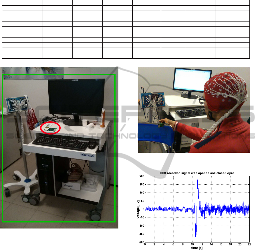
Table 3: Comparison between some state-of-the-art EEG Recorders.
Our device Quasar Imec Emotiv Epoc NeuroSky Brown L. Enobio
CMRR > 110dB > 120dB 115dB
Input Impedance 1GΩ 47GΩ
Bandwidth 0.01− 524Hz 0.02− 120Hz 0.3− 100Hz 0.2− 45Hz 3− 100Hz 0.5− 375Hz 0− 250(500)Hz
Channel number 8 12 12 14 1 8 8− 20(32)
Noise < 2µVpp 3µVpp 4µVpp 1µVpp < 1µVrms
Bit number 24 16 12 16 11 24
Wireless protocol BT Proprietary Nordic RF Proprietary BT Proprietary BT
Power consumption 270mW 42mW 130mW 12mW
Run time 13h 24h 12h 10h 30h 16h
Technology COTS ASIC / COTS ASIC / COTS
Figure 9: Comparison between our wearable EEG interface
(red circle) and a cumbersome commercial device (green
box).
the device the great advantage to easily connect any
BT-based end-terminal in contrast to other systems
that, using a proprietary wireless link, require specific
hardware. Moreover, compared to others state-of-the-
art equipments, our EEG recorder has a wider band-
width, up to 524Hz, allowing high-frequency EEG
monitoring. This can be very useful to deeper under-
stand and investigate a certain number of pathologies.
In addition, a Windows-based Visual C++ software
was written for the EEG recorder testing purpose. The
system was completed validated by in-vivo measure-
ments on human patient and compered with a com-
mercial laboratory equipment.
Moving towards a device that can easily become
part of everyday life for all people improving their
Figure 10: Experimental setup for in-vivo EEG measure-
ments.
Figure 11: EEG recorded signal with opened-eyes (on the
left) and closed-eyes (on the right).
living conditions from both health and entertainment
points of view and with the least economical and
daily-activity impact is our main goal. Therefore, be-
ing a wearable device, next developments are the re-
duction of the power consumption and the develop-
ing of smartphone-based application to respectively
increase the battery life and to make the system com-
pletely portable. In particular, some future improve-
ments include the use of a new generation BT called
Bluetooth 4.0 Low Energy (BTLE) that drastically re-
duce the power transmission and a review of the con-
trol unit strategy turning off, time by time, all on-
AWide-bandandUser-friendlyEEGRecordingSystemforWearableApplications
35
board unused devices. Moreover the possibility to op-
tionally expand the number of input channels by plug-
ging in an additional acquisition module and the intro-
ducing of on-board data storage capabilities might be
considered. Finally, a custom chip solution for sig-
nal conditioning and converting will might be investi-
gated to further reduce both power consumption and
system dimensions.
Figure 12: EEG recorded signal with teeth-grinding arti-
facts.
Figure 13: EEG recorded signal with eyes-blinking arti-
facts.
ACKNOWLEDGEMENTS
The authors would like to thank Dr. Matteo Fraschini
and Matteo Demuru from the University of Cagliari
for their support on EEG recording in-vivo experi-
ments. L. Bisoni gratefully acknowledges Sardinia
Regional Government for the financial support of his
PhD scholarship (P.O.R. Sardegna F.S.E. Operational
Programme of the Autonomous Region of Sardinia,
European Social Fund 2007-2013 - Axis IV Human
Resources, Objective l.3, Line of Activity l.3.1.).
REFERENCES
A. Riera, S. Dunne, I. C. G. R. (2008). Starfast: a wireless
wearable eeg/ecg biometric system based on the eno-
bio sensor. Proceedings of the International Workshop
on Wearable Micro and Nanosystems for Personalised
Health (pHealth08).
Alonso J., Angermeyer MC., B. S. e. a. (2004). Prevalence
of mental disorders in europe: results from the euro-
pean study of the epidemiology of mental disorders
(esemed) project. Acta Psychiatrica Scandinavica,
109:21–27.
Brown L., Van de Molengraft J., Y. R. T. T. e. a. (2010). A
low-power, wireless, 8-channel eeg monitoring head-
set. Engineering in Medicine and Biology Society
(EMBC), 32
n
d Annual International Conference of
the IEEE EMBS:4197–4200.
Carmo J.P., Dias N.S., S.H.M.P. e. a. (2007). A 2.4-ghz low-
power/low-voltage wireless plug-and-play module for
eeg applications. Sensors Journal,7:1524–1531.
Chan S.R., Torous J., H. L. and P., Y. (2014). Mobile tele-
mental health: Increasing applications and a move to
hybrid models of care. Healthcare, 2(2):220–233.
El Khaddar, M., Harroud, H., Boulmalf, M., ElKoutbi, M.,
and Habbani, A. (2012). Emerging wireless technolo-
gies in e-health trends, challenges, and framework
design issues. Multimedia Computing and Systems
(ICMCS), 2012 International Conference on, pages
440–445.
Emotiv (2013). http://emotiv.com.
J. Olesen, A. Gustavsson, M. S. H.-U. W. e. a. (2012). The
economic cost of brain disorders in europe. European
Journal of Neurology, 19:155–162.
Lin, C.-T., Ko, L.-W., Chiou, J.-C., Duann, J.-R., Huang,
R.-S., Liang, S.-F., Chiu, T.-W., and Jung, T.-P.
(2008). Noninvasive neural prostheses using mo-
bile and wireless eeg. Proceedings of the IEEE,
96(7):1167–1183.
Lupu, C. and Cosmin-Constantin, M. (2013). Actual
portable devices as base for telemedicine and e-health:
Research and case study application. E-Health and
Bioengineering Conference (EHB), 2013, pages 1–4.
Micromed (2014). Brain quick. http://www.micromed.eu.
Mihajlovic, V., Grundlehner, B., Vullers, R., and Penders, J.
(2014). Wearable, wireless eeg solutions in daily life
applications: What are we missing? Biomedical and
Health Informatics, IEEE Journal of, PP(99):1–1.
NeuroSky (2009). http://neurosky.com.
Patki, S., Grundlehner, B., Verwegen, A., Mitra, S., Xu,
J., Matsumoto, A., Yazicioglu, R., and Penders, J.
(2012). Wireless eeg system with real time impedance
monitoring and active electrodes. Biomedical Circuits
and Systems Conference (BioCAS), 2012 IEEE, pages
108–111.
Quasar (2013). http://www.quasarusa.com.
Sapal Tachakra, X.H. Wang, R. S. I. and Song, Y.
(2003). Mobile e-health: The unwired evolution of
telemedicine. Telemedicine Journal and e-Health,
9(3):247–257.
Smith, A. (2013). Smartphone ownership 2013.
Pew Research Center, http://www.pewinternet.org
/2013/06/05/smartphone-ownership-2013/.
Waterhouse, E. (2003). New horizons in ambulatory elec-
troencephalography. Engineering in Medicine and Bi-
ology Magazine, 22:74–80.
BIODEVICES2015-InternationalConferenceonBiomedicalElectronicsandDevices
36
