
Development of an Emergency Braking System for Teleoperated Vehicles
Based on Lidar Sensor Data
Johannes Wallner, Tito Tang and Markus Lienkamp
1
Institute of Automotive Technology, Technische Universit
¨
at M
¨
unchen, Boltzmannstr. 15, 85748 Garching b. M
¨
unchen,
Germany
Keywords:
Emergency Braking System, Teleoperated Vehicles, Lidar Sensor Raw Data, Particle Filter, Motion Prediction.
Abstract:
A lidar-based approach of an emergency braking system for teleoperated vehicles is presented. Despite the
time delay for the communication link of a teleoperated system, the vehicle has to be able to react to emerging
objects in time. Starting with intelligent sensor data processing, reliable information is computed. An adapted
particle filter algorithm tracks moving points to calculate their mean velocity, used for the prediction of sur-
rounding moving objects. Further, in order to interpret this information, a situation assessment based on an
intervention concept derived from Kamm’s circle is implemented. A motion prediction of possible trajectories
of the ego-vehicle results in a clear decision-making process. All calculations are made at the raw data level
and can be done online. Through artificial objects being included in real sensor data, the methodology was
validated.
1 INTRODUCTION
In the case of teleoperated vehicles an operator re-
places the real driver. Teleoperated driving is consid-
ered to be an intermediate step towards permanently
increasing automation of vehicles. Due to the human
operator, more complex traffic situations than in fully
automated systems can be managed (Diermeyer et al.,
2011). One of the challenges is the time delay for the
communication link between the operator and the ve-
hicle, which impedes a fast reaction compared to a
normal attentive driver. To guarantee a safety level
comparable to normal driving, the vehicle must be
equipped with an automatic emergency braking sys-
tem to avoid collisions. Further information on tele-
operated road vehicles and the system design for such
a vehicle can be found in (Chen et al., 2007) (Ware
and Pan, 2011) (Tang et al., 2013) (Gnatzig et al.,
2013).
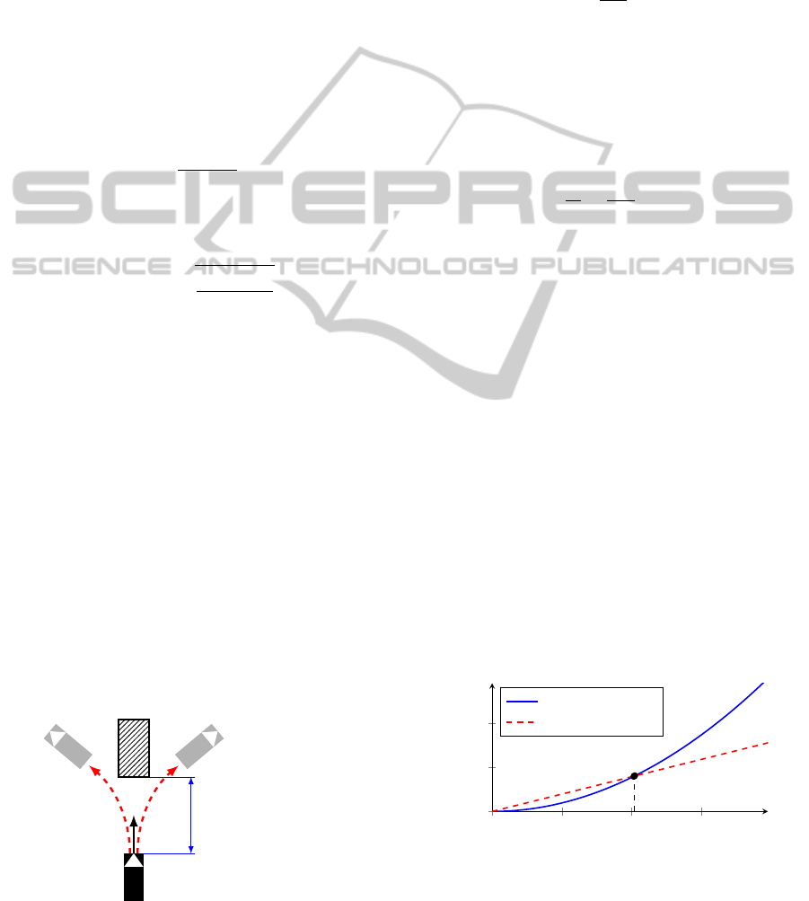
The test vehicle, an AUDI Q7, is equipped with a
lidar sensor in the front, as shown in Figure 1. The
following approach is characterized by the exclusive
usage of the data of this sensor. The reflection points
are the only input of the braking system. The output is
a decision whether emergency braking is required or
not. This approach could also be used in autonomous
driving vehicles and has low requirements on the sen-
sor configuration.
Figure 1: Operating mode of the lidar sensor.
2 STATE OF THE ART
2.1 Categorization on Basis of
Specifications
There are already existing automatic emergency brak-
ing systems on the market. A categorization into three
different types is made on the basis of specifications:
Forward collision warning, which detects a potential
collision and warns the driver, Collision Mitigation
Braking System (CMBS), which detects a potential
collision and applies an emergency brake automati-
cally when the collision has become inevitable, and
collision avoidance, which can take action to fully
avoid a potential collision (Grover et al., 2013, p. 1).
569
Wallner J., Tang T. and Lienkamp M..
Development of an Emergency Braking System for Teleoperated Vehicles Based on Lidar Sensor Data.
DOI: 10.5220/0005114905690576
In Proceedings of the 11th International Conference on Informatics in Control, Automation and Robotics (ICINCO-2014), pages 569-576
ISBN: 978-989-758-040-6
Copyright
c
2014 SCITEPRESS (Science and Technology Publications, Lda.)
2.2 Intervention Strategies
Based on specifications of an emergency braking sys-
tem the intervention strategy depends on the brak-
ing deceleration, instant of time for braking and
initial velocity. The strategy here was presented
first by KOPISCHKE and shown amongst others in
(K
¨
ampchen, 2007, p. 189), (Jansson et al., 2002),
(Hong et al., 2008) and (St
¨
ampfle and Branz, 2008,
p. 13). The basis of this strategy is a vehicle with the
velocity v
ego
heading for a static obstacle, illustrated
in Figure 2.
A constant deceleration a
brake
results in a brak-
ing distance d
brake
depending on the ego velocity v
ego
where a collision can be avoided successfully:
d
brake
=
v
2
ego
2 ·a
brake
. (1)
The minimum distance for an obstacle avoidance
maneuver with a constant lateral acceleration a
y
is:
d
avoid
= v
ego
·
s
w
ego
+ w
ob
a
y
, (2)
where w
ego
and w
ob
are the widths of the ego-vehicle
and the obstacle.
Calculating the distances d
brake
and d
avoid
as a
function of the ego velocity v
ego
leads to the diagram
in Figure 3. It is obvious that up to a velocity v
crit
a
collision can be avoided by braking exclusively.
3 SENSOR DATA PROCESSING
The SICK LMS291-S05 lidar sensor of the test ve-
hicle samples the environment with 181 measurement
points at a frequency of f = 75 Hz. To reduce the total
amount of points that need to be checked, filtering is
essential. Measurement points of static and dynamic
objects are filtered separately.
v
ego
braking distance
.
Figure 2: Test scenario with an ego-vehicle heading for a
static obstacle.
3.1 Filtering of Static Objects
The filtering for static objects bases on the area that
can be reached with vehicle dynamics (Schmidt et al.,
2005). Assuming a constant velocity v
ego
and a con-
stant lateral acceleration a
y
, a vehicle moves on a cir-
cular path with radius r:
r =
v
2
ego
a
y
. (3)
The distance of the segment of a circle d
c
that is
driven over in a period of time ∆t is
d
c
= v
ego
· ∆t. (4)
For variable lateral accelerations the angle for
each segment of a circle calculates as follows:
γ =
d
c
r
=
a
y
v
ego
· ∆t. (5)
The endpoints of these trajectories result in an area
that can be reached with vehicle dynamics with con-
stant lateral acceleration. This area is shown exem-
plary for v
ego
= 9
m
/s and ∆t = 5s in Figure 4. Every
(static) measurement point outside of this area is fil-
tered out to reduce computational effort.
3.2 Filtering of Dynamic Objects
3.2.1 Detection of Dynamic Points
The detection of dynamic points is achieved by a dy-
namic threshold operation. Assuming a minimum
speed for dynamic objects of v
min
their measurement
points have to be moved during one time step dt for
at least
d
min
= v
min
· dt. (6)
Only points moving fast enough are passed on to the
next step.
0 20 40
60
0
10
20
v
crit
≈ 40.7
km
/h
Velocity [
km
/h]
Distance [m]
braking distance
avoiding distance
Figure 3: Braking distance and avoiding distance as a func-
tion of the initial ego velocity for a
y
= 8
m
/s
2
, a
brake
= 8
m
/s
2
,
w
ego
= 2 m and w
ob
= 2 m, see (St
¨
ampfle and Branz, 2008,
p. 13) (Jansson et al., 2002).
ICINCO2014-11thInternationalConferenceonInformaticsinControl,AutomationandRobotics
570
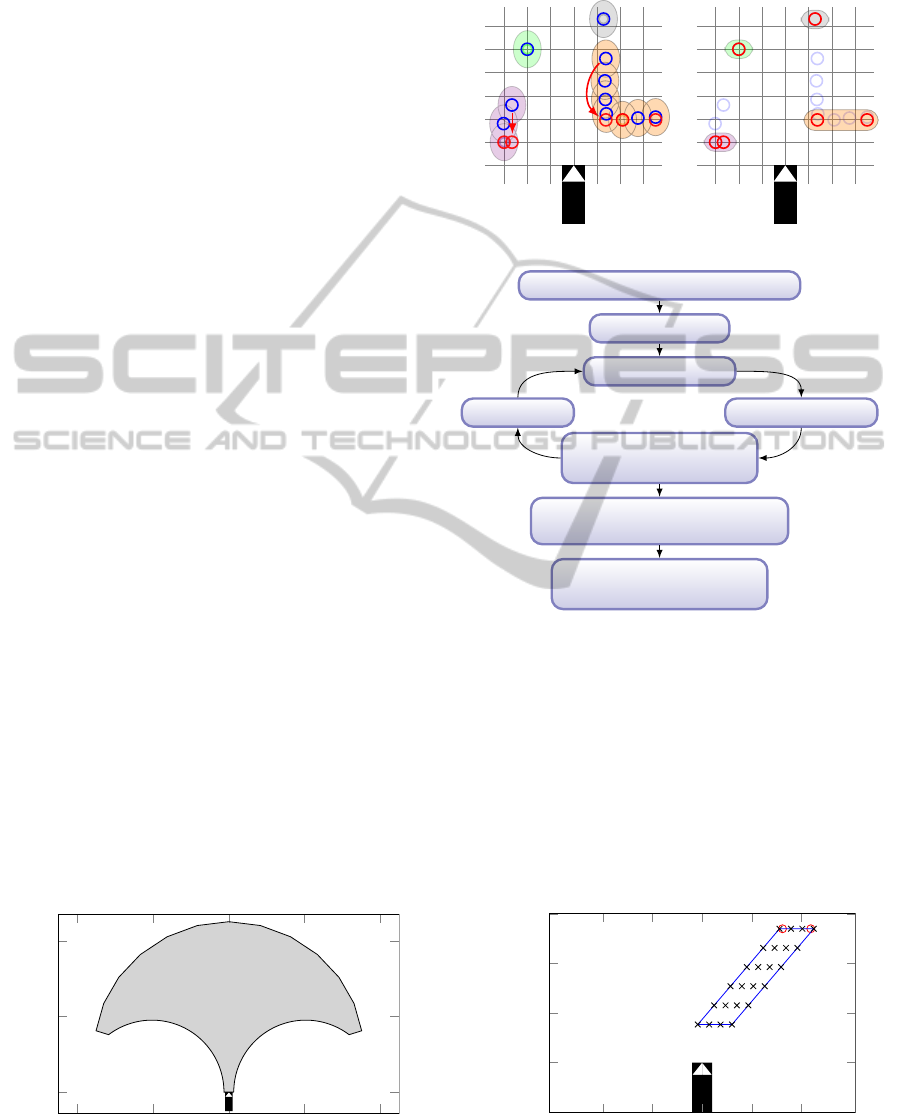
3.2.2 Grouping and Selection
To reduce the number of moving points even more the
points are grouped. The longitudinal and the lateral
distance between two points is weighted differently,
the threshold depends on the distance like in (Thuy
and Puente Leon, 2009) and the maximum size of one
group of points is limited.
After the grouping step just two points of each
group are selected: therefore the two points of the lat-
eral edge of each group are moved to the minimum
longitudinal distance of this group. Thus the move-
ment of the underlying object is represented robustly.
The steps of grouping, translation and selection are
shown in Figure 5. It is obvious that if the point at
the top right is grouped with the right object in a later
time step, what is quite plausible, the selected points
of the right object won’t move that much. It is there-
fore easier to track them in the following step.
3.3 Particle Filter
To track the selected dynamic points from the last
subsection an adapted particle filter is used. For a the-
oretical background of particle filters for tracking ap-
plications, see e.g. (Almeida and Araujo, 2008) (Ris-
tic et al., 2004). The approach here is summarized in
Figure 6.
Each particle is modeled by an underlying con-
stant velocity movement model. With the steps pre-
diction, computing weights and a resampling step, re-
alized with an algorithm from (Thrun, 2013), it is pos-
sible to get reliable information about the amount and
direction of the velocity of objects.
After sorting all particles according to their
weights, an amount p of the best particles is chosen
and a mean velocity for each dynamic object is calcu-
lated. The result is a predicted direction of motion of
dynamic objects exemplary illustrated for t
predict
= 2 s
in Figure 7.
−40 −20 0 20 40
0
20
40
[m]
[m]
Figure 4: Relevant area for sensor data filtering.
Unprocessed Measurement
Grouping and translation to
the nearest point of each group
Processed Measurement
Selected points
of each group
Figure 5: Grouping and selection of points.
Including Ego Motion in Sensor Data
Creating Particles
Predicting Particles
Weighting ParticlesAdding Noise
Weighted Drawing from
an Urn with Replacement
Sorting According to the Weight
and Selection of the Best Particles
Calculation of the Average
Velocity per Grouped Points
Figure 6: Overview of the particle filter algorithm.
4 SITUATION ASSESSMENT AND
BRAKING DECISION
4.1 Intervention Concept
The intervention concept is defined by a range of pos-
sible accelerations, which is provided to the operator.
−10 −5 0 5 10
−5
0
5
10
15
[m]
[m]
Figure 7: Prediction of a moving object.
DevelopmentofanEmergencyBrakingSystemforTeleoperatedVehiclesBasedonLidarSensorData
571
−6
−4 −2 0 2 4
6
−4
−2
0
2
4
6
8
Lateral Acceleration [
m
/s
2
]
Longitudinal Acceleration [
m
/s
2
]
range of 95% of drivers
(Hackenberg and Heißing, 1982)
acceleration range (Biral et al., 2005)
acceleration range
(Wegscheider and Prokop, 2005)
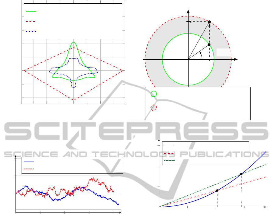
Figure 8: Exemplary acceleration ranges for normal driving
situations .
0 10 20 30 40
−2
0
2
4
Time [s]
Lateral Acceleration a
y
[
m
/s
2
]
a
y
- test run on 2012/06/17 at 10:06:25
a
y
- test run on 2012/06/17 at 10:15:33
Figure 9: Lateral acceleration in speed range of city traffic
during test run.
Usually normal drives take place in specific accele-
ration ranges. Some exemplary acceleration ranges
for normal driving situations of different studies are
shown in Figure 8.
A test run with the experimental vehicle in speed
ranges of city traffic shows similar results. All accel-
erations remain within an interval of [−2,2]
m
/s
2
, as
can be seen in Figure 9. These plotted test runs were
carried out in normal drive mode, but teleoperated ve-
hicles are limited to a maximum lateral acceleration
of |2
m
/s
2
|. Therefore, this approach is applicable.
In this specific application of teleoperated vehi-
cles, an acceleration range up to |a
max
| = 4
m
/s
2
is pro-
vided to the operator. This method is based on the
principle of Kamm’s circle, summarized in Figure 10.
If a potential collision cannot be avoided within the
green circle from the operator, the emergency braking
system intervenes and brakes automatically within the
Longitudinal Acceleration [
m
/s
2
]
Lateral Accelerati
Lateral Acceleration
[
m
/s
2
]
Maximum provided acceleration range
of the operator
Minimum estimated acceleration range
of the emergency braking system
a
avoid
a
EB
ϕ
a
EB,min
Figure 10: Principle of the intervention concept based on
Kamm’s circle.
0 20 40
60
0
10
20
30
v
crit
≈ 40.7
km
/h
v
crit,tel
≈ 57.6
km
/h
Velocity [
km
/h]
Distance [m]
braking distance
avoiding distance
avoiding distance (teleoperated)
Figure 11: Speed range of full collision avoidance of the
emergency braking system.
minimal estimated acceleration range in the red circle.
With a supposed emergency braking decelera-
tion a
EB,min
= 8
m
/s
2
and a lateral avoiding maneu-
ver acceleration a
y
= 4
m
/s
2
, the intervention of the
presented emergency braking system occurs earlier.
Therefore the critical velocity of Figure 3 rises up to
v
crit,tel
≈ 57.6
km
/h where collisions can be avoided
successfully, illustrated in Figure 11. The value of
a
EB,min
= 8
m
/s
2
is chosen intentionally low in case of
varying friction coefficients.
4.2 Motion Prediction of the
Ego-Vehicle by Trajectories
Combining all possible lateral and longitudinal accel-
erations in Figure 10 by varying ϕ yields to emer-
gency braking trajectories that offer the opportunity
to predict the motion of the ego-vehicle in case of
a braking maneuver. The length of these emergency
ICINCO2014-11thInternationalConferenceonInformaticsinControl,AutomationandRobotics
572

−5
0
5
−5
0
5
[m]
[m]
(a) v
ego
= 4
m
/s
−5
0
5
−5
0
5
[m]
[m]
(b) v
ego
= 8
m
/s
Figure 12: Motion prediction by trajectories.
braking trajectories d
EB
, respectively the braking dis-
tance with constant lateral acceleration, is
d
EB
=
v
2
ego
2 · a
EB
. (7)
The trajectories for an emergency braking decel-
eration a
EB,min
= 8
m
/s
2
and a maximum lateral accel-
eration of a
y,max
= 4
m
/s
2
are shown exemplary for two
different velocities in Figure 12.
For teleoperated vehicles there is a possibility to
limit the number of trajectories to the one already cho-
sen by the operator. The big benefit of a motion pre-
diction of the ego-vehicle by trajectories is that the
whole decision making process as to whether emer-
gency braking is required is simplified and these tra-
jectories just have to be checked for trafficability.
4.3 Decision-Making Process.
The decision-making process distinguishes between
drivable and occupied trajectories. If all trajectories
are occupied over a certain time period, emergency
braking is triggered. In Figure 13(a) some trajecto-
ries are occupied, but because of the existing possi-
bility to avoid the obstacle, no emergency braking is
required. The situation in Figure 13(b) is different,
where no avoiding or braking maneuver in the accel-
eration range of the operator can avoid the collision.
Therefore in this case the emergency system would
trigger a braking action.
5 VALIDATION WITH REAL
SENSOR DATA
5.1 Generation of Artificial Objects in
Real Sensor Data
To validate the presented system, artificial objects
were generated and included in real sensor data. In
−5
0
5
−5
0
5
10
[m]
[m]
(a) Partially occupied
−5
0
5
−5
0
5
10
[m]
[m]
(b) Completely occupied
Figure 13: Decision making process by trajectories.
this way it was possible to generate various different
situations without losing the challenge of real sensor
data. The two created test runs, one for a static and
one for a dynamic object, are shown in Figure 14.
Because of errors in the data of the lidar sensor (mea-
surement points appear randomly at wrong positions),
it is advantageous not to brake until n time steps with
all trajectories being occupied to reduce faulty activa-
tions. In this case a value of n = 5 for a time increment
of dt = 0.01 s has proved to be useful.
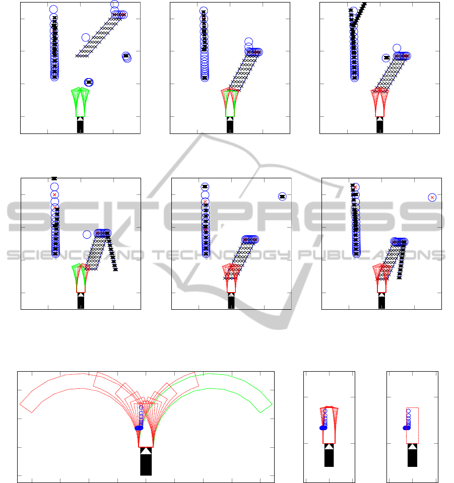
5.2 Analysis of the Test Runs
The system triggers the emergency braking in all
test cases early enough and avoids collisions success-
fully. One exemplary setting with a dynamic object is
shown in Figure 15. In Figure 15(a) an approaching
and correctly predicted object is shown. At t = 14.07s
in Figure 15(b) some trajectories are occupied for the
first time. In Figure 15(c) all trajectories are occu-
pied, but because of new drivable trajectories in Fig-
ure 15(d) less than 0.05 s after the non drivable event
emergency braking is not triggered until t = 14.29s
v
ego
v
ego
v
ob
=
"
v
x,ob
v
y,ob
#
Collision at
t = 15.0 s
Test Run with
Static Object
Test Run with
Dynamic Object
Figure 14: Generation of artificial objects in real sensor
data.
DevelopmentofanEmergencyBrakingSystemforTeleoperatedVehiclesBasedonLidarSensorData
573

Table 1: Moments of triggering for a static object.
Time Before Collision Stopping
Potential Collision Velocity v
c
Distance
a
y,max
= |8
m
/s
2
| 0.33s 6.90
m
/s -
a
y,max
= |2
m
/s
2
| 0.64s - 0.43 m
Trajectory known 0.79s - 1.96 m
in Figure 15(f). Here the system initiates emergency
braking due to completely occupied trajectories for 5
time steps since t = 14.25 s in Figure 15(e).
It is important to mention that the limitation in
acceleration for the operator allows a faster reaction
than in conventional braking systems. Assuming a
static object in the left front of the ego-vehicle, the
triggering of a braking maneuver can happen earlier
because of more limited vehicle dynamics. Figure
16 illustrates the different trajectories 0.34 s before
a potential collision between conventional systems,
teleoperation with limited acceleration range and tele-
operation with one known trajectory, as presented in
(Gnatzig et al., 2012).
The setting in Figure 16(a) shows still one driv-
able trajectory in conventional systems and therefore,
no triggering of a braking maneuver occurs. The
method presented with a range of accelerations for
the operator of up to |2
m
/s
2
| can trigger already at
t = 14.35 s, 0.65s before a potential collision. Apply-
ing a trajectory-based shared autonomy control of the
vehicle, the trajectory determined by the operator is
known. In this case the braking system has to check
only this trajectory and can trigger even earlier. All
results for the moments of triggering are summarized
in Table 1.
6 SYSTEM PERFORMANCE
The sensor data processing presented operates fast
and effectively exclusively with sensor raw data. The
main problem is caused by the measurement errors
of the lidar sensor used that are not detected reliably.
The particle filter is able to track and predict moving
measurement points briskly and robustly.
In the situation assessment there are still faulty ac-
tivations because of measurement faults as described
above. But for correct sensor data the intervention
concept based on provided accelerations for the oper-
ator is well suited for teleoperated driving.
The computations in MATLAB code for a time
increment in real time of dt = 0.01 s actually needs
dt
calc
= 0.022 s on a consumer Intel
r
Core
TM
i7-
2620M CPU @ 2.7 GHz PC running Windows 7 Pro-
fessional with 8 GB RAM. But with the possibility of
externalizing code in a C- or Fortran-compiler, pro-
grams can easily run 10 to 20 times faster, which
makes the system presented real-time capable (Ge-
treuer, 2009).
7 CONCLUSION
This paper has presented a method for an emergency
braking system based on a lidar sensor. With sensor
data processing taking place at raw data level, it has
been possible to reduce the number of measurement
points significantly. By grouping points and selecting
two of them from the lateral edge, the object velocity
has mapped very well and in this way moving objects
have been tracked and predicted robustly. The situa-
tion assessment has compared these predictions with
possible trajectories of the ego-vehicle and derived a
decision as to whether braking is required or not.
The analysis of test runs has demonstrated the
functional capability and the short response time of
the system. In speed ranges of city traffic, collisions
can be avoided successfully. The emergency braking
system with calculations at raw data level enables a
fast reaction time. Furthermore, the application of this
system in teleoperated vehicles possesses two main
advantages compared to conventional automatic brak-
ing systems: First, a lateral acceleration of 2
m
/s
2
will
not be exceeded, which offers the possibility to react
earlier. Second, the trajectory the vehicle follows can
be clearly specified, which makes the decision pro-
cess more precise. Simulation examples show the ad-
vantages of the teleoperated system compared to con-
ventional systems, where collisions can be avoided
successfully.
8 FURTHER RESEARCH
Since lidar sensors are influenced by environmental
conditions, the choice of alternatives or sensor fusion
could further improve its robustness. Combined ob-
ject detection could make possible reactions which
depend on more than measurement points. In this way
a more detailed and adapted motion model of detected
objects in the particle filter would be able to predict
ICINCO2014-11thInternationalConferenceonInformaticsinControl,AutomationandRobotics
574
−10 0 10
0
10
20
30
[m]
[m]
(a) t = 13.48 s
−10 0 10
0
10
20
30
[m]
[m]
(b) t = 14.07 s
−10 0 10
0
10
20
30
[m]
[m]
(c) t = 14.13 s
−10 0 10
0
10
20
30
[m]
[m]
(d) t = 14.15 s
−10 0 10
0
10
20
30
[m]
[m]
(e) t = 14.25 s
−10 0 10
0
10
20
30
[m]
[m]
STOP
(f) t = 14.29 s
Figure 15: Triggering of an emergency braking maneuver.
−20
−15
−10
−5
0
5
10
15
20
−5
0
5
10
[m]
[m]
t=14.66 s
(a) Conventional system with a
y,max
= |8
m
/s
2
|
−5
0
5
0
10
[m]
[m]
t=14.66 s
(b) Teleoperation
with a
y,max
= |2
m
/s
2
|
−5
0
5
0
10
[m]
[m]
t=14.66 s
(c) Teleoperation with
one known trajectory
Figure 16: Trajectories 0.34 s before a potential collision in conventional driving compared to teleoperated driving (v
ego
=
9.5
m
/s).
movements better. Thereby a specific braking reac-
tion can be attributed to an object. The already ex-
isting video cameras of a teleoperated vehicle can be
used for that sensor data fusion. But all refinements
of models and an increasing level of detail must be
weighed up against a slower reaction time of the sys-
tem. Even though this system has been evaluated in
simulation, it still needs to be analyzed during field
tests to corroborate its validity.
DevelopmentofanEmergencyBrakingSystemforTeleoperatedVehiclesBasedonLidarSensorData
575

REFERENCES
Almeida, J. and Araujo, R. (2008). Tracking multiple mov-
ing objects in a dynamic environment for autonomous
navigation. 2008 10th IEEE International Workshop
on Advanced Motion Control, pages 21–26.
Biral, F., Da Lio, M., and Bertolazzi, E. (2005). Combin-
ing safety margins and user preferences into a driv-
ing criterion for optimal control-based computation of
reference maneuvers for an ADAS of the next gener-
ation. In 2005 IEEE Intelligent Vehicles Symposium
proceedings, pages 36–41, Las Vegas, Nevada, USA.
Chen, J., Haas, E. C., and Barnes, M. J. (2007). Human
performance issues and user interface design for tele-
operated robots. IEEE Transactions on Systems, Man
and Cybernetics, Part C (Applications and Reviews),
37(6):1231–1245.
Diermeyer, F., Gnatzig, S., Chucholowski, F., Tang, T.,
and Lienkamp, M. (2011). Der Mensch als Sen-
sor - Der Weg zum teleoperierten Fahren. In
AAET 2011 - Automatisierungssysteme, Assistenzsys-
teme und eingebettete Systeme fuer Transportmit-
tel Symposium am 09. und 10.02.2011, pages 119–
135. Inteligente Transport- und Verkehrssysteme und
-dienste Niedersachsen e.V., Braunschweig.
Getreuer, P. (2009). Writing Fast MATLAB Code.
Gnatzig, S., Chucholowski, F., Tang, T., and Lienkamp, M.
(2013). A System Design for Teleoperated Road Vehi-
cles. In ICINCO2013, 10th International Conference
on Informatics in Control, Automation and Robotics,
pages 231–238, Reykjavik.
Gnatzig, S., Schuller, F., and Lienkamp, M. (2012). Human-
machine interaction as key technology for driverless
driving - A trajectory-based shared autonomy control
approach. In 2012 IEEE RO-MAN: The 21st IEEE
International Symposium on Robot and Human Inter-
active Communication, pages 913–918, Paris. IEEE.
Grover, C., Knight, I., Okoro, F., Simmons, I., Couper, G.,
Massie, P., and Smith, B. (2013). Automated emer-
gency brake systems: Technical requirements, costs
and benefits. TRL Limited.
Hackenberg, U. and Heißing, B. (1982). Die fahrdy-
namischen Leistungen des Fahrer-Fahrzeug-Systems
im Straßenverkehr. ATZ, 84:341–345.
Hong, D., Kang, H.-J., and Yoon, P. (2008). Control Con-
cept for Forward Collision Warning and Mitigation.
In Proceedings of the 17th World Congress - The In-
ternational Federation of Automatic Control, pages
8532–8533, Seoul.
Jansson, J., Johansson, J., and Gustafsson, F. (2002). Deci-
sion making for collision avoidance systems. Society
of Automotive Engineers, Inc.
K
¨
ampchen, N. (2007). Feature-Level Fusion of Laser Scan-
ner and Video Data for Advanced Driver Assistance
Systems. Dissertation, Universit
¨
at Ulm.
Kopischke, S. (2000). Entwicklung einer Notbremsfunk-
tion mit Rapid- Prototyping- Methoden. Dissertation,
Technische Universit
¨
at Carolo-Wilhelmina zu Braun-
schweig.
Ristic, B., Arulampalam, S., and Gordon, N. (2004). Be-
yond the Kalman Filter: Particle Filters for Tracking
Applications. Artech House.
Schmidt, C., Oechsle, F., and Branz, W. (2005). Un-
tersuchungen zu letztm
¨
oglichen Ausweichman
¨
overn
f
¨
ur stehende und bewegte Hindernisse. In 3. FAS-
Workshop, Walting.
St
¨
ampfle, M. and Branz, W. (2008). Kollisionsvermeidung
im L
¨
angsverkehr - die Vision vom unfallfreien Fahren
r
¨
uckt n
¨
aher. In 3. Tagung Aktive Sicherheit durch
Fahrerassistenz, M
¨
unchen.
Tang, T., Kurkowski, J., and Lienkamp, M. (2013). Tele-
operated Road Vehicles : A Novel Study on the Effect
of Blur on Speed Perception. International Journal of
Advanced Robotic Systems, 10.
Thrun, S. (2013). Car localization with particle filter. In
Lecture: Artificial Intelligence for Robotics, chapter 3.
Thuy, M. and Puente Leon, F. (2009). Non-linear, shape
independent object tracking based on 2D lidar data.
2009 IEEE Intelligent Vehicles Symposium, pages
532–537.
Ware, J. and Pan, Y.-J. (2011). Realisation of a bilater-
ally teleoperated robotic vehicle platform with pas-
sivity control. IET Control Theory & Applications,
5(8):952–962.
Wegscheider, M. and Prokop, G. (2005). Modellbasierte
Komfortbewertung von Fahrerassistenzsystemen. VDI
Berichte, 1900:17–36.
ICINCO2014-11thInternationalConferenceonInformaticsinControl,AutomationandRobotics
576
