Development of Autonomous Vehicle
Overview of Autonomous Driving Demonstration in ITS World Congress 2013
Naoki Suganuma
1
and Yutaro Hayashi
2
1
Institute of Science and Technology, Kanazawa University, Kakuma-machi, Kanazawa, Ishikawa, Japan
2
Graduate School of Natural Science and Technology, Kanazawa University, Kakuma-machi, Kanazawa, Ishikawa, Japan
Keywords: Autonomous Vehicle, ITS World Congress 2013.
Abstract: Recently, fully automated autonomous vehicles have been developed, and field examinations in public road
have also been conducted, especially in United States. In this paper, preparation of our laboratory toward
field examination of the autonomous vehicle is reported. Additionally, overview of demonstration in the ITS
world Congress 2013 (ITSWC2013) is reported.
1 INTRODUCTION
Recently, there are many researches related to
autonomous vehicle in all over the world
(Montemerlo, 2008), (Broggi, 2006). Especially, in
the United State and EU, some tests on public road
have been conducted and researches related to this
area become very popular.
Unfortunately, in Japan, autonomous vehicle test
in public road have not been permitted, however
some vehicles are demonstrated in some events in
recent years. For example, in Tokyo Motor show
2011, Toyota Motors exhibits autonomous vehicle
named A.V.O.S. (Advanced Vehicle Operation
System). Moreover, in last year, ITS World
Congress, which is one of the biggest conferences in
this field, is conducted at Tokyo Japan, and some
autonomous vehicles were demonstrated.
In this paper, system overview of autonomous
vehicle developed by Kanazawa University is
introduced, and overview of demonstration in the
ITS World Congress 2013 is shown.
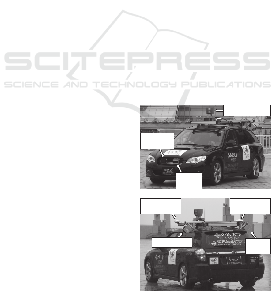
2 ONBOARD EQUIPMENT
Figure 1 shows our autonomous vehicle. In this
vehicle, various sensors and actuators for
autonomous navigation are equipped. Therefore, to
drive such equipment, additional sub-battery is
installed in trunk room, and the sub-battery has a
mechanism to be charged by an alternator, which is
exchanged to large power from original one, via
isolator. Moreover, a 100V 1500W inverter system is
also equipped.
(a) Sensors for obstacle detection
(b) Sensors for localization
Figure1: Onboard perception sensors.
GNSS antenna
(Applanix)
GNSS antenna
(Applanix)
LIDAR(SICK)
LIDAR
(SICK)
LIDAR(Velodyne)
RADAR
(Fujitsuten)
LIDAR
(Ibeo)
545
Suganuma N. and Hayashi Y..
Development of Autonomous Vehicle - Overview of Autonomous Driving Demonstration in ITS World Congress 2013.
DOI: 10.5220/0005101105450549
In Proceedings of the 11th International Conference on Informatics in Control, Automation and Robotics (ICINCO-2014), pages 545-549
ISBN: 978-989-758-040-6
Copyright
c
2014 SCITEPRESS (Science and Technology Publications, Lda.)
In this vehicle, in order to percept under complex
environment like urban road, some sensors are
equipped. In front of the vehicle, a multi-layered
LIDAR (SICK LD-MRS) and millimeter-
wavelength RADAR (Fujitsu-ten) are installed.
These sensors are used to detect distant obstacles.
Moreover, three LIDARs are equipped on roof of the
vehicle. The one of three LIDAR is a high definition
LIDAR (Velodyne HDL64E-S2), and this is used to
detect middle range obstacles. In this LIDAR, 64
laser transmitters are embedded, by rotating 360
degrees around vertical axis, three-dimensional
position of all direction can be given at 10 times per
second. From the LIDAR, since dense three-
dimensional information of 1.3 million point per
second can be given, three-dimensional position of
almost all vehicles, sidewalls, road surface, and so
on can be given up to about 60 meters as shown in
figure 2(a). The rest of two LIDARs(SICK LMS
291-S05) are used to detect the lane markers. They
are positioned in each side of vehicle looking at the
road near the vehicle.
(a) Raw laser point cloud
(b) Example of typical scene percepted by Environment
Perceptor.
Figure 2: Overview of Environment Perceptor.
In addition, to obtain precise vehicle trajectory
for always, GNSS/INS (Applanix POS LV220) is
used. This system consists of Distance Measurement
Unit (DMI), Inertial Measurement Unit (IMU), and
two GNSS receivers, which includes a
GPS/GLONASS azimuth heading measurement
subsystem, and thereby it is possible to obtain
vehicle position at 100Hz by Kalman filtering for
tightly coupled GNSS/INS integration. Therefore, it
is possible to measure vehicle position with accuracy
of 3cm in position, 0.05 degree in attitude when
GPS/GLONASSS signal can be observed, and RTK
correction signal can be given. Additionally, this
system has an accuracy of less than 0.7m after 1km
or 1minute of travel without GPS/GLONASS
signals.
In this vehicle, actuators are installed on steering,
gas pedal, brake, shift and parking brake to realize
autonomous driving. Moreover, to realize natural
driving, horn switch, turn signal and hazard switch
can also be controlled by computer. These actuators
are controlled via motor controller EPOS2
manufactured by MAXSON motor, real-time control
can be achieved via CAN-bus network.
3 SYSTEM OVERVIEW
Figure 3 shows a system overview of our
autonomous vehicle. The software architecture used
in our vehicle is designed as a data driven pipeline,
which individual modules process information
asynchronously. Each module communicates with
other modules via an anonymous publish/subscribe
message passing protocol.
As shown in figure 3, our autonomous vehicle
system is roughly composed of three modules of
Perception, Path planning and Controller modules.
In perception modules, there are three modules of
Lane marker detection, Map matching and
Environment perception. The lane marker module
extracts lane marker on both side of the vehicle by
using side looking LIDARs. From these LIDARs,
distance and reflectivity can be obtained, and lane
marker positions, curvature of the lane marker are
estimated from these measurement. The map
matching module refine pose estimate given from
the GNSS/INS system (Suganuma, 2011), since
typically GNSS/INS system has significant drift
error under urban environment. The rest of
perception module is Environment Perception,
which is main process of these modules and is used
to generate important information to safety driving.
The Environment Perception extracts static obstacles
and estimate motion of dynamic object around the
Ego-vehicle trajectory
Dynamic object and
predicted trajectory
Drivable area (OGM)
Static obstacle (OGM)
Ego-vehicle
Pedestrian
Vehicle
Bicycle
Curb stone
Occlusion
ICINCO2014-11thInternationalConferenceonInformaticsinControl,AutomationandRobotics
546
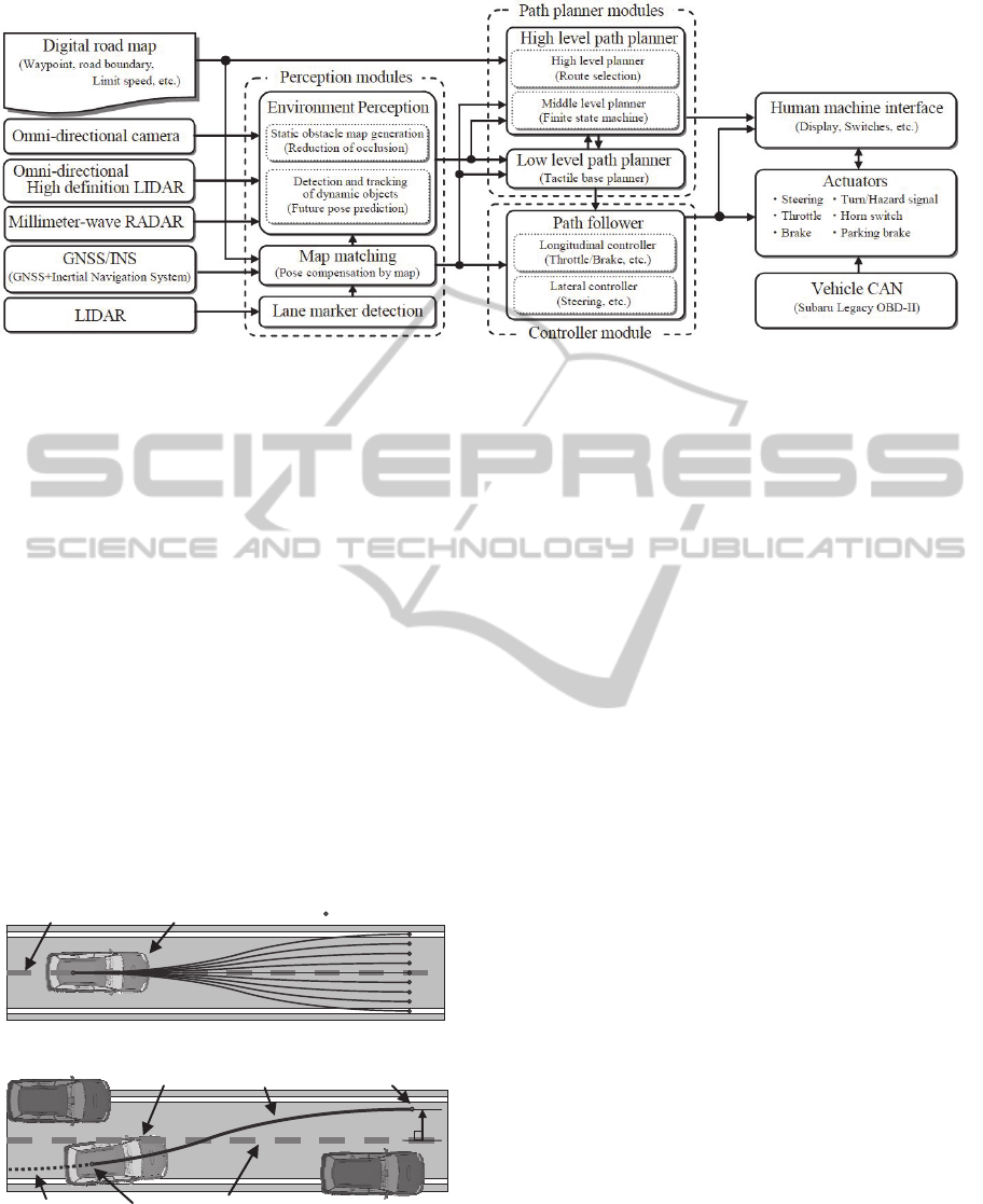
Figure 3: Overview of system architecture of the autonomous vehicle.
vehicle based on onboard sensors. The main sensor
used in this module is a LIDAR mounted on roof of
the vehicle. Figure 2(a) is an example of point cloud
given from this LIDAR. As mentioned above, dense
three-dimensional information of 1.3 million points
per second can be given. However, even such dense
point cloud can be given; there still exist occluded
region as shown in figure 3(a). Therefore, in our
system, Occupancy Grid Maps (OGM) (Elfes,
1989), which is a method to estimate posterior
probability of existence of obstacle, is adopted.
Since the OGM is a method to extract static
obstacle, we can also extract measurement given
from dynamic obstacle by extracting inconsistency
of OGM. Then extracted measurement belongs to
dynamic obstacle is clustered, and the clustered
objects are tracked using Interacting Multiple
Models (IMM) Filter to estimate its motion (Bar-
Shalom). Figure 2(b) is an example of typical scene
perceived by Environment Perception.
Globalpath
PreviewpointsE
g
o‐vehicle
(a) Overview of trajectory candidate generation
Globalpath
Obstacle
p
F
p
0
Obstacle
h
F
Oldtrajectory
Newtrajectory
Ego‐vehicle
(b) Connection between new and old trajectory
Figure 4: Overview of local path planning.
The Path planning modules generate feasible
trajectory which the vehicle can be safely navigated
based on information comes from Perception
modules. In Path planning modules, there are two
main modules. The High Level Path Planner module
consists of High Level planer and Middle Level
Planner. The High Level Planner selects optimal
path from digital map like car navigation system.
Middle Level Planner decides driving action like
forward driving, lane change, stop, and so on
depending on the situation based on Finite State
Machine. The Low Level Path Planner module
generates trajectory, which the autonomous vehicle
finally follow. In our implementation, as shown in
figure 4(a), multiple path candidates are generated
simultaneously, the best trajectory is chosen based
on multiple evaluation value such as safety, lateral
offset from global path, and so on. Each trajectory of
these candidates is generated to become minimum
lateral jerk and to be smoothly connected to old
trajectory as shown in figure 4(b).
The Controller modules play an important role to
follow trajectory generated by Path Planning
modules. In these modules, steering, gas pedal,
brake commands are computed. Additionally, horn,
turn signal, hazard, parking brake and gear shifting
command are also generated. Then these commands
are directly sent to the actuator via CAN.
4 DEMONSTRATION IN THE ITS
WORLD CONGRESS 2013
4.1 Implemented Functions
For the realization of intelligent autonomous driving,
it is necessary to implement many functions to path
planner modules. Following are basic functions
implemented before ITS World Congress 2013.
DevelopmentofAutonomousVehicle-OverviewofAutonomousDrivingDemonstrationinITSWorldCongress2013
547
Automatic Route Selection
A function to select optimal route like car navigation
system was implemented in High Level Path Planner
module. The main difference from car navigation
systems is to consider multiple lanes, and optimal
lane is selected in case of multiple lane roads.
Velocity Keeping
In case of no preceding vehicle conditions, a
function to keep pre-set velocity was implemented in
Low Level Path Planner Module. However, user pre-
set velocity is overwritten in case of some situations,
and more slow velocity is adopted to keep safety.
First situation to overwrite the pre-set velocity is a
case where user pre-set velocity is larger than limit
speed described in digital map. It is clear that we
must to keep limit speed by law. The second
situation is the case where curvature or curvature
rate of the course is significantly large. If the vehicle
was drove at high speed, large lateral acceleration
will be occurred to passenger in case of large
curvature road, and steering wheel will be rotated at
high speed in case of large curvature rate road. To
avoid such dangerous situations, pre-set velocity is
changed to smaller one in such situations. By these
considerations, slowdown before curve is achieved.
Distance Keeping
In case where a preceding vehicle exists, a function
to keep its inter-vehicle distance was implemented in
Low Level Path Planner module. In case where
preceding vehicle exist on far position, autonomous
vehicle is decelerated, and diminish its inter-vehicle
distance until the distance reaches optimal value.
Stop at Designated Position
In case when the autonomous vehicle reaches
destination, stop line and so on, a function to stop at
designated position was implemented in Low Level
Path Planner module.
Obstacle Avoidance
In case where obstacles exist within own lane, a
function to avoid the obstacles is implemented in
Low Level Path Planner module. However, there are
many situations on obstacle avoidance. Therefore
minimum jerk trajectory is selected within drivable
trajectory depending on its situation to become
comfortable driving.
Overtaking
In case where obviously slow preceding vehicle
exists and there is a passing lane, a function to
overtake slow preceding vehicle was implemented.
This overtaking action is implemented on a Finite
State Machine on Middle Level Path Planner,
achieved by changing optimal lane, suggested by
high level path planner, to passing lane.
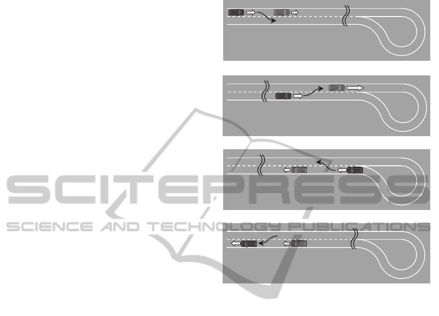
(a) Step 1 and 2
(b) Step 3 and 4
(c) Step 5 and 6
(d) Step 6 and 7
Figure 5: Overview of demonstration in the ITS World
Congress 2013 (ITSWC2013).
These basic functions were adequately tested on
a test course, and it was confirmed that it works
reliably up to about 40km/h.
4.2 Demonstration in the ITS World
Congress 2014
The autonomous driving demonstration in ITS
World Congress 2013 was held in Tokyo. As shown
in Figure 5, the demonstration site is a double lane
course, and round trip autonomous driving was
conducted in the course.
The scenario of the demonstration was as
follows:
Step 1. At first, preceding vehicle was driven at
about 20km/h manually and decelerated to about
10km/h.
Step 2. The autonomous vehicle keeps inter-
vehicle distance while preceding vehicle was
constant velocity of 20km/h. After detection of
preceding vehicle deceleration, the autonomous
vehicle automatically changes its lane and
Goa
6. Return to original lane
5.Deceleration
6.Overtaking
Preceding vehicle
Preceding vehicle
3. Reacceleration
4.Cancellation of
Start
Preceding vehicle
1. Deceleration
2.Overtaking
ICINCO2014-11thInternationalConferenceonInformaticsinControl,AutomationandRobotics
548

(a) Re-acceleration of preceding vehicle while overtaking
(b) Overtaking
Figure 6: Results of demonstration in the ITS world congress 2013.
conducts an overtaking action.
Step 3. Preceding vehicle was re-accelerated up
to about 40km/h manually and overtaking action
of autonomous vehicle was blocked.
Step 4. After reacceleration of preceding vehicle,
autonomous vehicle cancel overtaking action and
return to original lane.
Step 5. After U-turn of the farthest position of
demonstration course, preceding vehicle was
decelerated to about 10km/h manually.
Step 6. The autonomous overtake preceding
vehicle and drive in front of the manually
decelerated vehicle.
Step 7. The autonomous vehicle stops
automatically at manually set destination.
Figure 6 shows some portions of above
demonstration scenario. Through the demonstration,
about 250 passengers including not only specialists
from universities, companies and government, but
also some medias and journalists experienced our
autonomous demonstration. Some comments were
received from participants but there were no
negative opinions, and there were almost good
impressions.
5 CONCLUSIONS
In this paper, system overview of autonomous
vehicle developed by Kanazawa University is
introduced, and overview of demonstration in the
ITS World Congress 2013 is shown. In the future,
we will extend our path planner modules to be able
to use in more complicated situations, and improve
robustness to be able to use in bad weather
conditions for the realization of public road test in
Japan.
ACKNOWLEDGEMENTS
This work was partially supported by Grant-in-Aid
for Scientific Research 24560288.
REFERENCES
M. Montemerlo, et al. 2008. Junior: The Stanford Entry in
the Urban Challenge, In Journal of Field Robotics,
Vol.25, No.9, pp.569-597.
A. Broggi, C.Caraffi, P.P.Prota, P.Zani 2006, The Single
Frame Stereo Vision System for Reliable Obstacle
Detection used during the 2005 DARPA Grand
Challenge on TerraMax, In Proceedings of the 2006
IEEE Intelligent Transportation Systems Conference,
pp.745-752.
N. Suganuma, Uozumi, 2011, Precise Position Estimation
of Autonomous Vehicle Based on Map-Matching, In
Proceedings of the 2011 IEEE Intelligent Vehicles
Symposium.
A. Elfes 1989. Occupancy grids: a probabilistic
framework for robot perception and navigation, In
PhD thesis, Carnegie-Mellon University.
Cox, L. J., and Hingorani, S. L. 1996, An efficient
implementation of Reid's multiple hypotheses tracking
algorithm and its evaluation for the purposes of visual
tracking. In IEEE Transactions on Pattern Analysis
and Machine Intelligence, vol.18, no.2 pp.138-150.
Y. Bar-Shalom, W. D. Blair, Multitarget-Multisensor
Tracking: Applications and Advances, Artech House
Publishers.
DevelopmentofAutonomousVehicle-OverviewofAutonomousDrivingDemonstrationinITSWorldCongress2013
549
