
Design of Safe Reactional Controller for Chamber Pressure in
Climbing Robot CREA
Atabak Nejadfard, Steffen Schütz, Daniel Schmidt and Karsten Berns
Robotics Research Lab , University of Kaiserslautern, Kaiserslautern, Germany
Keywords: CREA, Climbing Robots, Nonlinear Control, Chamber Pressure Control, Sealing, Reservoir Pressure,
Suction System.
Abstract: CREA robot is designed to climb up concrete walls. The robot uses the suction mechanism to provide
adhesion and wheel mechanism for locomotion. Eleven chambers which are connected to one common
reservoir are responsible to produce adhesion force. A controller is developed to independently control each
chamber while satisfying certain criteria on the safety of the robot. It is also designed to reach minimum
friction between active inflatable seals and wall. In conclusion, the controller is able to successfully meet
the conditions of stability, minimum friction and safety.
1 INTRODUCTION
Climbing robots are one of the robotic fields that
despite the long period of research and practical
attempts, engineering and industrial solutions are
still scarce. This paper is reporting an early research
on a promising climbing robot CREA. The robot is
constructed by the cooperation of three major
industrial partners and our robotics lab in University
of Kaiserslautern. It is developed for inspection of
large-concrete walls on dams, motor-way bridges,
cooling towers and etc. The development of this
robot is based on incremental research over almost
10 years and it is an adventurous attempt to improve
the performance of its successful predecessor
CROMSCI.
The Climbing robots, depending on their
application, use various locomotion and adhesive
mechanisms. For climbing a wall with even surface
wheel-driven locomotion is predominant due to its
high speed and manoeuvrability. This kind of
locomotion requires especial adhesion system that
produces adhesive force without effecting the
continuous motion of the robot. As an adhesive
system, suction methods are widely used for
climbing robots with high payloads and heavy
bodies. Nevertheless it is highly energy consuming
and generates undesirable noise. Other methods like
vortex and electro-adhesion have not yet been
maturely developed for real practical applications. A
complete survey on climbing robots is available in
(Schmidt and Berns, 2013). CREA uses wheel-
driven locomotion and highly sophisticated suction
system with eleven chambers with active inflatable
seals.
Passive suction systems generate adhesive force
by sucking the air in to the suction cup and reducing
the inside pressure. We call this mechanism perfect
sealing since the suction cup is completely sealed
and airflow path with ambient air is completely
closed.
In order to be able to move, the perfect sealing
should be avoided. This means that while the seal
itself limits the airflow gap it should not completely
close the flow path. By decreasing the leakage area
the flow speed rises and therefore due to Bernoulli
principle the pressure inside the chamber falls down.
This principle is the basis for adhesion system of
robots like Alicia
3
(Longo and Muscato, 2006), city
climber (Morris and Xiao, 2008), CROMSCI
(Schmidt, 2013) and also CREA. The challenges in
this form of suction system is first to develop a seal
that can control the chamber’s air leakage and
second to produce the large amount of airflow. Seals
are normally in contact with the ground and it is
desirable to have the least possible contact to reduce
inhibitory seal friction. Both city climber and Alicia
3
use bristle seals to reduce the friction but at the
expense of high airflow. However, when the size of
the robot increases, generating such a big airflow is
not beneficial. CROMSCI with a weight of 60 kg
has a one seal for all seven chambers, it is designed
82
Nezhadfard A., Schütz S., Schmidt D. and Berns K..
Design of Safe Reactional Controller for Chamber Pressure in Climbing Robot CREA.
DOI: 10.5220/0005047900820089
In Proceedings of the 11th International Conference on Informatics in Control, Automation and Robotics (ICINCO-2014), pages 82-89
ISBN: 978-989-758-040-6
Copyright
c
2014 SCITEPRESS (Science and Technology Publications, Lda.)
to significantly reduce the air leakage area to gain
under-pressure with much less power but at the cost
of increasing friction. In conclusion reaching a
desirable under-pressure or a reasonable sealing is in
contrast with seal friction and has to be carefully
studied.
CREA uses active seals for each eleven chambers
to have a better control over the air gap between
wall and the chamber to make better trade-off
between friction and under-pressure. In (Kopietz,
Schmidt, Schütz and Berns, 2014) an early work has
been published on how to control these two
contradictory phenomena in CREA. Here we will
comprehensively analyse the suction system of
CREA and develop a stable nonlinear controller to
generate adhesive force with minimum possible seal
friction. This novel method is straight forward with
stability proof and also has simple architecture with
less number of parameters than the method proposed
by the previous work.
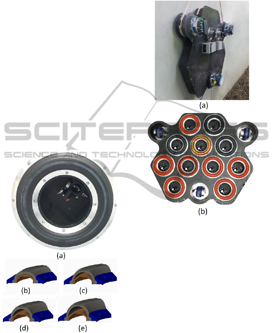
Figure 1: (a) The suction chamber of CREA which
consists of black seal and chamber valve placed inside the
chamber. (b) - (d) shows the CAD model of seal and how
it inflates.
Figure 2: a) CREA robot on the wall. b) Bottom view of
the robot where chambers have different types of seals.
2 SUCTION SYSTEM OF CREA
CREA has eleven chambers which generate under-
pressure to exert adhesive normal force. Each
chamber is connected by control valve to the
reservoir. This valve controls the airflow area
between reservoir and chamber. Typical value of
pressure in the reservoir is -150 mbar and in the
chambers is -10 to -100 mbar with respect to
ambient air pressure. Throughout the paper the
absolute value of the chamber or reservoir pressure
is called under-pressure since it is always below the
ambient air pressure. Three suction pumps are
responsible for generating airflow and keeping the
reservoir pressure around its nominal value. The
most important part of the suction system are the
seals. High pressure air (3bar) is used to inflate the
seals controlled by switching valves (figure 2). Seals
are responsible to adjust the air leakage between
DesignofSafeReactionalControllerforChamberPressureinClimbingRobotCREA
83
chambers and ambient atmosphere. Depending on
the surface and the chamber pressure these seals
have contact with the wall and hence introduce
inhibitory friction which reduces the mobility of the
robot. If the seals continue to inflate after their
contact with wall, they start to push the robot away
from wall which can cause the wheels to lose their
contact and consequently the robot will be unable to
move.
In CROMSCI one all-embracing seal is used for
the seven chambers. If a chamber moves over a hole
or a step (obstacle) it will lose under-pressure but
CROMSCI is unable to adjust the seal inflation since
other chambers are also coupled to this seal and any
change in inflation can cause all others to lose
pressure too. In CREA since each chamber has its
own seal this problem never arises and the robot has
more ability to adapt itself and move over various
obstacles where chambers can independently adjust
their under-pressure and seal inflation.
The electric energy of suction pumps together
with high pressure supply for seal inflation is
provided by a safety cord. In climbing mode, robot
produces under-pressure in its chambers to provide
enough negative normal force to attach the wheels to
the wall. If the negative normal force is enough, the
wheels will have enough friction to push the robot
up. It is desirable to generate as big as possible
adhesive force or accordingly high under-pressure in
the chambers.
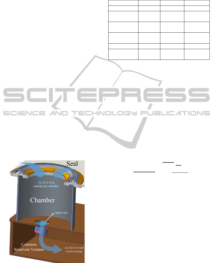
Figure 3: Airflow directions are depicted in CAD model of
the suction chamber.
Table 1: Thermodynamic coefficients in equation (1).
Description notation value dimension
Air density
1.1883 /
Adiabatic
exponent
1.402
Ambient
pressure
10
(1 bar)
pa
Ideal gas
constant
287.058
/
Temperature
293.15 °
Chamber
Volume
0.191
3 CONTROLLER DESIGN FOR
SUCTION SYSTEM
Mathematical model of the chamber system is
introduced to develop a safe and stable strategy for
control of under-pressure inside the chamber.
3.1 Pneumatic Model
In this section we develop a controller for
maintaining the desired chamber pressure. The
thermodynamic model of the chamber system shown
in figure 3 is derived in (Wettach, Hillenbrand,
Berns, 2005). The nonlinear state space model is
written below.
2
1
(1)
In equation (1) the first line depicts the
coefficients which are assumed to be constant. Table
1 shows the value and description of each
coefficient. All the variables are scalar where
is
pressure of the chamber and the only state of the
system,
is its time derivative.
and
are
reservoir and ambient pressures, respectively. The
inputs to this system are
and
which are the
leakage area and valve area of the chamber. The
valve area
is controlled by chamber valve shown
in figure 3 and it adjusts the airflow from chamber to
reservoir. That is why in equation (1) its weight is
the difference between chamber and reservoir
pressure. The same conclusion is valid for chamber
and ambient pressure where seal inflation adjusts the
air leakage area
and also airflow between
outside and chamber. The nonlinear system in
equation (1) has redundancy in control since it has
two inputs and one output.
ICINCO2014-11thInternationalConferenceonInformaticsinControl,AutomationandRobotics
84
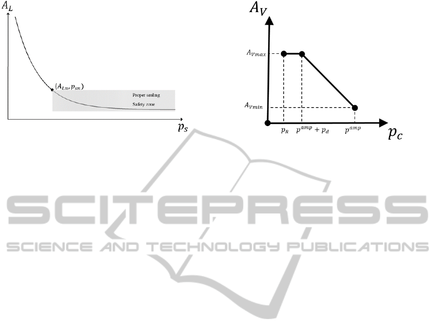
Figure 4: observation based function
.The
subscript is omitted for simplicity.
The main challenge arises in the process of seal
adjustment. The pressure inside the seal is
. By
increasing
the seal starts to inflate which
normally results in reduction of the air leakage.
However the mapping between
and
is
completely dependent on the surface of the wall,
distance of the seal from wall and the normal force
exerted to the seal by the wall. These factors show
that the static function
is strongly
coupled with the environment and it is very difficult
to precisely model. But according to the observation
of the seal behaviour it is obvious that the function
. is strictly decreasing and has the profile as
shown in figure 4. The main feature of this profile is
the knee point
,
where the slope of the
curve decreases when
and this region of
the profile is a convenient working point for the
controller. One main reason is that when
the
acts like a large gain (refer to figure 6)
which pushes the closed loop poles of the controller
toward the imaginary axis and therefore decreases
the stability range of the system, moreover
introduces hard nonlinearity to the system. To solve
this problem first we have to design the seal in a way
that by change in
near the knee point, the
transition from high slope toward smaller one
happens gently (smooth nonlinearity). Second, the
controller has to keep the
while reaching
a stable chamber pressure. In practice we obviously
experienced the unstable oscillatory response of the
controller when the seal shape is not selected well.
Since the focus of this article is on the controller part
we do not discuss more on the design of the seal.
3.2 Control Strategy
The objective is to control the chamber pressure
by using the inputs
and
. Apart from the
unknown function
in the system other
Figure 5: The profile of
in controller.
limitations also have to be considered. Each
chamber has its own controller to individually set
the chamber pressure to the desired value
commanded by the higher planner. However, these
controllers are not completely independent and the
loose coupling between them also introduces
constraints in the control design. The reservoir is
common source of under-pressure for all the eleven
chambers. If one of the chambers loses its under-
pressure the pressure inside of the chamber becomes
the same as ambient pressure and the reservoir also
loses its under-pressure and consequently all other
chambers will be effected. In other words, the
airflow between chamber and reservoir should be
bounded and if it gets more than particular value, the
suction pumps no longer will maintain the desired
low pressure inside the reservoir. The propagation of
high pressure in system is fatal and can result in
collapse of robot. Using valve area
the controller
can adjust airflow of chamber into reservoir. The last
discussion suggests that the controller should not
open the valve until it ensures that the leakage area
is small and airflow will not change dramatically.
The change in
should also be gradual so that
even if an unavoidable change is to occur in
reservoir pressure it would be so slow that other
chambers can track it.
As discussed in the introduction the whole
concept of suction system relies on a trade-off
between friction and chamber pressure. In order to
achieve lower friction the controller should increase
the leakage area
, this will reduce the chamber
under-pressure unless the chamber valve opens
completely to compensate for the large leakage area.
One possible strategy is to use a profile of figure 5
for
. Rise in chamber under-pressure is the sign
of small
and therefore controller can take action
and rise the
a little bit.
The control scenario is as follows: In phase one
DesignofSafeReactionalControllerforChamberPressureinClimbingRobotCREA
85
the controller acts to increase under-pressure from a
small value to desired reference
. The temporal
chamber set point
initially is an arbitrary
predefined ratio of
for example 10%. The
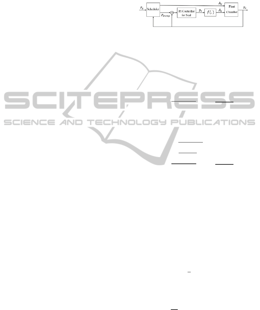
scheduler in figure 6 is responsible to assign the
temporal set points. By putting the set point to this
value the
also takes a small initial value as
computed by the curve depicted in figure 5. Then the
PI controller of seal starts to inflate the sealing to
reach the temporal set point. When the chamber
pressure stabilizes in this set point it means that the
point
,
has reached the safe region in figure 4
and the leakage area is small enough. In the next
step the temporal set point goes up to 20% and
accordingly
rises and the controller starts to
stabilize itself in new set point. This process
continues to gradually push the chamber pressure
toward the final desired value.
In phase 2 it is supposed that the phase 1 is
completed and the controller has reached a stable
point and already made a proper sealing and also
is in maximum value. In this phase the controller
track the changes in
by only adjusting
. The
PI controller simply takes action and the scheduler
puts
and
. The seal
adjusts itself for lower pressures without any change
in
.
In worst case scenario if seal could not reach the
knee point due to big leakage on the floor, chamber
pressure will never rise and the chamber valve will
not be active. This implicit behaviour of the seal
eliminates the need for using any higher level
activation/deactivation module for the chamber.
In other risky situation, if an active chamber with
high under-pressure reaches a hole or obstacle which
suddenly enlarges
so fast that the controller
could not response timely, the chamber will lose
under-pressure and the valve area - enforced by
profile in figure 5- automatically closes and
therefore it will have a very small effect on reservoir
and the other chambers.
Despite the fact that the strategy proves to be
safe but has the disadvantage of slow response and
large steady state time. However when the chamber
under-pressure is stabilized the controller is fast
enough in tracking desired pressure but remains
again slow in response to disturbances.
The chamber pressure control strategy is
strongly distributive and each chamber has
independent reactional response to obstacles and
there is no need for centralized safety check and
chamber activation as was proposed by (Schmidt,
2013) and (Kopietz, Schmidt, Schütz and Berns,
2014). It also adds simple safety parameters such as
and
to be adapted to the surface and
there is no need for complicated safety analysis with
numerous safety parameters.
Figure 6: The block diagram of the feedback system.
3.3 Controller and Stability Analysis
Here we investigate the stability of the discussed
control strategy. Consider the model in equation (1)
for chamber. We rewrite the model here and drop
the sub index since the whole controller analysis is
only for one chamber. The thermodynamic model is
as below:
(2)
In equation (2) the constant coefficients of
equation (1) is replaced with
. We also define new
definitions in following equations to make the model
description simpler.
0
(3)
0
(4)
(5)
Substituting all above definitions in equation (2)
yields:
(6)
is a static function of
and equation (6)
is a simplified version of system dynamics. In order
to achieve a desired chamber pressure
, the
feedback error is defined as:
(7)
(8)
For a first order system the Lyapunov function
is
1
2
(9)
According to Lyapunov stability theorem
(Khalil, 1996) the nonlinear system in (2) is stable if
and only if
0
(10)
It means that error will decrease over time to its
minimal final value, zero. The controller should be
designed in a way that
remains negative.
ICINCO2014-11thInternationalConferenceonInformaticsinControl,AutomationandRobotics
86

(11)
0 ,
0
(12)
The condition to have negative
is that and
has the same sign which yields
or
,
0
(13)
(14)
Where according to new definitions in equations
(3-5), is:
(15)
To control the system, should have the same
sign as. Considering that
and
are positive
and can be correctly measured, can be adjusted
using inputs
and
. However, as it can be seen
in equation (16) these two have contrary effects
on. It is also have to be ensured that the inputs to
the system remain positive.
The whole system is stable in the sense of
Lyapunov, this means that no matter what the
controller inputs are, the chamber pressure is
bounded and always remains between
and
.
However, we attempt to design a controller that is
asymptotically and exponentially stable if the
stability criterion in equation (12) is satisfied.
Now that the stability analysis is provided, It is
possible to prove that the strategy in previous
section is stable. This strategy has two phases. In
first phase, the chamber pressure decreases - under-
pressure increases - with a stepwise procedure to
approach the desired set point
, where it is
smaller than current
, hence in this phase
0. In each step, the scheduler defines a
temporal set point
and
. is negative
and according to equation (14) should be negative
too. Considering equation (15) and the fact that
during each step
is constant, the only
adjustable input to the system is
. As is
shown in figure 6 by increasing
,
decreases
until it tends to zero. A PI controller as in equation
(17) is implemented to adjust
.
.
0,
0
(16)
Since 0, PI controller increases
until
becomes so small that the term
in equation
(15) dominates and 0. Now, the trajectory of the
system is entered the attraction region of the
controller and the stability criterion is valid and
hence the controller will converge exponentially
to
.
Of course, at first, the system state is not in the
attraction region and system is stable in the sense of
Lyapunov but not exponentially. However, we used
the model information of equation (15) together with
observation model of figure 4 to guide the trajectory
toward attraction region. This process is blind since
the controller have no information that if there is
such an attraction region or not. For example if there
is a hole in the wall that the convenient sealing does
not take place, inflation of sealing will not help and
then the controller can decide that there is an
obstacle and it will shut down the chamber.
In phase one, if the robot passes the first step to
increase
then there is a guarantee that the
action of sealing is probable - no obstacle - and
therefore in next steps the controller will be enough
confident to open the
more which is risky in the
presence of obstacles.
In the second phase of the strategy, the robot
already has reached a stable pressure, which yields
0
(17)
Hence, it was assured that the sealing is proper.
The most prominent feature of the second phase is
that the state trajectory is in attraction region and
is kept constant at maximum. The controller start to
track the reference values by only adjusting the seal.
Since the sealing process is finished and the state
trajectory is already inside the attraction region –
equation (12) is balanced - the controller response is
swift and fast.
4 IMPLEMENTATION RESULTS
The controller is implemented on a digital signal
processing (DSP) device with the sampling rate of
100 Hz. All the sensory data from the pressure
sensors of reservoir, chambers and seals are
connected to DSP. Actuators for chamber valve
servomotor and seal pressure switches are also
commanded by the same DSP. In the following
results the leakage area (
) and valve area (
) are
normalized by
. The normalized values
,
are calculated by the following equations.
(18)
(19)
The step response of the control strategy in
phase one is depicted in figure 7. In this experiment
the
̅
is 0.3. The seal starts to inflate until it
DesignofSafeReactionalControllerforChamberPressureinClimbingRobotCREA
87
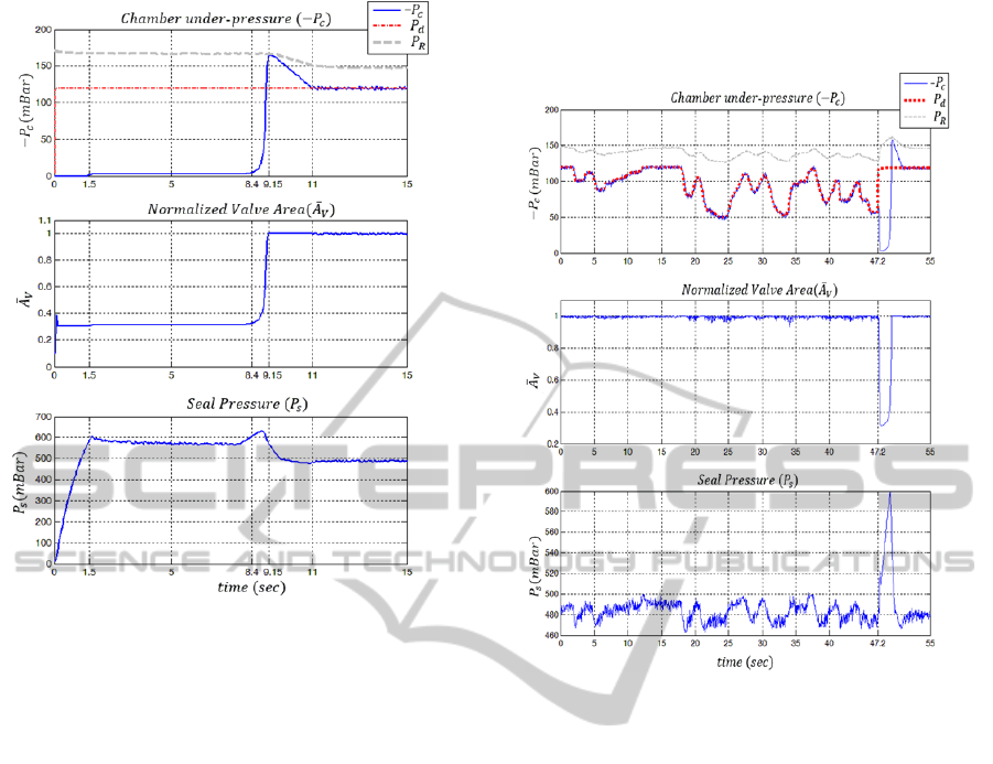
Figure 7: Step Response of the controller in phase 1.
reaches the wall surface at 1.5. Afterwards, the
chamber pressure slowly increases until 8.4.
During this interval the controller conservatively
start to open
until at 8.4 perfect seal
happens and chamber pressure suddenly increases.
takes the same profile as
since they are
linearly dependent as shown in figure 5.
Consequently, the PI controller adjusts
to reach
desired pressure value (
). The main feature of this
response is that the reservoir pressure (
) changes
smoothly and has no fluctuations. The controller is
not designed to have fast response since in the case
of climbing robot, safety is the main design criterion
where the controller managed to achieve such a
satisfactory safe response by suppressing the airflow
inside the chamber. The controller opens valve only
when that it is assured the leakage area is small. One
of the advantages of this method is that no exact
model of the system is used to estimate airflow and
the controller manages to adjust the airflow by only
observing the behavior of the system.
The controller also achieved the smallest steady-
state seal pressure. In order to have small interaction
between seal and wall or minimum friction, the seal
pressure should be as small as possible. As shown in
figure 7, at 1.5 the seal reach the surface
at
600, however eventually it settles
down at 11 at 500, which provides the
lowest possible normal force and friction on the
wall.
Figure 8: The tracking response of the controller in phase
2.
The tracking response of the controller is shown
in figure 8. In this case, the controller works in
phase 2. It is able to follow arbitrary desired signal
with acceptable precession of 3 mBar. As we
discussed, since in this phase the state trajectory is
already in attraction region, the response is swift and
stable. However at time 47.2s a very abrupt
change occurred in desired signal that the controller
were unable to follow and therefore chamber under-
pressure is lost. In this situation adhesive force
decreases which is considered highly risky.
However, as soon as the under-pressure drops, the
controller closes
and preserves the reservoir
pressure.
One of the important assumptions in the design
of the controller is to assume that the curve shown in
figure 4 is valid throughout the experiment. This
curve is a simplified model of the controller
interaction with the environment (wall). The
controller is valid if the function
is
strictly decreasing. In figure 9, the identification data
is depicting the function
. The data gathered
under the condition of stable chamber pressure and
in fact shows the working points of the controller in
ICINCO2014-11thInternationalConferenceonInformaticsinControl,AutomationandRobotics
88
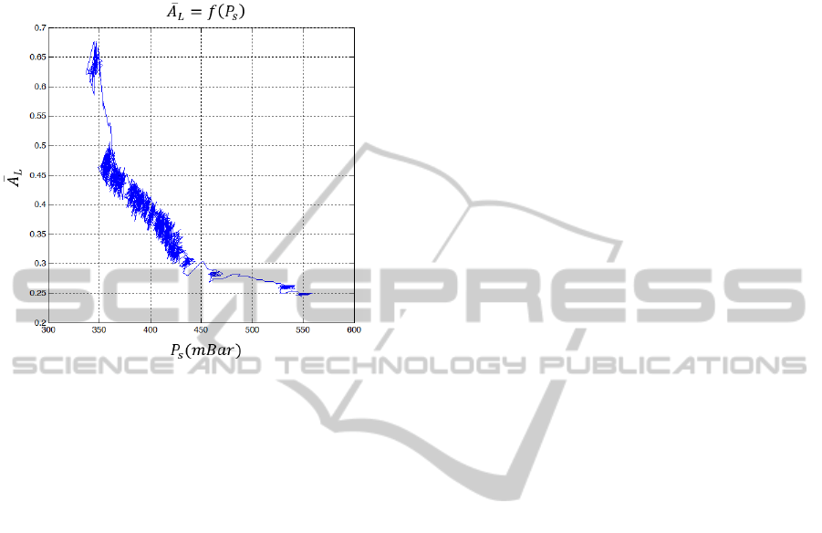
steady-state. As it can be seen in the figure, the
concentration of the points are around knee of the
curve which is a testimony to the analysis given in
section 3.1.
Figure 9: Identification data of the seal behaviour under
the condition of stable chamber pressure.
5 CONCLUSION
This paper reports the design procedure of a
nonlinear controller for the chamber pressure of the
climbing robot CREA. The controller not only
moves toward a stable attraction region but also
satisfy rigorous conditions of safety. In previous
works the safety issue is included in the path
planning high level control which administrates the
overall behaviour of several chambers and decides
according to the predefined safety measures. Many
parameters are defined for safety measures and the
response of the system is slow since the process is
high level. In this paper we incorporated reactional
safety features directly into the stability of the
system. Important feature of the system is that the
equilibrium of the controller is dependent on the
environment (wall surface). The controller observes
and interacts with environment to determine the
equilibrium and then moves towards the attraction
region. If the controller could not find equilibrium, it
will continue to search without putting robot at risk.
Its response is reactional and fast especially in risky
situations to guarantee safety. The controller is very
simple to implement in low level DSP to increase
the sampling rate. It also considerably reduces the
burden on high level planner since the control
strategy is designed in a way that the chambers work
highly distributive.
However, there are some open questions that need to
be investigated. One is the assumption of the
function
. This assumption is valid in
working on common concrete walls but there are
some specific situations like the existence of
relatively big steps on the wall that have different
leakage profile. In this cases high level planner
should be involved in overall decision making
process. We are also working on a better design for
seal to improve the behaviour of the sealing process.
It is also desirable to develop estimation and
learning methods for friction, force and coordination
of different chambers because of the strong coupling
with environment.
REFERENCES
Schmidt, D., Berns, K., 2013. Climbing robots for
maintenance and inspections of vertical structures—A
survey of design aspects and technologies. In Robotics
and Autonomous Systems, volume 61, issue 12, Pages
1288-1305.
Longo, D., Muscato, G., 2006. The Alicia
3
climbing robot:
a three-module robot for automatic wall inspection. In
Robotics & Automation Magazine, volume 13, issue 1,
pages 42-50.
Morris, W., Xiao, J., 2008. City-Climber: Development of
a Novel Wall-climbing Robot, In Journal of Student
research, volume 1.
Wettach, J., Hillenbrand, C., Berns, K., 2005.
Thermodynamical Modelling and Control of an
Adhesion System for a Climbing Robot, In IEEE
International Conference on Robotics and Automation
(ICRA), Barcelona, Spain.
Schmidt, D., 2013. Safe Navigation of a Wall-Climbing
Robot-Risk Assessment and Control Methods. The
doctrol thesis, University of Kaiserslautern, Germany,
(verlag Dr. Hut, Munich Germany 2013).
Kopietz, K., Schmidt, D., Schütz, S., Berns, K., 2014.
Friction Optimization Adhesion Control of a Wheel-
Driven Wall-Climbing Robot. In Proceedings of
International Conference of Climbing and Walking
Robots (CLAWAR).
Khalil, H., 1996. Nonlinear Systems, The book, Prentice
Hall, Englewood Cliffs, NJ, 2
nd
edition.
DesignofSafeReactionalControllerforChamberPressureinClimbingRobotCREA
89
