
A Variable Structure Controller for a Class of Hyper-redundant
Arms
Decebal Popescu
1
, Nirvana Popescu
1
, Mircea Ivanescu
2
and Dorin Popescu
2
1
Department of Computing Science, POLITEHNICA University of Bucharest, Splaiul Independentei, Bucharest, Romania
2
Department of Mechatronics, University of Craiova, A.I. Cuza, Craiova, Romania
Keywords: Hyper-redundant Robot, Continuum Arms, Control.
Abstract: The paper treats the control problem of a class of hyper-redundant robot constituted by a chain of continuum
segments. The technological model basis is a central, long and thin, highly flexible and elastic backbone.
The driving system is a decoupled one. The main parameters of the arm control are determined by the
curvature and curvature gradient. The dynamic model is inferred. A sliding mode control system is used in
order to achieve a desired shape of the arm. The stability of the closed loop control system is proven.
Numerical simulations are also provided to verify the effectiveness of the presented approach.
1 INTRODUCTION
The goal of this paper is to implement a control
system for a class of hyper-redundant robots with
continuum components. The tentacle robots
represent one of the most attractive domains of
robotics during the last decades. The control of these
systems is very complex and several researchers
have tried to offer solutions as it will be further
discussed. In (Chirikjian, 1990), (Robinson, 1999),
(Gravagne, 2000), (Gravagne and Walker, 2000),
(Jones and Walker, 2006) the kinematic models
were analysed, based on a “backbone curve” that
captures the robot’s macroscopic geometric features.
In (Mochiyama, 1999), (Hirose
and Umetani, 1976)
the problem of controlling the shape of a robot with
two-degree-of-freedom joints was also investigated
using spatial curves. A controller for continuum
robots was developed by using neural network feed-
forward components in (Braganza, 2007),. Other
researchers derived a new kinematic model by using
the differential geometry (Walker, 1999), (Kapadia,
Walker and Dawson, 2009), (Hannan, 2005) or
introduced a real-time controller for continuum
robots (Jones, 2006). In (Kapadia, 2009) it was
proposed a sliding controller for extensible robots.
Other papers (La Spina, 2007), (KeJun, 2009),
(Webster and Jones, 2010) have developed several
biomimetic prototypes with undulatory action.
Our paper treats the control problem of a class of
light weight hyper-redundant robots. The
technological model basis is a central, long and thin ,
highly flexible and elastic backbone. The driving
system is a decoupled one. The main parameters of
the arm control are determined by the curvature and
curvature gradient. The dynamic model is inferred.
A sliding mode control system is used in order to
achieve a desired shape of the arm.
The paper is structured as follows: section 2
presents technological structure, section 3 analyses
the dynamic model, section 4 treats the control
algorithm, section 5 verifies the control laws by
computer simulation and section 6 contains the
conclusions.
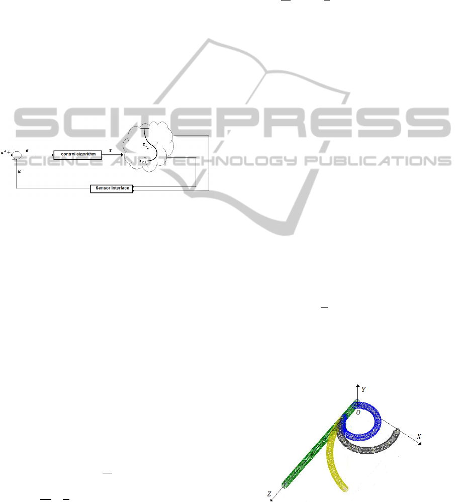
2 TECHNOLOGICAL ARM
The technological model basis is an arm with a
distributed mass. The 3D model basis from Fig 1
consists of a central, long and thin, highly flexible
and elastic backbone. It is made from homogeneous
materials, the bending represents the main motion
and we neglect the deformations of axial
tension/compression and shear. The arm is divided
in several segments, each segment having its own
driving system. The motion of the arm, the
bending, is determined by antagonistic cables
(tendons) attached to the terminal point of each
segment and a DC motor driving system. These
cables develop the driven torques τ
i
, i=1, 2…
121
Popescu D., Popescu N., Ivanescu M. and Popescu D..
A Variable Structure Controller for a Class of Hyper-redundant Arms.
DOI: 10.5220/0005005901210126
In Proceedings of the 11th International Conference on Informatics in Control, Automation and Robotics (ICINCO-2014), pages 121-126
ISBN: 978-989-758-039-0
Copyright
c
2014 SCITEPRESS (Science and Technology Publications, Lda.)

The cables ensure an independent bending for each
segment so that the segment driving control is a
decoupled one.
Figure 1: The technological arm.
3 DYNAMIC MODEL
We consider a hyper-redundant arm constituted by a
serial connection of a number of continuum arm
segments, with equal lengths L (Fig 2). For the
segment i, the curvature is defined by
0i
0
=
dω
i
s=0
ds
=
dθ
i
s=0
ds
dq
i
s=0
ds
κ
1i
=
dω
i
s=l
ds
=
dθ
i
s=L
ds
dq
i
s=L
ds
(1)
and we assume that the continuity of the arm
curvature requires the following segment boundary
conditions
Figure 2: The backbone model.
κ
0 i
0
= κ
1 i-1
(L)
(2)
with
κ
0 0
0
= 0
(3)
Using the same procedure as in (Gravagne,
2000), we obtain the partial differential equations
(PDE) of the arm segment,
I
ρ
ω
i
= EI ω
ss
i
- B ω
i
+h
i
(ω
i
)
(4)
where ω
i
=ω
i
t,s
, ω
i
=(θ
i
,q
i
)
T
, s∈Ω,ω
i
=
∂ω
i
∂t
⁄
, ω
s
= ∂ω
i
∂s
⁄
, I
ρ
is the rotational inertial
density matrix, I
ρ
=diag I
ρ
θ
, I
ρ
q
, I
ρ
θ
=I
ρ
q
=I
ρ
, B is
the equivalent damping matrix of the arm,
B=diag
b
θ
,b
q
, b
θ
= b
q
=b and represents the
nonlinear component vector determined by
gravitational components , h
i
= (h
1
i
,h
i
2
)
T
. The initial
and boundary conditions are
ω
i
0,s
=ω
i
0
(s)
(5)
EI ω
s
i
t,l
= τ
i
t
, ω
s
i
t,0
=0
(6)
ω
s
0
t,0
=0
(7)
ω
0
t,0
=0
(8)
where τ
i
is the equivalent moment generated by
the forces F
i
at the end of the arm segment i,
τ
i
t
= F
i
.r ,r is the radix of the moment,
τ
i
=
τ
θi
τ
qi
, F
i
=
F
θi
F
qi
(9)
The dynamic model of the arm can be expressed
in terms of the curvature κ
1 i
t,L
as
I
ρ
L
2
A κ
(t) = -b
L
2
Aκ(t) -
EI
L
Cκ(t)+
1
L
τ(t)+h(κ)
(10)
κ
0
=
κ
0
(11)
where
κ = (κ
11
, κ
12
, ... κ
1n
)
T
(12)
with
κ
i
t
=
κ
1 i
(t, L)
(13)
represents the new state vector, κ∈ R
n
, τ denotes
the general input of the arm,
τ= (τ
1
,τ
2
,…..,τ
n
)
T
(14)
the linear components are defined by the (n x n )
matrices
A =
1 0 0 0 . . . .0
2 1 0 0 . . . 0
2 2 1 0 . . 0
……………
2 2 2 2 2 1
, C=
0 0 0 . . . 0
1 0 0 . . 0
0 1 0 . .0
. . . . . . .
0 0 0 . .1 0
(15)
and the nonlinear component is determined by
ICINCO2014-11thInternationalConferenceonInformaticsinControl,AutomationandRobotics
122
h=(h
,h
,….,h
)
T
(16)
where h
= h
i
(κ
i
) and satisfices the inequality
(Popesu,2014)
‖
h
ω
‖
≤M
‖
κ
‖
(17)
4 CONTROL ALGORITHM
We consider a desired state κ
d
,κ
d
∈ R
n
, that satisfies
(10) with initial condition (11) and we define by
e
t
=κ
d
-κ(t)
(18)
the error variable, e ∈R
n
.
The control problem consists of finding the
control law τ(t), on the boundary s=L of each
segment such that the error converges to zero.
Figure 3: The control system.
The main idea of the control system is based on
the variable structure control associated with the
special properties of the physical system. We
propose a controller with a boundary torque variable
structure control. Let us define by S (t) the sliding
surface, associated with the model (10) and the error
(18)
S
t
=e
t
+σ e(t)
(19)
where
S=
S
1
, S
2
… S
n
T
, σ=diag (σ
1
, σ
2
… σ
n
), σ
i
are
positive constants.
Theorem 1. For the system described by (10)
with the initial conditions (11), if the variable
structure controller is given by
∆τ= -K
1
sgn
S
-K
2
Ce sgnS
T
K
2
Ce
-K
3
AI
ρ
σ
-1
-bIesgnS
T
AI
ρ
σ
-1
-bIe
(20)
K
1
>0
(21)
K
2
C-MI-
EI
L
C>0
(22)
K
3
L
-
L
2
II
ρ
Aσ
-1
- b I > 0
(23)
where K
j
=diagk
j1
, k
j2
,..,k
jn
,j=1,2,3 represent
the control coefficients, then the motion of the
system will reach the sliding line S=0 and then keep
it there , where ∆τ is defined by
τ = τ
d
- ∆τ
(24)
and τ
d
represents the torque vector on the desired
position κ
d
that satisfies the equations,
-
EI
L
C
d
+
1
L
τ
d
+hκ
d
=0
(25)
Proof. See Appendix
5 NUMERICAL SIMULATIONS
Consider a dynamic model of a vertical hyper-
redundant arm, with two arm segments, with the
length of the segment L=1 m, the rotational inertial
density I
ρ
= 0.001 kg m
2
, the bending stiffness
EI=0.1Nm
3
, the viscous coefficient
b
θ
=0.06 Nms/rad. These constants are scaled to
realistic ratios for a long thin arm. The initial and
boundary conditions are: θ
0
s
= 0 , θ
s
t, 0
=0,
EIθ
s
(t,L) =τ, where is the torque applied at the top
of the arm segment. We consider that the uncertain
term h
θ
is defined by the gravitational
components. For the characteristic values of the arm
parameters,
0.8
⁄
, 10
⁄
,
4.10
, associated with this thin long arm, the
inequality (17) is satisfied for M = 10. The arm is
simulated by a chain of vertebrae.
We simulated two motions. The first motion is a
XOZ plan motion, the arm (the both segments) is
moving toward the desired position defined in term
of curvature, κ
θd
=-
π
14
. A control law (20) with the
controller gains, k
1θ
i
= 20, k
2θ
i
= 8, k
3θ
i
= 3 is used,
where k
1θ
i
, k
2θ
i
, k
3θ
i
, i=1, 2…., verifies the conditions
(21) - (23). The motion of the arm, several
intermediary positions and final positions are
illustrated in Figure 4.
Figure 4: A XOZ plan motion.
AVariableStructureControllerforaClassofHyper-redundantArms
123
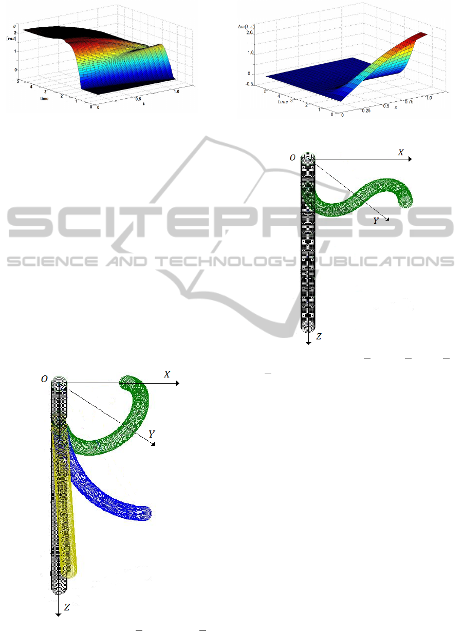
Figure 5: The state evolution for the plan motion.
The time evolution can be analysed if we use the
distributed parameter dynamic model described by
PDE (4) with boundary conditions defined by the
control law of torque (20).The state variable
evolution is presented in Fig 5.
A 3D motion of a 2-segment arm is presented in
Figure 6.The desired position is defined by
1θd
= κ
2θd
= -π/14, κ
1qd
= κ
2qd
= -π/24. The control
parameters were selected as
k
1θ
i
=k
1q
i
= 20 ,k
2θ
i
=k
2q
i
=8,k
3θ
i
=k
3q
i
=3, i=1,2…
The both segments bend with the same curvature.
The error evolution is presented in Figure 7. In
Figure 8 is presented a new motion of this arm, with
a different desired position of each arm
segment:
κ
1θd
=-π/14,κ
1qd
=-π/24, κ
2θd
=π/14,κ
2qd
=-π/24
The good performances of the proposed control
algorithm are concluded from the graphics.
Figure 6: A 3D motion:
1θd
= κ
2θd
= -
π
14
, κ
1qd
= κ
2qd
= -
π
64
.
Figure 7: The error evolution for the 3D motion.
Figure 8: A 3D motion
1θd
= -
π
14
, κ
1qd
= -
π
64
, κ
2θd
=
π
14
,
κ
2qd
= -
π
64
.
6 CONCLUSIONS
The paper presents the control problem of a class of
hyper-redundant robot constituted by a chain of
continuum segments. The technological model basis
is a central, long and thin, highly flexible and elastic
backbone. The driving system is a decoupled one.
The main parameters of the arm control are
determined by the curvature and curvature gradient.
The dynamic model is inferred in terms of the
curvature. A sliding mode control system is used in
order to achieve a desired shape of the arm. The
stability of the closed loop control system is proven.
Numerical simulations are also provided to verify
the effectiveness of the presented approach.
ICINCO2014-11thInternationalConferenceonInformaticsinControl,AutomationandRobotics
124

ACKNOWLEDGEMENTS
This work has been supported by PPCA 150/2012
grant of the Romanian Executive Agency for Higher
Education, Research, Development and Innovation
Funding (UEFISCDI).
REFERENCES
Robinson ,G. , Davies, G. B. C., 1999 “Continuum Robots
– a State of the Art”, Proc. IEEE Int. Conf. on
Robotics and Automation, Detroit, May 1999, Pp.
2849 – 2854.
Gravagne, Ian A., Walker, Ian D., 2000, on the Kinematics
of Remotely - Actuated Continuum Robots, Proc.
2000 IEEE Int. Conf. on Robotics and Automation,
San Francisco, April 2000, Pp. 2544-2550.
Gravagne, Ian A., Walker, 2000 Ian D., Kinematic
Transformations for Remotely-Actuated Planar
Continuum Robots, Proc. 2000 IEEE Int. Conf. on
Rob. and Aut., San Francisco, April 2000, Pp. 19-26.
Chirikjian, G. S., Burdick, J. W.,1990, an Obstacle
Avoidance Algorithm for Hyper-Redundant
Manipulators, Proc. IEEE Int. Conf. on Robotics and
Automation, Cincinnati, Ohio, May 1990, Pp. 625 –
631.
Mochiyama , H., Kobayashi, H.1999, the Shape Jacobian
of a Manipulator with Hyper Degrees of Freedom,
Proc. 1999 IEEE Int. Conf. on Robotics and
Automation, Detroit, May 1999, Pp. 2837- 2842.
Braganza, D., D.M. Dawson, Walker, N. Nath, N., 2007,
“A Neural Network Controller for Continuum
Robots”, IEEE Transaction Robotics, Vol. 23, Issue 6,
Dec. 2007, Pp. 1270 – 1277.
Walker, I., M. Hannan, M., 1999, “A Novel Elephant’s
Trunk Robot”, AIM ’99, Pp. 410 – 415.
Jones, B., I. D. Walker, 2006, “Practical Kinematics for
Real-Time Implementation of Continuum Robots”,
IEEE Trans. Robotics, Vol. 22, No. 6, Dec. 2006, Pp.
1087 – 1099.
Kapadia, I. Walker, D. Dawson,2009 “a Model – based
Sliding Mode Controller for Extensible Continuum
Robots”, Recent Advances in Signal Processing,
Robotics and Automation, ISPRA Conf., 2009, Pp.
103 – 120.
Popescu, N., Popescu, D., Ivanescu, M., Nitulescu, M.,
2014, the Curvature Control of a Hyper-Redundant
Robot Proc. of Int. Symp of Robotics, Munich, June,
2014 ,Pp 251-257.
G. La Spina, M. Sfakiotakis, D. Tsakiris, a. Memciassi, P.
Dario, 2007, Polychaete-like Undulatory Robotic
Locomotion in Unstructured Substrates, IEEE Trans
on Robotics, Vol 23,No 6,Febr 2007, Pp1200-1212.
Kejun Ning, F.Worgotter, 2009, a Novel Concept for
Building a Hyper-Redundant Chain Robot, IEEE
Trans on Robotics, Vol 25,No 6,Dec 2009, Pp 1237-
1248.
Rucker, D. C., B. A. Jones, R. J. Webster III,2010, a
Geometrically Exact Model for Externally Loaded
Concentric-Tube Continuum Robots, IEEE Trans on
Robotics, Vol 26,No 5,Oct 2010, Pp769-780.
Bailly, Y., Y. Amirat, G. Fried, Modeling and Control of a
Continuum Style Microrobot for Endovascular
Surgery, IEEE Trans on Robotics, Vol 27,No 5,Oct
201, Pp 1024-1030.
Bajo, A., N. Simaan, 2012, Kinematics-based Detection
and Localization of Contacts along Multisegment
Continuum Robots, IEEE Trans on Robotics, Vol
28,No 2,April 2012, Pp 291-302.
B. A. Jones, I. D. Walker, „Kinematics for Multisection
Continuum Robots”, IEEE Transactions on Robotics,
VOL. 22, NO. 1, Febr. 2006, 43- 51.
R. Fareh, M. Saad, M. Saad, „Workspace Tracking
Trajectory for 7-DOF ANAT Robot using a
Hierarchical Control Strategy”, 2012 20
th
mediterranean Conference on Control & Automation
(MED), Barcelona, Spain, July 3-6,2012 122-128.
H. Shang, J. F. Forbes, and M. Guay. “Feedback Control
of Hyperbolic Distributed Parameter Systems”,
Chemical Engineering Science, 60:969 – 980, 2005.
F. Fahimi, H. Ashrafiuon, and C. Nataraj, (2002) “an
Improved Inverse Kinematic and Velocity Solution for
Spatial Hyper-Redundant Robots,” IEEE Trans. on
Robotics and Automation, Vol. 18, No. 1, Feb. 2002,
Pp. 103–107.
S. Hirose, Umetani,Y,(1976), Kinematic Control of
Active Cord Mechanism with Tactile Sensors, Proc of
2nd Int CISM-IFT Symp. on Theory and Practice of
Robots and Manipulators, Pp 241-252,1976.
A. Kapadia, I. Walker, D. Dawson, (2009), “a Model –
based Sliding Mode Controller for Extensible
Continuum Robots”, Recent Advances in Signal
Processing, Robotics and Automation, ISPRA Conf.,
2009, Pp. 103 – 120.
R. J. Webster, B. A. Jones, “Design and Kinematic
Modelling of Constant Curvature Continuum Robots:a
Review”, the International Journal of Robotics
Research, 29 (13), 2010, Pp. 1661-1683,
M. W. Hannan, “Real-Time Estimation for Continuum
Robots using Vision”, Robotica, Vol 23 /Issue 05,
Sept. 2005, Pp 645-661.
APPENDIX
From (10) - (11), the error dynamics will be
described by
I
ρ
L
2
A e
(t) = -b
L
2
Ae(t) -
EI
L
Ce(t)+
1
L
Δτ(t)
+ Δh(κ
d
)
(A.1)
e(0) = e
0
(A.2)
∆h = h - h
κ
d
(A.3)
Let us consider the Liapunov function
AVariableStructureControllerforaClassofHyper-redundantArms
125

V
t
=
1
4
l S
T
t
I
ρ
Aσ
-1
S(t)
(A.4)
The time derivative of is given by
V
=
l
2
S
T
I
ρ
Aσ
-1
S
(A.5)
where in order to simplify the notation, the
variable t is omitted.
V
=
l
2
S
T
I
ρ
Aσ
-1
(e + σe
)
(A.6)
By evaluating (A.6) along with the solutions of
(A.1), it turns out that
V
=
L
2
S
T
I
ρ
Aσ
-1
-Abe-
EI
L
S
T
Ce+S
T
Δh
+
1
L
S
T
Δτ
(A.7)
Now, substituting the control ∆τ from (20), after
simple additional manipulations, we obtain
V
≤ -
1
L
K
1
‖
S
‖
-S
T
K
2
C-MI-
EI
L
C
‖
e
-S
T
(
K
3
L
-
L
2
I)(I
ρ
Aσ
-1
-b I)
‖
e
‖
(A.8)
Using the conditions (21) - (23), this inequality
can be rewritten as
1
‖‖
(A.8)
ICINCO2014-11thInternationalConferenceonInformaticsinControl,AutomationandRobotics
126
