
A Component-based User Interface Approach for Smart TV
Jes´us Vallecillos, Javier Criado, Nicol´as Padilla and Luis Iribarne
Applied Computing Group, University of Almeria, Almeria, Spain
Keywords:
Component-based Architecture, SmartTV, Services.
Abstract:
The fast growth and diversity of technological devices currently being produced is benefiting areas such as
“ambient intelligence”. This area attempts to integrate information technology in any personal environment.
However, to construct service/application software that adapts to different environments, there must be tech-
niques available that favor this type of development. Component-based software Engineering (CBSE) is a
discipline of the software engineering that integrates (previously constructed) components to build new soft-
ware systems. This paper presents a CBSE approach to build Graphical User Interfaces (GUI) at run-time.
Both a component-based perspective of the user interface and a set of component relationships are presented
in the paper. As a case study, this paper also describes an application built for an emerging computation envi-
ronment, Smart TV. A running example is also presented through the paper putting some Web-based solutions
to build User Interfaces together (e.g., Wookie, W3C Widgets, Node.js).
1 INTRODUCTION
We are currently witnessing very fast growth of de-
vices in a diversity of technologies (e.g., smart-device
integration at home, such as SmartTV, smartphones,
tablets, etc.). One area benefited by the appearance
of these new devices is “Ambient Intelligence” (Re-
magnino et al., 2005). This area attempts to integrate
information technology in any personal environment,
facilitating daily activities as transparently as possi-
ble with respect to the information systems. How-
ever, before such integration can be possible, the ser-
vice/application software must be adapted to the dif-
ferent environments. Therefore, it is very important
to have systems that facilitate human-computer inter-
action in many environments and enable their design
to be adapted to this diversity of devices.
Component-based Software Engineering, CBSE
(Crnkovic and Larsson, 2001) is a software engineer-
ing discipline that can assist in facilitating this in-
teraction and enable the adaptation of many devices
during software development. CBSE improves soft-
ware development by reusing it, contributing relia-
bility, and reducing the time required for creating
such software. Contrary to traditional software de-
velopment, CBSE is focused on integrating previ-
ously constructed software components in the con-
struction of the system following a bottom-up devel-
opment perspective instead of a traditional top-down
one. This concept of reuse and management of com-
ponents is also present in standards such as IEC/PAS
62814 (Belli, 2013).
As application domain, the research work on user-
interface development is currently involved on im-
proving new CBSE solutions. For instance, Figure 1
shows an example of one user interface constructed
by assembling components that may be seen in the
Netvibes-type interface
1
. This kind of user interface
(i.e., based on components) gives a wide catalog of
components that can be added or eliminated to cus-
tomize the appearance to the user-interface as well as
the services it provides. However, Netvibes compo-
nents are isolated in the user interface, and therefore,
no exchange information among component, limiting
possibilities they might offer. This leads to the ques-
tion of how to create user interfaces based on interre-
lated components adapted to many environments.
Our research attempts to find an answer to this is-
sue focusing on the development of component-based
architectures. In addition, we try these architectures
to be deployed or executed in different platforms.
Furthermore, it is necessary that the components of
the architectures can be interrelated with each other.
Once these architectures are deployed, they should
not remain static, but they must be able to change
and adapt their component structure at run-time. In
order to accomplish these goals, we have proposed a
methodology for adapting component-based architec-
1
Netvibes web page: http://www.netvibes.com
455
Vallecillos J., Criado J., Padilla N. and Iribarne L..
A Component-based User Interface Approach for Smart TV.
DOI: 10.5220/0004999304550463
In Proceedings of the 9th International Conference on Software Engineering and Applications (ICSOFT-EA-2014), pages 455-463
ISBN: 978-989-758-036-9
Copyright
c
2014 SCITEPRESS (Science and Technology Publications, Lda.)
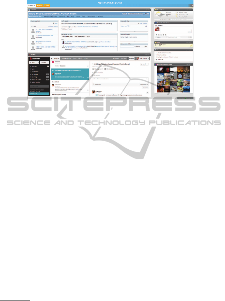
Figure 1: An example of Component-based User Interface.
tures at run-time (Iribarne et al., 2010; Iribarne et al.,
2011). This methodology relies on Model-Driven Ar-
chitecture (MDA) levels to describe the component-
based software and on a client-server model. Then,
components and architectures are defined in two lev-
els of abstraction: Platform IndependentModel (PIM)
level and Platform Specific Model (PSM) level. The
second one will be used to deploy the architecture on
the client side. Therefore, from the PIM level, it could
be possible to realize different PSM architectures de-
pending on the platform, by using a regeneration pro-
cess (Criado et al., 2013). Moreover, this method-
ology also allows the interaction captured from the
client side to modify the architectural definitions. On
the other hand, this interaction could only generate the
communication between components. Anyway, both
processes will be managed in the server side of our
system, as a gateway.
The proposed methodology is not suitable for all
component-based architectures. It is valid for archi-
tectures built from medium/high grained components
which encapsulate some independent behavior, but
they should or must be able to interact with other
components of the architecture. In addition, these ar-
chitectures should be able to change at run-time with
the aim of adapting to the new user’s needs or the
new system’s requirements. One specific domain for
the application of such architectures is the develop-
ment of interactive systems. This article focuses on
a component-based interactive system for one Smart
TV user interface which was tested in a Samsung
Smart TV Emulator
2
. The components used in this
environment, included all the necessary for this pur-
2
https://www.samsungdforum.com/Devtools
pose, such as visual and functional features, are ex-
plained. A set of relationships necessary for the com-
munication and adaptation of the component-based
architecture was also fixed. However, the manage-
ment at the PIM level and the realization of the PSM
architectures are not addressed, which are issues out
of the scope of this paper. Therefore, we can summa-
rize the contributions of this paper as follows:
• Application of our methodology in component-
based user interfaces for Smart TV.
• Description of components and relationships used
in the methodology.
• Implementation of the approach from the point of
view of the client and the server.
• Illustration of our approach through a running ex-
ample.
• Development of a prototype of interactive sys-
tem, implementing the proposed methodology
and available on the web.
The remainder of the paper is organized as fol-
lows. Section 2 describes a sort of component-based
GUI developed for an interactive Smart TV system.
It serves as a running example used through the pa-
per. Section 3 presents some component and relation-
ship issues and it exemplifies them by using the pre-
vious GUI. Section 4 explains the technological so-
lution adopted to implement our architecture in the
Smart TV environment. Section 5 reviews and dis-
cusses some related work. Finally, some conclusions
and future work are presented in Section 6.
ICSOFT-EA2014-9thInternationalConferenceonSoftwareEngineeringandApplications
456
2 COMPONENT-BASED UI ON
SMART TV
The main research of the paper concentrates on de-
veloping component-based software architectures for
interactive systems. Henceforth, we will use CBA to
refer to Component-Based Architectures. Although a
CBA can be applied in several environments, they are
currently used to build interactive systems. The user
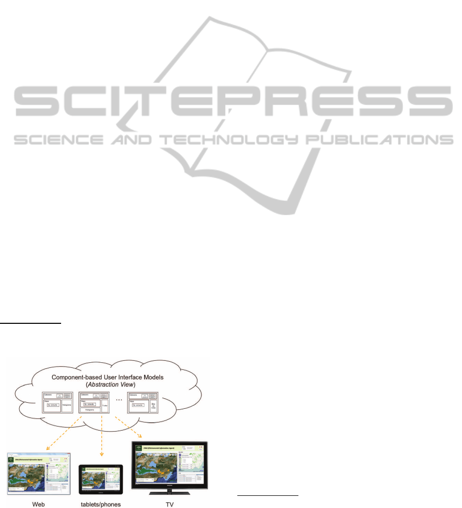
interface in our interactive system (a CBA instance),
as shown in Figure 2, could be visualized on different
platforms supporting different technologies.
Of course, depending on the technology used
in each environment, the interface’s functional and
graphic features may vary in an attempt to adapt to
it. These variations may be necessary for several dif-
ferent reasons; for example, one might be such as the
characteristics of the used device (screen size, net-
work connection bandwidth, etc.). To achieve this
adaptation, the system has components with similar
functionality, but specific to each device. This arti-
cle does not describe how this adaptation to the en-
vironment is done. On the contrary, the goal pursued
is to concentrate on a concrete technology, the Web
technology, in a concrete environment as defined by
Samsung for its Smart TV series. Below, we describe
the application developed for this environment,which
will serve as the basis for describing all the elements
that make up our component-based software architec-
ture and the technology used to put it into service.
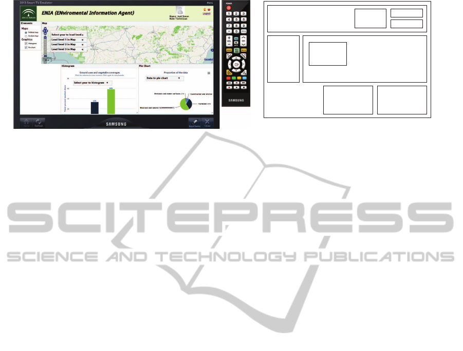
The development of applications for Smart TV
platforms is booming, and especially applications de-
veloped for Samsung Smart TV. Figure 3-(a) shows
a CBA application being developed for the Andalu-
sia Regional Government (Spain). This application
implements an environmental management system
called ENIA
3
based on user profiles. In this appli-
3
ENIA project: http://acg.ual.es/enia
Figure 2: Adaptation of the UI to different platforms.
cation, the users interact for land uses and plant cov-
ers information in the Region of Andalusia. In this
example, the interface is made up of a set of com-
ponents associated with the workspace of a technical
user profile. Since the Samsung Smart TV platform
uses a Web-based technology, the application can eas-
ily be adapted to other environments that use the same
technology. On the other hand, Figure 3-(b) shows an
abstract representation of this interface. This repre-
sentation makes it easier to understand the function-
ing of our component architecture, since it enables it
to be abstracted from the visual features and working
only with its characteristics. Based on this abstract
representation, an abstract model of components can
be created. This abstraction allows us to describe the
component distribution and composition in the inter-
face, leading to a component architecture model.
Let us examine both representations in Figure 3.
A
Header
component is located at the top in both fig-
ures. This component controls the access to the sys-
tem and the language preferences. For this task, the
Header
component consists of three components:
(a) the
User
component, which is used to identify the
user that interacts with the system,
(b) the
Languages
component, responsible for
changing the language of the interface compo-
nents, and finally,
(c) the
Logout
component, which closes the session
of the connected user.
All these components share a common purpose,
managing the user profile. Component
Header
is a
clear example of how CBSE is used to create more
complex components by integrating more basic ones.
Other components, used by the user to perform the
application domain tasks, appear in the interface. The
Map
component shows a map of the study area with
the results of the queries mentioned below. The map
was implemented using OpenLayers
4
. Within this
component is the
Options
component, which con-
tains the queries that can be shown on the map. At
the left of the
Map
component is the
Elements
com-
ponent, which enables the user to select the compo-
nents that can be shown on our interface prototype.
Finally, underneath
Map
component, are two compo-
nents (the
Histogram
and
Pie Chart
components)
used to show information related to the current query.
More information about this running example is avail-
able on the web
5
.
Having described the application developed, let us
see the internal structure of a component and the main
interrelationships that among them.
4
OpenLayers: http://www.openlayers.org/
5
Running example: http://acg.ual.es/enia/cbuismarttv
AComponent-basedUserInterfaceApproachforSmartTV
457
Elements
Header
User
Languages
Logout
Map
Options
Pie Chart
Histogram
(a) CBA in Samsung Smart TV. (b) CBA abstract representation.
Figure 3: An interactive system example for Smart TV.
3 COMPONENTS AND
RELATIONSHIPS
As observed in Figure 3, a user interface in our system
is made up of a set of components. Each component
in this interface is divided internally into two mod-
ules, the User Interaction Module, which manages
interaction with the user (and includes the visual fea-
ture, when the interface is graphical, such as buttons,
checkbox, etc.), and the Functional Module, which
performsthe main tasks of the component (such as ac-
cessing the databases, etc.). Each component also has
a set of internal ports by which it relates to other com-
ponents, enabling message exchange among them and
providing more dynamic, adaptable behavior. Man-
agement of these communications is done by a series
of functions included in each component. Most com-
ponents created in an application usually include both
modules. However, components can be implemented
using only one or none of those modules. Thus three
component subtypes may be distinguished:
(a) Functional Component. A component including
only this module is used basically to implement
the underlying functionality of an application. For
instance, a component for registering a new user
in the system.
(b) User Interaction Component. A component that
includes only this module basically manages user
interaction and shows visual content (when user
interfaces are visual, naturally) related to the do-
main information. For instance, the
Histogram
component used to display some data from the
Map
component.
(c) Container Component. A component that does
not include any of the mentioned modules, is
named as a container. This component subtype is
used to contain other components which develop
a common task or purpose together. For instance,
the header section at the user interface.
All components in a user interface is contained
in one special container component called the
Main
Container
, which represents the architecture of the
user interface, that includes all the components and
their relations. Figure 4 shows the inner architec-
ture of the study application, that is, a user inter-
face made up of eight components:
User
,
Languages
,
Logout
,
Histogram
,
Map
,
Pie Chart
,
Elements
and
Options
components.
Moreover, in the system exists a
Kernel
service
with three main capabilities, in charge of manag-
ing the user interface. The Lifecycle and Relation-
ships Management capability manages the life cycle
of components along their relationships. Transaction
Management controls all of the messaging between
components through their relationships. Finally, the
Display Management capability manages and main-
tains the distribution, design and dimension of the in-
terface components.
Let us go now to analyze the relationships among
the application components. A Kernel’s Transaction
Management capability is used for managing commu-
nications established among components by the type
of relationships existing among them. Each compo-
nent in the application has a sort of ports used for
sending/receiving information to/from another com-
ponent. To be able to understand the functioning of a
port, the concept of a binding relationship must first
be defined. A binding relationship is a connection
between the ports of two components.
There can only be one binding relationship be-
tween two components. These binding relationships
provide many possibilities by adding performance
and restrictions to information exchange.
The relationships used in the application are: (a)
composition (⊐); (b) association (≈); (c) dependency
ICSOFT-EA2014-9thInternationalConferenceonSoftwareEngineeringandApplications
458
(≫); and (d) producer-consumer relationship (⊢).
A composition relationship (i.e., ⊐) shows that a
component is included in another and cannot be ac-
cessed through its ports by any other component out-
side the composition. This relationship occurs when
the components that form part of the composition
have a purpose or target in common, and develop this
purpose together. Re-examining Figure 4, we can
see that there is a composition relationship between
the
Header
component and the
User
,
Logout
and
Languages
components. This relationship exists be-
cause they share a common purpose which is to con-
trol interface access and provide a language appropri-
ate to the interface components, and they develop this
purpose together.
The association relationship (i.e., ≈) between two
components appears when information necessary to
both is exchanged between them. The
Languages
component has an association relationship with the
User
component because the user can change the lan-
guage of all the components, including the
User
com-
ponent. Since a component included in a composi-
tion cannot be accessed by another component nor in
the same composition, the
Header
component has to
perform the
Languages
component task. Therefore,
there are some association relationships that start out
from the
Header
component to the
Histogram
,
Pie
Chart
,
Map
and
Elements
components.
A dependency relationship (i.e., ≫) exists when
a component cannot exist, or its existence makes no
sense without another component. Thus, there is a de-
pendency relationship between the
User
component
and the
Logout
component because it would make no
Figure 4: Components and their relationships.
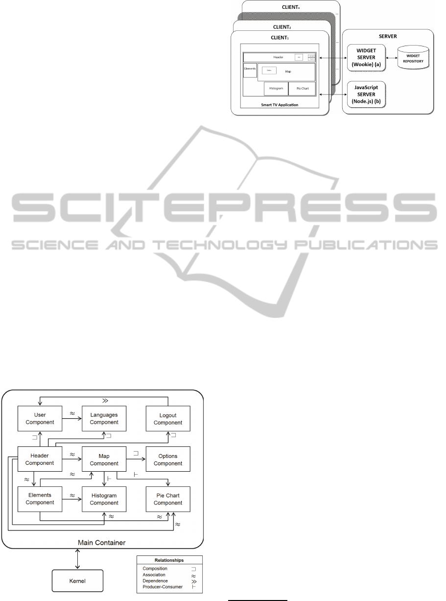
Figure 5: Client-Server Architecture
sense for there to be a
Logout
component in the in-
terface if the
User
component were not there.
Finally, the producer-consumer relationship (i.e.,
⊢) occurs when a component produces information
which is consumed (that is, used) by another compo-
nent. The
Map
componenthas two producer-consumer
relationships with the
Pie Chart
and
Histogram
components. These relationships are due to the
Map
component, providing information through the se-
lected options and marked areas, useful for compo-
nents that use statistical graphics.
4 IMPLEMENTATION ISSUES
As mentioned in Section 2, there are Smart TV plat-
forms where applications based on Web technolo-
gies are being developedto achieve greater integration
with external devices and services. Our component-
based interactive system model uses a client-server
architecture, as shown in Figure 5. The user interface
for each user of the system is in the client side. Each
interface may be different depending on the user pro-
file and his personal preferences. In the server side of
our architecture, we can found a set of servers based
on Web technologies. This servers are in charge of
managing the component repository and the commu-
nication between components. The employed tech-
nologies are analyzed in more detail below.
4.1 Client Side technology
As mentioned above, the applications in Samsung
Smart TV are based on Web technology. Therefore,
our components were designed following this tech-
nology using the W3C Widget specification
6
. This
specification proposes a structure that is easily adapt-
able to our component model.
Table 1 shows an example of the internal structure
of the
Map
component. There are two main files in the
6
W3C Widget: http://www.w3.org/TR/widgets/
AComponent-basedUserInterfaceApproachforSmartTV
459

structure,
index.html
and
config.xml
. These files
start up the resources necessary to execute the compo-
nent. In addition to these two files, the specification
proposes a folder structure that contains the function-
ality of the components and what they look like. In
the content folder,there are two subfolders. One is the
interaction
folder, where elements comprising the
component interface and the management of events
generated by these elements reside. In the example,
this functionality is found in the
UIscript.js
file.
Apart from this, the
functional
folder also includes
the rest of the component functionality. In our exam-
ple, the file
Taskscript.js
includes the underlying
functionality for map management.
A piece of the
Taskscript.js
file is shown in
Table 2. It shows the function necessary to receive a
map layer (
receiveLoadLayer
) and the function for
deleting a map layer (
receiveDeleteLayer
). These
functions make up the main functionality of the
Map
component. These two functions are analyzed in de-
tail. It may be seen that the
Map
component commu-
nicates with another component,
Options
, through
ports by means of the
websocket.on()
function. The
first parameter of the function (
receiveLoadLayer
)
shows the port of the
Map
component, by which the
external information is received. The second parame-
ter is a function which sends the request to the destina-
tion component, represented by the
componentName
label. This function represents the behavior to be ex-
ecuted when the port of this component is invoked.
This function also has a parameter to describe the
name of the layer (
nameLayer
), and a parameter to
locate the data to be acquired (
dataLayer
). After this
process, the received information must be checked
and validated from that expected by the component
(if clause). This condition is satisfied because, when
the components are loaded in the interface, they are
given a unique name which identifies them through-
out their life cycle. Once checked, the next func-
tion (
newLayer
) performs the information process-
ing (i.e., load a new layer on the map). The function
receiveDeleteLayer
also follows the same process.
Once the set of components to be executed in our
Table 1: Structure of the Map Component in W3C Widget.
Map.wgt
index.html //Main File
config.xml //Config of resources
content/
interaction/
UIscript.js //Visual functionality
images/
header.png
functional/
Taskscript.js //Data base functionality
Table 2: Example of Taskscript.js.
01: <script>
02: // connection to server
03: var websocket = io.connect(‘http://acg.ual.es:6969’);
04:
05: // connection to server with the component username
06: websocket.on(’connect’, function(){
07: // call to server through function ’adduser’ and
08: // send necessary parameters
09: websocket.emit(’adduser’, getUrlVars()[‘ID_user’]);
10: });
11: websocket.on(
12: ’receiveLoadLayer’,
13: function(componentName, nameLayer, dataLayer){
14: if(componentName == ’Options’){
15: newLayer(nameLayer, dataLayer); }}
16: );
17: websocket.on(
18: ’receiveDeleteLayer’,
19: function(componentName, nameLayer){
20: if(componentName == ’Options’){
21: deleteLayer(nameLayer); }}
22: );
23: </script>
system has been constructed, they are integrated in a
user interface. To do this, each user interface is con-
structed using a Web page where the components (to
be executed at a given moment for a given user) are
identified. Table 3 shows a fragment of the Web page
index.html
of the application described in this ar-
ticle. This page is loaded in the Samsung Smart TV
when a user accesses the system. The web page shows
all those components included under a
<body>
label,
and by means of a
<div>
label. Label
<body>
repre-
sents the
Main Container
of a user interface. Label
<div>
includes as parameters: the
id
and the
class
of the component, being the latter the type of widget.
This
<div>
-based structure provides a feature in the
user interface because of the frame that is displayed
around the visible components. It also enables the
user to perceive the interface as a set of components
that can be manipulated according to his preferences.
Label
<iframe>
, which contains the concrete com-
ponent identified by its
id
and linked by
src
, is also
included under a
<div>
label. To delete a component
from the interface, label
<div>
must be deleted.
4.2 Server Side technology
As mentioned, we have developed a system com-
prised of several servers based on Web technologies.
In Figure 5 may be observed that a server called
Apache Wookie
7
has been deployed. This server is
used to manage our component repository, making it
possible to deploy, update and store components con-
structed following the W3C Widget specification.
In addition to a component managing server, we
7
Apache Wookie: http://wookie.apache.org/
ICSOFT-EA2014-9thInternationalConferenceonSoftwareEngineeringandApplications
460

Table 3: Embedding Wookie & widgets into the main page.
01: <html>
02: ...
03: <body>
04: <!-- Component Header -->
05: <div id=’Header’ class=’widget’>
06: <iframe id=’header’
07: src=’http://acg.ual.es/wookie/deploy/acg.ual.es/
08: wookie/widgets/Title/index.html?idkey=
09: 5.pl.pu6bbHaBxkWRMWLyfd2m.sl.VMLw.eq.&
10: proxy=http://acg.ual.es:80/wookie/proxy&st=’>
11: </iframe>
12: </div>
13: <!-- Component Elements -->
14: <div id=’elements’ class=’widget’>
15: <div class=’title’> <h4>Elements</h4> </div>
16: <iframe id=’ielements’
17: src=’http://acg.ual.es/wookie/deploy/acg.ual.es/
18: wookie/widgets/Elements/index.html?idkey=
19: .pl.z5.sl.ArbxzPbvESCH43BKZcw1fxI.eq.&proxy
20: =http://acg.ual.es:80/wookie/proxy&st=’>
21: </iframe>
22: </div>
23: <!-- Component Political Map -->
24: <div id=’politicalMap’ class=’widget’>
25: <div class=’title’> <h4>Map</h4> </div>
26: <iframe id=’ipoliticalmap’
27: src=’http://acg.ual.es/wookie/deploy/acg.ual.es/
28: wookie/widgets/MapOptions/index.html?idkey=
29: gvXeT11dUC8JI40U9UetR.pl.gzhJ8.eq.&proxy=
30: http://acg.ual.es:80/wookie/proxy&st=’>
31: </iframe>
32: </div>
33: ...
34: </body>
35: </html>
used other server based on JavaScript called Node.js
8
to manage data in/out. This server is directed at events
by making use of a non-blocking input/output model,
which enables easy distributed construction of appli-
cations. The use of this server provides the capac-
ity for making changes in the interface, such as load-
ing, removing, resizing or redistributing a component
within the interface itself (without reloading it).
To manage information sharing between compo-
nents, we employed a communication by message ex-
change. In this communication method, the exchange
of the message is done by means of “Node.js”, which
acts as an intermediary receiving the message of a
component and sending it to the destination compo-
nent. This communication behavior is part of the re-
lationships mentioned above. Example of this kind of
communication appears in the code shown in Table 2.
As may be observed in line #3, the
Map
component is
connected to the server providing to the
Map
with the
information necessary to load or delete a given layer.
To carry out this type of communication, our system
uses a “Node.js” server plug-in called
socket.io
9
.
This plug-in assists in developing communications at
run-time for applications located on different plat-
forms.Finally, to insert a new component in a user in-
8
http://nodejs.org/
9
http://socket.io/
terface this behavior is perfomed in the main page file
of the user interface shown in Table 3. Assume we
wish to insert the
Histogram
component and select it
from the
Elements
component.
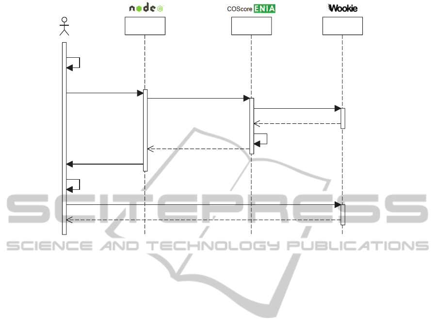
Figure 6 shows the sequence diagram describing
the steps taken by the system to load the
Histogram
component. First, to initiate this process, the user
should select the
Histogram
checkbox included in
the
Elements
component (we can see this check-
box in Figure 3). Next, component
Elements
emits a message to
Node.js
server by means of the
socket.emit function (message #2 in Figure 6). This
function requires three parameters: the identifier of
the port on which the message is issued (addWidget
in this case), the owner of the graphical user interface
(named as user), and the identifier of the component
that must be inserted (Histogram in this case). Then,
the
Node.js
server invokes the addWidget function of
the Kernel system based upon previous information
(#2.1). Sequentially, the
Kernel
calls the createWid-
getInstance function of Wookie server (#2.1.1). Now,
Wookie
creates a widget instance of the Histogram
(componentID) component for the user stated and re-
turns the corresponding widget instance data for iden-
tification and usage purposes (#2.1.1 and #2.1.2).
Once this information is obtained, the
Kernel
builds the corresponding HTML code to be inserted
into the user interface (#2.1.3). This code is returned
to
Node.js
server (#2.1.4) and is emitted to the client
application, that is, to the user interface (#2.2). Into
the
MainContainer
component, there is a function
in charge of listening the addWidget web socket port
and that inserts the new code in the SmartTV appli-
cation (#3). Finally, since the new HTML code ref-
erences the widget instance residing in Wookie, the
client performs a GET method call to the Wookie
server in order to obtain the new widget instance
(#4 and #4.1). The behavior of the running exam-
ple can best tested in a SmartTV emulator available at
http://acg.ual.es/enia/cbuismarttv.
5 RELATED WORK
In some studies such as (Teixeira-Faria and Rodeiro,
2011) the authors define a type of components called
Abstract Interaction Object (AIO) which can describe
an interface as a set of abstract components. In (Sa-
vidis, 2005) the author also describes a user interface
as a set of AIO call Virtual Interaction Object (VIO),
which gives an object definition that helps to devel-
oper to develop an object for different platforms. (Bo-
dart and Vanderdonckt, 1996) describes other compo-
nents, such as the Concrete Interaction Object (CIO),
AComponent-basedUserInterfaceApproachforSmartTV
461
:RRNLH.HUQHO1RGHMV
&OLHQW6PDUW79$SSOLFDWLRQ
JHWQHZFRPSRQHQWUHVSRQVH
ZLGJHWLQVWDQFHGDWD
JHWQHZFRPSRQHQWUHTXHVW
FUHDWH:LGJHW,QVWDQFHXVHUFRPSRQHQW,'
QHZFRPSRQHQW+70/FRGH
EXLOGQHZFRPSRQHQW+70/FRGH
DGG:LGJHWXVHUFRPSRQHQW,'
LRVRFNHWLQXVHUHPLWDGG:LGJHWFRPSRQHQW&RGH
VRFNHWHPLWDGG:LGJHWXVHUFRPSRQHQW,'
DGGQHZFRPSRQHQWFRGHWR*8,
FOLFNFKHFNER[
FRPSRQHQW,'
Figure 6: Operation sequence.
which are defined as visual user interface compo-
nents, and are used to display and manipulate infor-
mation in database systems. However, none of these
works use a CBA perspective for SmartTV.
In previous studies in (Iribarne et al., 2010) and
(Iribarne et al., 2011), a CBA of widget-type compo-
nents is proposed. These components are applied to
a Web-based Information System, WIS, because of
their flexibility, adaptability, accessibility and man-
ageability by different people or groups of people
with interests in common and different profiles lo-
cated in different places. This kind of interface
provides the possibility of reorganizing the interface
components according to the user needs, improving
the user experience in performing his tasks. Further-
more, in previous work, it was initiated the develop-
ment of component-based systems to be deployed on
the TV platform (Fernandez and Iribarne, 2010; Val-
lecillos et al., 2012). The present paper is based on
both studies but improvesthe component and relation-
ship definitions, and also provides a real implementa-
tion of Smart TV interactive system.
Finally, the development of software technologies
for smart TVs is an evolving field, where component-
based interface proposals have not yet been devel-
oped. Some of them propose the development of
specific applications for television and others us-
ing standard television broadcasts add advanced ser-
vices to the broadcast. One example of the first
trend is the Multimedia Home Platform, MHP (Mar-
tin et al., 2010) for application development, which
defines a common platform (middleware) for interac-
tive smart TV applications, regardless of interactive
service provider or type of television where it is ex-
ecuted. Some examples of the use of this platform
are (Blanco-Fern´andez et al., 2008) and (Pazos-Arias
et al., 2006). Another platform based on the second
proposal is Hybrid Broadcast Broadband TV, HbbTV
(Kuzmanovic et al., 2012), which uses standard wide-
band television broadcasts to show user entertainment
services, such as games, social networks or interactive
advertising using Web technology.
6 CONCLUSIONS AND FUTURE
WORK
Nowadays there is fast growth of devices on different
technological supports that enable the public access to
IT services/applications in any personal environment.
However, to construct these products, techniques for
their development must be available.
Component-based Software Engineering (CBSE)
is a software engineering discipline that facilitates
this labor by focusing on the integration of previously
constructed software components for systems. Our
research concentrates on the development of software
based on a CBSE perspectivefor a number of environ-
ments, such as the application described in this article
for the Samsung Smart TV environment.
In addition, we have described a sort of compo-
ICSOFT-EA2014-9thInternationalConferenceonSoftwareEngineeringandApplications
462

nent based GUI developed for an interactive Smart
TV system. Furthermore, this system serves as a
running example used through the paper. We pre-
sented some component and relationship issues and
we exemplified them by using the previous GUI.
We explained the technological solution adopted to
implement our architecture in the Smart TV en-
vironment. In order to better understand the in-
teractive Smart TV system, we created a web
page (http://acg.ual.es/enia/cbuismarttv/) where some
other information about this work is available, includ-
ing the emulator installation process, the Samsung
Smart TV project developed, and a video where the
interaction with the application is showed.
As future work, we will carry on a study of the
users and user profiles registered in the system, which
could be useful to trace user interaction. With this
information we will be able to create interactive sys-
tems adapted to the user’s needs. In order to im-
prove the justification of the proposed method, we in-
tend to conduct a controlled experiment with differ-
ent groups and different kinds of users. Each user or
group could perform some development part and then
fill in a survey form, for example, by comparing our
approach with traditional methods to develop GUIs or
component-based GUIs. On the other hand, we want
to extend our system with some new functionalities
to provide a support for cooperative tasks. Finally, we
intend to deploy our system in other platforms such as
tactile devices, or use other interaction methods such
as Natural User Interfaces (NUI).
ACKNOWLEDGEMENTS
This work was funded by the Spanish Ministry
of Economy and Competitiveness (MINECO) under
Project TIN2013-41576-R and the Andalusian Re-
gional Government under Project P10-TIC-6114 and
the Spanish Ministry of Education, Culture and Sport
(MECD) under a FPU grant (AP2010-3259). This
work was also funded by the CEiA3 and CEIMAR
consortiums, and the Applied Computing Group.
REFERENCES
Belli, F. (2013). Dependability and software reuse – Cou-
pling them by an industrial standard. In: IEEE 7th
International Conference on Software Security and
Reliability-Companion (SERE-C), pp. 145–154.
Blanco-Fern´andez, et al. (2008). An MHP framework
to provide intelligent personalized recommendations
about digital tv contents. Software: Practice and Ex-
perience, 38(9):925–960.
Bodart, F. and Vanderdonckt, J. (1996). Widget standard-
isation through abstract interaction objects. Intitut
d’Informatique, Facultes Universitaires Notre-Dame
de la Paix, Namur, Belgium.
Criado, J., Iribarne, L., and Padilla, N. (2013). Resolving
Platform Specific Models at runtime using an MDE-
based Trading approach. IY.T. Demey and H. Panetto
(Eds.): OTM 2013 Workshops, LNCS 8186, Springer,
pp. 274–283.
Crnkovic, I. and Larsson, M. (2001). Challenges of
component-based development. Journal of Systems
and Software, 61 (3):201–212.
Fernandez, A.J., and Iribarne, L. (2010). TDTrader:
A methodology for the interoperability of DT-Web
Services based on MHPCOTS software components,
repositories and trading models. Proc. 2nd Int. Work-
shop of Ambient Assisted Living, (IWAAL2010), pp.
83–88.
Iribarne, L., Criado, J., Padilla, N., and Asensio, J. (2011).
Using COTS-widgets architectures for describing user
interfaces of web-based information systems. Int.
Journal of Knowledge Society Research, 2(3):61–72.
Iribarne, L., Padilla, N., Criado, J., Asensio, J., and Ay-
ala, R. (2010). A model transformation approach
for automatic composition of COTS user interfaces in
web-based information systems. Information Systems
Management, 27:207–216.
Kuzmanovic, N., Mihic, V., Maruna, T., Vidakovic, M., and
Teslic, N. (2012). Hybrid broadcast broadband tv im-
plementation in Java based applications on digital TV
devices. IEEE Transactions on Consumer Electronics,
58(3):1056–1062.
Martin, C. A., Garcia, L., Menendez, J., and Cisneros, G.
(2010). Access services based on MHP interactive ap-
plications. IEEE Transactions on Consumer Electron-
ics, 56(1):198–202.
Pazos-Arias, J. J., L´opez-Nores, M., Garc´ıa-Duque, J., Gil-
Solla, A., Ramos-Cabrer, M., Blanco-Fern´andez, Y.,
D´ıaz-Redondo, R. P., and Fern´andez-Vilas, A. (2006).
Atlas: A framework to provide multiuser and dis-
tributed T-learning services over MHP. Software:
Practice and Experience, 36(8):845–869.
Remagnino, P., Hagras, H., Monekosso, N., and Velastin, S.
(2005). Ambient Intelligence Springer New York, pp.
1–14.
Savidis, A. (2005). Supporting virtual interaction objects
with polymorphic platform bindings in a user in-
terface programming language. LNCS, 3475:11–22,
Springer-Verlag Berlin, Heidelberg.
Teixeira-Faria, P., and Rodeiro, J. (2011). Complex
components abstraction in grapphical user interfaces.
Human-Computer Interaction, Springer, pp. 309–318.
Vallecillos, J., Fernndez, A.J., Criado, J., and Iribarne L.
(2012). TvCSL: An XML-based language for the
specification of TV-component applications. Com-
munications in Computer and Information Science,
Springer Vol. 278, pp. 574–580.
AComponent-basedUserInterfaceApproachforSmartTV
463
