
Choreography-based Consolidation of Multi-instance BPEL Processes
Sebastian Wagner
1
, Oliver Kopp
1,2
and Frank Leymann
1
1
IAAS, University of Stuttgart, Universitaetsstr. 38, Stuttgart, Germany
2
IPVS, University of Stuttgart, Universitaetsstr. 38, Stuttgart, Germany
Keywords:
BPEL, Choreography, Process Consolidation, Multi-instance Interactions.
Abstract:
Interaction behavior between processes of different organizational units such as an enterprise and its suppliers
can be modeled by choreographies. When organizations decide, for instance, to gain more control about
their suppliers to minimize transaction costs, they may decide to insource these companies. This especially
includes the integration of the partner processes into the organization’s processes. Existing works are able to
merge single-instance BPEL process interactions where each process model is only instantiated once during
choreography execution. However, there exist different interaction scenarios where one process interacts with
several instances of another process and where the number of instances involved is not known at design time
but determined during runtime of the choreography. In this work we investigate these interaction scenarios and
extend the process consolidation approach in a way that we can emulate the multi-instance interaction scenarios
in the merged process model.
1 INTRODUCTION
To enable collaboration between companies, their pro-
cesses have to interact with each other. The required
interaction behavior can be specified with interconnec-
tion choreographies, where the communicating activi-
ties of the interacting business processes are connected
by message links (Decker et al., 2008). In Figure 1 an
interconnection choreography is shown where a travel
agency queries a set of different airlines to check flight
availability and price for the dates specified by a trav-
eler (the traveler is not depicted in Figure 1). Then it
selects the cheapest airline that has a flight available
and orders a flight for the traveler.
In previous work (Wagner et al., 2011), a process
consolidation approach has been proposed that merges
all or a subset of complementing BPEL processes (OA-
SIS, 2007) belonging to the same choreography into
a new single process model. These processes can be
either abstract or executable.
One motivation for the consolidation of interact-
ing processes is that we want to reverse the fragmen-
tation of BPEL processes proposed by Khalaf and
Leymann (Khalaf and Leymann, 2006; Khalaf and
Leymann, 2010). This fragmentation approach splits
single BPEL processes into several interacting BPEL
process fragments that keep the operational semantics
of the original process. The consolidation of interact-
ing process models can also lead to significant per-
formance gains as the message transfers between pro-
cesses are avoided and since the number of instances is
decreased. Performance measurements conducted by
Wagner et al. (Wagner et al., 2013b) have shown that
the CPU load, required for executing a consolidated
process that was created from a choreography con-
sisting of 5 interacting processes, is reduced by 80%
Airline
DetermineAirlines
Opaque
CollectPricesFE
Parallel ForEach
SendPriceRequest
Invoke
ReceivePrice
Receive
ChooseCheapest
Airline&BookTicket
Opaque
StoreQuote
Opaque
ProcessTicketOrder
Opaque
Rc PriceRequest
Receive
CalculatePrice
Opaque
QuotePrice
Invoke
var:tripData
var:priceReq
TravelAgency
GetTravelRequest
Opaque
m1
m2
Figure 1: Example Choreography (adapted from (Decker
et al., 2008)).
287
Wagner S., Kopp O. and Leymann F..
Choreography-based Consolidation of Multi-instance BPEL Processes.
DOI: 10.5220/0004857902870298
In Proceedings of the 4th International Conference on Cloud Computing and Services Science (CLOSER-2014), pages 287-298
ISBN: 978-989-758-019-2
Copyright
c
2014 SCITEPRESS (Science and Technology Publications, Lda.)

(compared to the CPU load required for executing the
original choreography).
As cloud providers charge for the resources used
by their customers (pay-per-use) these performance
gains do also lead to reduced process execution costs
when the processes are enacted in cloud environments.
A more technical reason for consolidating interacting
BPEL processes is that available BPEL workflow en-
gines are just capable to deploy and execute business
processes but cannot enact choreographies. After a
choreography was consolidated into a single process,
it can be executed on these workflow engines. So far,
process consolidation has been investigated just for
one-to-one interactions (Barros et al., 2005) (Wagner
et al., 2013a), where for each process participating at
the choreography just one instance is created during
choreography execution. However, the travel agency
interacts with a set of multiple instances of the airline
process (one-to-many interaction). The set of airlines
involved is unknown during the design time of the
choreography as it is determined by the travel agency
during runtime.
In this work, we will extend the process consoli-
dation approach to emulate these one-to-many multi-
instance interaction scenarios in the merged process
model
P
Merged
without introducing new BPEL lan-
guage constructs or additional middleware. We will
also show how multi-instance interactions where the
number of instances is not known at design time can be
emulated by the consolidated process
P
Merged
. Thereby,
the sequential relations between the business activi-
ties A
BA
in P
Merged
must be the same as the sequential
relations between business activities of the original
choreography
C
. The set of business activities
A
BA
in-
cludes all activities that implement a certain business
function. In Figure 1 business activities are marked
with the label
opaque
. Preserving the sequential rela-
tion between the business activities ensures that the
originally modeled control flow of activities perform-
ing the actual business logic in
C
is approximated as
far as possible in
P
Merged
and that at least all control
flow constraints between these activities are kept in
P
Merged
.
The consolidation approach described in this and
previous work focuses on BPEL as workflow language
due to the following reasons: BPEL is still the de
facto language for executable workflows (Leymann,
2010) and widely used in industry. BPEL provides
a well-defined operational semantics and a variety of
theoretical models are available for this language (van
Breugel and Koshkina, 2006). In contrast to BPEL,
BPMN (Object Management Group (OMG), 2011)
is still underspecified and contains ambiguities (Kos-
sak et al., 2012; B
¨
orger, 2012; Wohed et al., 2006).
The well-defined operational semantics of BPEL is
required to create a consolidated and portable process
model that can be executed on any BPEL workflow
engine. Another reason why we are focusing on BPEL
is that, in the long run, we want to be able to reverse
the fragmentation of processes described by Khalaf
et al. (Khalaf and Leymann, 2006; Khalaf and Ley-
mann, 2010), where they focus on the fragmentation
of executable BPEL processes.
The remainder of this paper is structured as fol-
lows. section 2 provides an overview on BPEL, the
choreography language BPEL4Chor, and the consol-
idation of one-to-one interactions. The control flow
properties of multi-instance interactions are discussed
in section 3. We suggest the consolidation approach
for multi-instance interactions in section 4. The re-
sults of the consolidation approach are discussed in
section 5 and the prototype implementing the approach
is presented in section 6. Related work is presented
in section 7 before section 8 concludes this work and
gives an outlook about future work.
2 PRELIMINARIES
Firstly, this section provides an overview about the
choreography language BPEL4Chor and the language
elements of BPEL relevant for realizing multi-instance
interactions and their consolidation (subsection 2.1).
Then an overview about the process consolidation ap-
proach for one-to-one interactions is given (subsec-
tion 2.2).
2.1 BPEL and BPEL4Chor
BPEL is a workflow language designed for enabling
programming in the large (DeRemer and Kron, 1976)
based on Web services. BPEL itself does not of-
fer a capturing of multiple processes interacting with
each other (Decker et al., 2009). This is enabled by
BPEL4Chor (Decker et al., 2009), which provides
a participant topology listing of all participants of
a choreography and a list of message links linking
communication activities of the participant behavior
descriptions. As language for a participant behavior
description, BPEL is used. BPEL enables describ-
ing the behavior of a participant without revealing
the processes internal behavior. Thereby, the
opaque
activity allows to hide such behavior. It is replaced
by actual business logic when the BPEL process is
deployed and running (Aalst et al., 2008). A part-
ner process is addressed by using correlation tokens
or by an endpoint reference (Barros et al., 2007). In
BPEL4Chor, a
forEach
activity may iterate on a set
CLOSER2014-4thInternationalConferenceonCloudComputingandServicesScience
288

of participant references to enable a parallel interac-
tion with multiple process instances of the same type.
The
forEach
activity iterates its child activity exactly
N+1 times, where N equals the
finalCounterValue
minus the
startCounterValue
(OASIS, 2007). The
flag
parallel
can be used to specify whether this
iteration should happen in parallel or sequentially.
A
completionCondition
may be used within the
forEach
to allow the
forEach
activity to complete
without executing or finishing all the branches speci-
fied: Remaining branches are terminated when the
completionCondition
evaluates to true. Although
BPEL allows graph-based modeling with links con-
necting the activities (Kopp et al., 2009), it has the
constraint, that links may not cross the boundary of a
forEach
activity (OASIS, 2007, SA00071). This con-
straint will get important when translating message
links into control flow links.
We define as business activities those activities that
perform the actual business logic. These activities in-
teract with services outside the choreography, perform
data manipulations, implement user interactions etc.
Business activities do not contribute directly on intra-
choreography communication (i. e., they are neither
source nor target of a message link). Moreover, a busi-
ness activity must not have any visible child activities
(e. g., loops are no business activities). If a set of activi-
ties is indexed, it denotes the set the business activities
of the indexed participant. For instance,
A
BA,i
denotes
the set of all business activities of participant i.
2.2 Consolidation Overview
In this section, we summarize the idea of the process
consolidation by Wagner et al. (Wagner et al., 2011).
The consolidation operation merges a set of
n
inter-
acting processes of a choreography
C
into a single
process P
Merged
.
The consolidation has to keep the explicitly mod-
eled control flow constraints between business activ-
ities of the same process, i. e.,
{(a, b) | a, b ∈ A
BA,i
}
and the implicit control flow constraints between ac-
tivities that originate from different processes, i. e.,
{(a, b) | a ∈ A
BA,i
, b ∈ A
BA,j
, where i 6= j}
. Explicit
control flow constraints are imposed by the BPEL con-
trol flow constructs such as control links between ac-
tivities and structured activities (e. g., loops). Implicit
control flow constraints are imposed by the interac-
tion patterns between the processes that have to be
merged. The initial asynchronous interaction between
the “Travel Agency” and “Airline” implies for instance
that the
receive
activity “Rcv Price Request” and its
successor activities have to be started after the
invoke
activity “Send Price Request” completed. There exists,
for instance, no implicit control flow constraint be-
tween the activity “Store Quote” and “Calculate Price”
as “Calculate Price” may be started or completed even
before “Store Quote” was started or completed. This
may happen if the activity “Store Quote” is long run-
ning. The synchronous interaction, in turn, addition-
ally implies that the successor activities of a sending
synchronous
invoke
activity are not started until it re-
ceived a response from the partner where it has sent a
message to before (synchronous interactions are not
depicted in Figure 1). Hence, if “Quote Price” would
send a synchronous response to the “Send Price Re-
quest” activity, “Store Quote” would be executed after
“Calculate Price” completed. To capture these implicit
control flow constraints, the consolidation operation
materializes them into explicit control flow relations.
An example for control flow materialization for an
asynchronous interaction is given in Figure 2. To de-
rive the control flow from asynchronous interactions,
the sending activity is replaced by a synchronization
activity “syn
s
” and the receiving activity is replaced
by a second synchronization activity “syn
rc
”. The
synchronization activity “syn
s
” is an
assign
activity
that emulates the former message transfer between
the send/receive activity, i. e., it copies the former
message payload data to the variable where the mes-
sage payload was written to before. Between “syn
s
”
and “syn
rc
” a control link is created that ensures that
“syn
rc
” and its successors are not started before “syn
s
”
has been completed. The incoming and outgoing links
of the sending and receiving activity are mapped to the
synchronization activities “syn
s
” and “syn
rc
” respec-
tively. In our scenario, “Send Price Request” is for
Airline
Container Scope
AirlineFE
Parallel ForEach
TravelAgency
Container Scope
DetermineAirlines
Opaque
CollectPricesFE
Parallel ForEach
syn
SendReq
Assign
syn
RcQuote
Empty
ChooseCheapest
Airline&BookTicket
Opaque
StoreQuote
Opaque
ProcessTicketOrder
Opaque
syn
RcReq
Empty
CalculatePrice
Opaque
syn
SendQuote
Assign
var:tripData
var:priceReq
GetTravelRequest
Opaque
l1
l2
P
Merged
l3
Figure 2: Consolidated Process Model Created from Exam-
ple Choreography.
Choreography-basedConsolidationofMulti-instanceBPELProcesses
289

instance replaced by “syn
SendReq
” and “Rc Price Re-
quest” by “syn
RcReq
”. The latter activity could be also
removed as it has no incoming links and the control
link could point directly from “syn
SendReq
” to “Calcu-
late Price”. A more formal description of deriving the
control flow from interaction patterns is described by
Wagner et al. (Wagner et al., 2012b).
After the basic concepts of control flow material-
ization were explained, we summarize the different
steps of the consolidation for one-to-one interactions.
Deviations from these steps in multi-instance interac-
tions will be discussed in section 4.
(i)
Creation of Merged Process Model
P
Merged
: The
new process
P
Merged
is created that acts as con-
tainer for the set of activities. All activities of all
processes to be merged are put into P
Merged
.
(ii)
Creating Participant Containers: The activities
A
1
, . . . , A
n
have to be added to
P
Merged
in an iso-
lated fashion as they were also isolated from each
other in
C
. This preserves the control flow of
C
since uncaught faults in
A
i
do not cause
A
j
(i 6= j)
to fail. Assume, for instance, that the “Travel
Agency” and “Airline” process were merged into
a single process. If activity “Store Quote” is run-
ning and “Calculate Price” causes an uncaught
fault,
P
Merged
is terminated. Thus, also the activ-
ity of “Store Quote” fails. This would cause an
invalid execution trace during the execution of
C
as the activity “Store Quote” can still be per-
formed even though “Travel Agency” might have
crashed. Hence, containers have to be created
to isolate the activities of the former processes
from each other. In BPEL, the activities can be
isolated from each other by placing each activity
set
A
i
into a separate container
scope CS
i
that
catches all faults.
(iii)
Control Flow Materialization: Based on the in-
teraction patterns, the control flow between all
pairs of activity sets A
i
and A
j
is materialized.
(iv)
Resolving Language Violations: The material-
ization may lead to control flow or data flow
constructs in
P
Merged
violating certain language
constraints. For instance, as a result of the materi-
alization of the synchronous interaction between
the “Travel Agency” and the “Airline”, control
links are created that cross the boundaries of the
forEach
. However, crossing loop boundaries is
forbidden in BPEL. In this step, these violations
have to be resolved.
(v)
Data Flow Adjustments: To share data between
activities within different container scopes
CS
i
and
CS
j
, the variables used by “syn
s
” and “syn
rc
”
to emulate the message transfer between the
scopes have to be globalized, i. e., they have to
be lifted to the process scope P
Merged
.
3 MULTI-INSTANCE
INTERACTIONS
To describe the consolidation operation for multi-
instance interactions in section 4, this section dis-
cusses the control flow constraints implied by multi-
instance interactions (subsection 3.1) and the different
approaches to initiate multi-instance interactions (sub-
section 3.2).
3.1 Control Flow Constraints
On process instance level, an instance of the processes
P
1
, . . . , P
n
can create another instance of
P
1
, . . . , P
n
(see
subsection 3.2) and synchronize itself with this or other
instances via message exchanges. Apart from that, the
instances run isolated from each other. If, for instance,
one instance crashes, the other instances continue their
operation. We refer to this as “instance autonomy”. As
a result, the different instances of one multi-instance
process run completely isolated from each other if
they do not exchange messages (Kopp et al., 2010).
This also implies that there is no control flow relation
between an instance
i
and an instance
j
of the same
activity where instance
i
belongs to another process
instance than instance
j
. In our example in Figure 1
an instance
i
of “Calculate Price” may be executed
before, during, after etc. an instance
j
of “Calculate
Price” during choreography execution. In this work,
we will discuss how far this instance autonomy can be
preserved in P
Merged
.
3.2 Multi-instance Process Instantiation
The only explicit influence a process
P
A
has on the
lifecycle of another process
P
B
is when
P
A
creates an
instance of process
P
B
. In BPEL, a process instance is
created implicitly when an instance creating activity
receives a message. In this paper, as instance creat-
ing activities, we treat the
receive
activity (flagged
with
createInstance
) only and do not regard the 1:m
choice activity
pick
. The example choreography con-
tains the one instance-creating activity “Rc Price Re-
quest” that creates an instance of the “Airline” process
after it received a message via message link
m1
. When
a message link connects an invoke with an instance
creating activity, we call the invoke “starting invoke”
(
a
start
) and the instance creating activity
a
init
. We dis-
tinguish between static, dynamic and hybrid instance
creation scenarios that base on the multiple instance
CLOSER2014-4thInternationalConferenceonCloudComputingandServicesScience
290
S
2
Mi
S
A
b1
Receive
P
Mi
P
A
P
Merged
a3
Invoke
b2
Opaque
b1
Receive
b2
Opaque
a2
Invoke
l
1
l
2
a1
Opaque
S
1
Mi
b1
Receive
b2
Opaque
a3
Invoke
a2
Invoke
l
1
l
2
a1
Opaque
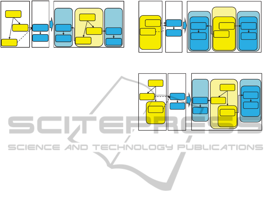
Figure 3: Static Multi-instance Partner Instantiation (left)
and Container Generation (right).
patterns described by Aalst et al. (van der Aalst et al.,
2003).
In static multi-instance creation scenarios, the
number of instances of multi-instance process to be
executed can be determined at design time. Static in-
stantiation can be either implemented by performing
exactly one instance of one or more possible starting
invokes
a
start
or by performing a fixed number of in-
stances of the same activity
a
start
, e. g., within a repeat-
able construct whose number of iterations is defined
at design time. In Figure 3 on the left two instances
of multi-instance process
P
Mi
are created when
a2
and
a3 are performed.
In dynamic multi-instance creation scenarios, the
number of instances of
a
start
is unknown at design
time but determined at runtime. Dynamic scenarios
can be implemented by repeatable constructs whose
number of iterations is only known at runtime such
as loops or event handlers. In this work, we focus
on
forEach
loops. The number of instances of the
activity “Send Price Request” that create an instance
of the “Airline” process is, for instance, determined
by the set of available airlines that is created during
runtime of activity “Determine Airlines”. Another
example of dynamic instance-creation is shown at the
left side of Figure 4. There, each activity instance
of
a2
and
a3
creates a process instance of
P
Mi
. The
number of instances of
P
Mi
depends on the number
of executed activity instances of
a2
and
a3
. That,
in turn, depends on the number of iterations of their
surrounding
forEach
loop whose upper bound
N
is
determined at runtime.
Also a combination of both instantiation ap-
proaches can be implemented, i. e., some instances
of multi-instance process are created statically while
others are created dynamically. An example for this hy-
brid instantiation approach is shown in Figure 5. Each
execution of activities
a2
,
a3
creates an instance of
P
Mi
, but the number of instances of
a4
to be executed
is not known at design time.
S
2
MiD
S
A
b1
Receive
a1
Parallel
ForEach
1..N
P
Mi
P
A
P
Merged
a2
Invoke
b2
Opaque
fe2
MP
Parallel
ForEach
0..N
syn1
rc
Empty
b2
Opaque
a3
Invoke
S
1
MiD
fe1
MP
Parallel
ForEach
0..N
syn2
RC
Empty
b2
Opaque
a1
Parallel
ForEach
1..N
syn1
s
Assign
syn2
s
Assign
Figure 4: Dynamic Multi-instance Partner Instantiation (left)
and Container Generation (right).
S
1
MiD
S
A
b1
Receive
P
Mi
P
A
P
Merged
b2
Opaque
a2
Invoke
l
1
l
2
a1
Opaque
S
1
MiS
b1
Empty
b2
Opaque
a2
Assign
l
1
l
2
a1
Opaque
b2
Parallel
ForEach
b1
Empty
c2
Opaque
a3
Parallel
ForEach
1..N
a4
Assign
a3
Parallel
ForEach
1..N
a4
Invoke
Figure 5: Hybrid Multi-instance Partner Instantiation (left)
and Container Generation (right).
4 MULTI-INSTANCE PROCESS
CONSOLIDATION
Based on the consolidation steps for single instance
interactions described in subsection 2.2, the control-
flow properties and the different approaches to initiate
multi-instance interactions described in section 3, the
consolidation approach for multi-instance interactions
is proposed in this section.
4.1 Container Generation
As described in subsection 2.2, in the second step of
the consolidation, for each process model
P
1
, . . . , P
n
to be merged a container
S
1
, . . . , S
n
(
scope
) is created
in
P
Merged
, where each container contains the respec-
tive activities of
P
1
, . . . , P
n
. This approach cannot be
directly applied for multi-instance processes as a (po-
tentially unknown) number of instances of activities
have to be executed during the execution of
P
Merged
that run simultaneously and isolated from each other.
We have to distinguish between the container gener-
ation for static multi-instance creation scenarios and
for dynamic multi-instance creation scenarios as in the
former scenario the number of activity instances to be
isolated is known while in the other case it is unknown.
During the execution of
C
, one static starting in-
voke activity
a
start
can potentially create one instance
of a multi-instance process by sending a message to an
activity
a
init
. To emulate this behavior, “multi-instance
Choreography-basedConsolidationofMulti-instanceBPELProcesses
291

process unrolling” is performed. That means, for each
static starting invoke
a
i
start
, a separate container
S
i
MiS
is created as immediate child activity of
P
Merged
. Even
though the invokes may be mutually exclusive, we
generate a container for each invoke. BPEL’s execu-
tion semantics (the dead path elimination) ensures that
the container is only executed if the invoke itself had
been executed. This also implies that for each activity
a
start
residing within a handler (fault handler, event
handler, ...), a container
CS
MP
is generated as they
may potentially be executed during the execution of
C
.
Thus, the number of static instantiation activities for
multi-instance process determines the number of con-
tainers
CS
MiS
that are generated within
P
Merged
. The
execution of the two static starting invoke activities for
P
Mi
a2
and
a3
in Figure 3 could be mutually exclusive
if the transition conditions of control links
l
1
and
l
2
always evaluate to different Boolean values or if both
links evaluate to false. Nevertheless, due to the over-
approximation the two containers
S
1
MiS
and
S
2
MiS
are
created in
P
Merged
. Creating a separate container
S
MiS
for each multi-instance process instantiation also en-
sures the same instance-independence of the activities
as in
C
. To perform the control flow materialization
correctly for each generated container
CS
MiS
, a new
set of message links is created.
As the number of instances of
a
start
cannot be de-
termined in dynamic multi-instance creation scenar-
ios, the number of process instances of multi-instance
process is not known at design time. Hence, the multi-
instance process cannot be “unrolled” into different
containers as in static multi-instance creation scenarios.
To emulate these scenarios in
P
Merged
, a container for
the activities of the multi-instance process is needed.
This container has to realize the simultaneous and iso-
lated execution of an at design time unknown number
of instances of the activities of the multi-instance pro-
cess. The only construct in BPEL supporting a simulta-
neous execution of a number of instances (branches) of
its root activities (along with its children) in an isolated
fashion is the parallel forEach activity. Therefore, for
each dynamic
a
start
, a dynamic container
scope S
MiD
is created that contains a parallel
forEach
activity
fe
MP
that contains the root activity of the multi-instance pro-
cess within its
scope
. The scope is required as BPEL
enforces the immediate child of a
forEach
loop being
a
scope
. This results in two levels of isolation: (i) the
scope within the
forEach
isolates the root activity in-
stances of the multi-instance process from each other
by catching all faults that may be thrown by them; (ii)
the scope
S
MiD
isolates
fe
MP
from the other containers.
Note that for each dynamic
a
start
, a separate dy-
namic container
S
MiD
is created. Even if
n
distinct
dynamic
a
start
activities that send a message to the
same instance-creating activity
a
init
are located within
the same parent loop as shown in Figure 4. The reason
for creating a separate dynamic container for each of
the
n
activities
a
1
init
, . . . , a
n
init
is that all or a subset of
the a
init
activities may be performed simultaneously.
The attribute values for
fe
MP
are defined as follows:
It gets the start and the final counter value of the parent
forEach of
a
start
and a unique id to distinguish it from
other forEach loops. The counter values are required
to assign data between the instances of the forEach
loop as described in subsection 4.4. It may happen
that
a
start
is not executed during each iteration due to
certain control flow conditions. Consequently, more
instances of
fe
MP
may be created than necessary. Due
to the synchronization activities that are created during
the control flow materialization, it is ensured that the
business activities in the “unused” instances are not
activated. The parent forEach of an
a
start
may have
a completion condition defined that specifies that the
processing of the forEach maybe ended as soon as
a subset of its branches completed successfully even
though there are still running branches. This condition
is not applied to
fe
MP
, because during the execution of
C
all instances of a multi-instance process that were
created are allowed to complete.
In the hybrid instantiation scenarios of multi-
instance processes, static and dynamic multi-instance
containers are created in
P
Merged
that contain the ac-
tivities of the multi-instance process. In Figure 5, the
static container
S
1
MiS
is created and the dynamic con-
tainer
S
1
MiD
for the instantiation activities
a2
and
a4
respectively.
Static and dynamic multi-instance containers are
started when
P
Merged
becomes active. However, the
business activities within the containers are not exe-
cuted until the incoming links are activated.
4.2 Control Flow Materialization
The basic concepts to materialize the control flow from
the message flow for single instance scenarios have
been described in subsection 2.2. These concepts can
be also applied to multi-instance scenarios since on the
instance level also one-to-one communication takes
place between the interacting processes. For instance,
in the example choreography in Figure 1, an instance
of the “Send Price Request” activity communicates
with exactly one instance of the “Rc Price Request”
activity. Therefore, we do not need to modify the con-
trol flow materialization for multi-instance scenarios,
neither for static, dynamic, nor hybrid instantiation
scenarios. Activities that were used in
C
to assign the
endpoint references (EPR) of the processes to be called
from the communication activities can be removed.
CLOSER2014-4thInternationalConferenceonCloudComputingandServicesScience
292

For instance, the activity “Determine Airlines” returns
a set of EPRs. In each iteration of “Collect Prices
FE” another airline EPR is assigned to “Send Price
Request”. This assignment is not shown in Figure 1.
The consolidated process model
P
Merged
created from
the example choreography is depicted in Figure 2.
4.3 Resolving Link Violations
If dynamic multi-instance containers are created, the
control flow materialization causes cross-boundary
link violations as the consolidation always gener-
ates control links between synchronization activi-
ties that cross boundaries of forEach loops. For in-
stance, the link
l1
from activity “syn
SendReq
” to activity
“syn
RcReq
” in Figure 2. To resolve these violations, the
link status value (“true” if the link is enabled, “false” if
it is disabled and “undef.” if undetermined) of “syn
s
”
to “syn
rc
” could be written to a new variable
v
ls
that
can be also accessed from within the loop to check
if “syn
rc
” can be started, i. e., if the link is enabled.
However, as from within the loop it is unknown when
v
ls
is set, another loop preceding “syn
rc
” is needed that
constantly polls the value of
v
ls
until it is set from “un-
def.” to “true” or to “false”. As the permanent polling
stresses the workflow engine and the underlying re-
sources, this solution is not an option. Of course, one
could adjust the polling interval but a useful polling
interval would have to be determined for each busi-
ness scenario to ensure the overall process execution
time is not negatively affected. Instead, we propose a
forEach loop fragmentation approach to resolve the
cross-boundary link violations. We also describe how
link status values can be propagated between the cre-
ated forEach loop fragments.
4.3.1 ForEach Loop Fragmentation
Each pair of activities “syn
s
” and “syn
rc
” violating the
cross-boundary link constraint is moved from its orig-
inal forEach loop into a new forEach loop
fe
syn
. By
convention,
fe
syn
is always placed into the container
scope
CS
of “syn
s
” to ensure that no data are copied by
“syn
s
” if another activity fails within
CS
. All opaque
activities directly or indirectly preceding “syn
s
” (but
no other synchronization activity) are moved from
their original forEach loop to a new FE-fragment
fe
pred
that is also created in the container scope of “syn
s
”.
The direct and indirect predecessor activities of “syn
rc
”
(if any) that do not precede another synchronization
activity and that were contained in the same original
forEach as “syn
rc
”, are moved to a new FE-fragment
fe
rc
. This FE-fragment must be created in the con-
tainer scope of “syn
rc
” as the opaque activities pre-
ceding “syn
rc
” originate from this container. The FE-
fragments
fe
syn
and
fe
rc
are connected via a control
link
l( f e
rc
, f e
syn
)
. This maintains the original exe-
cution order that defined that “syn
rc
” is not started
until its predecessors completed. Accordingly, FE-
fragment
fe
pred
is connected to
fe
syn
via control link
l( f e
pred
, f e
syn
)
to ensure that “syn
s
” is only started
after its predecessor activities completed. If “syn
s
”
had no predecessor activities in its original forEach,
fe
syn
is connected to the predecessor activities of the
original forEach of “syn
s
”. FE-fragment
fe
syn
is either
connected to the FE-fragment that contains the direct
successor activities of “syn
s
” or directly to its succes-
sor activities in case it does not reside within a forEach.
Additionally,
fe
syn
is connected to the forEach hosting
the direct successor activities of “syn
rc
” or directly to
the successor activities of “syn
rc
” that do not reside
within a forEach. All opaque activities that do not
precede any synchronization activity are left in their
corresponding original forEach loops and connected to
the
fe
syn
fragment that contains their preceding “syn
s
”
and “syn
rc
” respectively. Note, that all FE-fragments
that host opaque activities inherit the start and end
counter values of the forEach loop where the opaque
activities originate from. Also the fault handlers and
termination handlers are adapted from the original
forEach. FE-fragments
fe
syn
inherit the attributes and
handlers from
forEach syn
s
. The control links between
the activities within a FE-fragment are kept to main-
tain the execution order between these activities. All
incoming links of activities whose predecessors re-
side within another FE-fragment are removed. When
the successor activities of an activity were moved to
another FE-fragment its outgoing links are removed.
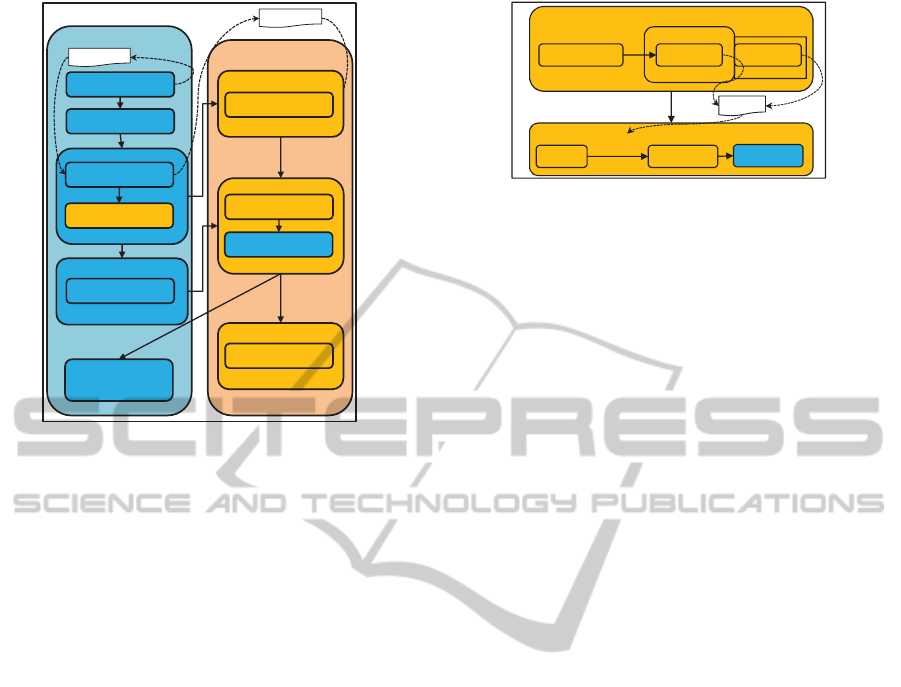
Figure 6 shows the fragmented version of
P
Merged
of
our example scenario. In the “Travel Agency” con-
tainer the two FE-fragments “CollectPricesFE
1
” and
“CollectPricesFE
2
” are created. The “Airline” con-
tainer hosts the activities “AirlineFE
1
” to “AirlineFE
3
”.
The control links between the FE-fragments and also
their preceding and succeeding activities are created
as described above.
4.3.2 Link Status Propagation
The split of the original forEach loops of
P
Merged
into
several FE-fragments causes control links to break if
activities
a
src
and
a
trg
that were connected via link
l(a
src
, a
trg
, tc)
(
tc
represents the transition condition
of the link) were placed into different FE-fragments
fe
m
and
fe
n
. Khalaf and Leymann (Khalaf and Ley-
mann, 2006) describe an approach to split a single
process into several individual process fragments. As
this also causes control links to break if the source
and target activity of a link reside within different
process fragments, they described a technique to prop-
Choreography-basedConsolidationofMulti-instanceBPELProcesses
293
Airline
Container Scope
Travel Agency
Container Scope
Determine Airlines
Opaque
CollectPricesFE
1
Parallel ForEach
syn
SendReq
Assign
Choose Cheapest
Airline & Book Ticket
Opaque
var: tripData
var: priceReq
Get Travel Request
Opaque
l1
P
Merged
CollectPricesFE
2
Parallel ForEach
Store Quote
Opaque
AirlineFE
2
Parallel ForEach
AirlineFE
1
Parallel ForEach
syn
RcReq
Empty
AirlineFE
3
Parallel ForEach
Calculate Price
Opaque
syn
SendQuote
Assign
Process Ticket Order
Opaque
syn
RcQuote
Empty
Figure 6: Fragmented Version of Consolidated Process
Model P
Merged
.
agate the link status from one process fragment to an-
other via message exchanges. We adapt this approach
to propagate the link status from one FE-fragment
to another by using variables instead of message ex-
changes. In the FE-fragment hosting
a
src
a new scope
S
ls
with a fault handler
FH
is added. To
S
ls
the as-
sign activity
assign
true
and to
FH
the assign activity
assign
f alse
is added.
assign
true
writes the link status
value “true” to a newly introduced variable
var
ls
that
resides in the parent scope of
fe
m
and
fe
n
.
assign
f alse
writes the link status value “false” to
var
ls
. A new
link
l
src
(a
src
, assign
true
, tc)
is created. The attribute
suppressJoinFailure within
S
ls
is set to “no”, i. e.,
when the transition condition
tc
evaluates to “false”
a bpel:joinFailure is thrown. This failure is caught by
FH
and
assign
f alse
is executed that writes the link sta-
tus value “false” to a newly created variable
var
ls
. If
tc
evaluates to “true”
assign
true
writes “true” to
var
ls
.
In the FE-fragment that hosts the link target
a
trg
a new
empty
activity
em
is created that is connected to
a
trg
via the new link
l
trg
(em, a
trg
, read(var
ls
))
. Thereby,
the function
read(var
ls
)
reads the link status of
var
ls
.
An instance of the
empty
activity
em
is started as soon
as the corresponding
forEach
branch becomes active.
As the execution order between activities
a
src
and
a
trg
is preserved by the execution order between their host-
ing FE-fragments, the value of
var
ls
is always set
before
em
is started. Figure 7 shows exemplary the
FE-fragments “AirlineFE
1
” and “AirlineFE
2
” with the
link propagation logic. To propagate the status of link
l3
from “Calculate Price” to “syn
SendQuote
” as in the
original unfragmented “AirlineFE” the status of the
outgoing link of “Calculate Price” is written to
var
l3
AirlineFE
2
Airline
AirlineFE
1
CalculatePrice
syn
SendQuote
S
ls3
Scope
assignL3
true
assignL3
false
FH
empty
l3
'true'
'false'
read(var
l3
)
l3
l3'
var
l3
syn
SendQuote
Figure 7: Passing Link Status Values Between FE-
Fragments.
by “assignL3
true
” and “assignL3
false
” respectively, de-
pending on the status of
l3
in “AirlineFE
1
”. This status
is then applied to the new link
l3
0
in
AirlineFE2
by
reading
var
l3
. The link propagation approach does also
ensure that death-path elimination can be performed.
If, for instance, the incoming link of “Calculate Price”
evaluates to “false” and “syn
SendQuote
” had any outgo-
ing links (which is not the case in the example), the
outgoing links of “syn
SendQuote
” are automatically set
to “false”.
So far, we regarded one variable
var
ls
, where the
link status is written to and read from. However, since
multiple instances of the same link are created, also
multiple instances of link status values must be hold.
Therefore,
var
ls
has to be extended to hold multiple
status values of the same link and also assign activ-
ities have to be modified accordingly to access the
correct instance of a link status. This is described in
subsection 4.4.
4.4 Data Flow
As described in subsection 2.2, the variables have to
be globalized to the process scope of
P
Merged
for shar-
ing data between different container scopes
CS
. To
share data and link status values between different
FE-fragments that originate from the same forEach,
these variables have to be lifted to the parent container
scope
CS
MiD
of the FE-fragments. In contrast to the
one-to-one interaction scenarios during choreography
runtime, several instances of the same variable are cre-
ated, e. g., for each “Airline” partner, one instance of
the variable “priceReq”. We refer to these variable
as “multi-instance variables”
V
MI
. To store multiple
instances of a variable
v
MI
, it is replaced by a map
mp
MI
. Each entry of
mp
MI
represents an instance of
v
MI
, i. e., the entries of
mp
MI
inherit the data type of
the original
v
MI
and can be uniquely identified by a key
key
IID
(instance id) of type
<xsd:id/>
that represents
an instance of v
MI
.
This raises the question how the
key
IID
is com-
posed, how a branch (instance) of a FE-fragment can
be related to a certain entry in
mp
MI
via
key
IID
and
CLOSER2014-4thInternationalConferenceonCloudComputingandServicesScience
294

how to ensure that data can be shared between differ-
ent FE-fragments. Intuitively, EPRs could be used to
compose keys as they are also employed in
C
to iden-
tify an instance of a multi-instance process. However,
there is technically no way to inject a key such as an
EPR into a forEach branch from outside to a specific
instance when it starts. Thus, a forEach branch is not
aware of what key it is related to. Therefore, a con-
vention is needed to enable the branch to determine
its associated key by itself. The only information that
uniquely identifies a forEach branch among the other
branches and that does not change during its lifetime is
the value of the instance counter variable. As different
forEach loops are contained within
P
Merged
, their in-
stance counter values are not globally unique but only
within the respective forEach. To ensure global unique-
ness and to share data between the same branches (i. e.,
branches with the same counter value) of FE-fragments
that originate from the same forEach loop, the static
id
feid
(defined at design time) and the dynamic in-
stance counter value
iid
(defined at runtime) are con-
catenated. Note, that all FE-fragments that originate
from the same forEach share the same
feid
. Assume,
for instance, that the execution of three instances of the
“Airline” process has to be emulated. The first instance
would get the instance key “AirlineFE 1”, the second
“AirlineFE 2” and so on. Similarly, three instances of
the forEach “CollectPricesFE” would get the instance
keys “CollectPricesFE 1” to “CollectPricesFE 3”. As
described in subsection 4.1,
fe
MI
inherits the start
and end counter value of the parent forEach of
a
start
(e. g., “AirlineFE” has the same start and end counter
values as “CollectPricesFE”). Also the different FE-
fragments inherit the values of the forEach loops they
were created from. Since all of these FE-fragments
share the same start and end counter variables, their
branches can be logically related to each other by using
their instance id
iid
, e. g., branch “CollectPricesFE 1”
can be related to “AirlineFE 1”, “CollectPricesFE 2”
to “AirlineFE 2” etc. Data can be passed between
all logical related FE-fragments by rewriting assign
statements and transition conditions accessing multi-
instance variables
v
MI
. As these variables are always
located within FE-fragments, data accesses to
v
MI
can
be rewritten during the consolidation to data accesses
to those entries of mp
MI
that share the same iid.
5 DISCUSSION
In this section the properties of a process
P
Merged
cre-
ated by applying the multi-instance process consolida-
tion approach proposed in section 4 are discussed.
The consolidation maintains the control flow con-
straints defined in
C
. On the one hand, the original
control links between activities moved to the same FE-
fragment (e. g., “syn
SendQuote
” and “syn
RcQuote
” in FE-
fragment “AirlineFE
2
”) are maintained. One the other
hand, the execution order between consecutive activi-
ties
a
i
and
a
j
moved to different FE-fragments is kept
by connecting the FE-fragments based on the control
relation between
a
i
and
a
j
. The proposed propagation
technique for link status values guarantees that activi-
ties are only executed if their incoming links evaluate
to “true” even if link source activity resides within an-
other FE-fragment. Since the fault handler and termi-
nation handler from the original
forEach
are attached
to the FE-fragments and since the FE-fragments are ex-
ecuted sequentially the fault handling and semantics of
BPEL is also kept, i. e., if within a certain FE-fragment
branch an activity fails, all running activities within
this branch are terminated and activities within the
succeeding FE-fragment branches that represent the
same instance (i. e., branches with the same instance
counter value iid) are not started anymore.
The consolidation keeps the control flow con-
straints modeled in
C
. However,
P
Merged
cannot gen-
erate all execution traces between business activities
that could be generated by
C
. The reason is that the
multi-partner instances lose their instance autonomy
from each other. The instance autonomy is lost, be-
cause of the FE-fragmentation. Assume, for instance,
the execution time of activity “Calculate Price” in the
choreography in Figure 1 depends on the input data,
i. e., the price request. Then, depending on the request,
the instance “Calculate Price
i
” is long running while
in another instance “Calculate Price
j
” is short running.
Therefore, the succeeding activity instances of “Calcu-
late Price
i
” would be started earlier as those of “Calcu-
late Price
j
”. If all succeeding activity instances
i
and
j
would need the same execution time, all activity in-
stances
i
would be completed before activity instances
j
. The FE-fragmentation, however, imposes also con-
trol flow relations between different instances that are
emulated. This is due to the fact, that all branches
of a forEach, i. e., an FE-fragment, have to be com-
pleted until the succeeding FE-fragment can be started.
Hence, no instance of “syn
SendQuote
” is started until all
instances of “Calculate Price” completed as the emu-
lated instances have to “wait” for each other. This can
significantly increase the time until a business goal is
reached, especially, if the execution times of individ-
ual instances of the same activity are highly different
and if only a subset of instances is required for fulfill-
ing the business goal (e. g., the “Travel Agency” may
only need the response from three out of 10 airlines).
However, if
C
and
P
Merged
are started with the same
input data, their overall execution time is the same, as
Choreography-basedConsolidationofMulti-instanceBPELProcesses
295

in both case all business activity instances (that are
activated via a path) have to be executed. If we have
just static multi-instance scenarios where
a
start
does
not reside within a forEach loop, we do not encounter
the problem of losing instance autonomy that was de-
scribed above. That is the reason why we distinguish
between these scenarios.
The multi-instance consolidation may lead to a
complex process
P
Merged
. This is because the multi-
instance process unrolling and the forEach fragmenta-
tion create many new activities and the corresponding
control links in
P
Merged
. Hence, the maintainability
of
P
Merged
is decreased, i. e., the process structure is
difficult to understand. This, in turn, makes it very
difficult to change the process. For that reason we
recommend that the consolidation should be applied
when the choreography is not changed anymore. For
instance at deployment time the choreography can be
consolidated to save resources (refer to section 1). To
monitor the state of the original choreography state
propagation rules can be used that derive the state
of the choreography from from the runtime state of
P
Merged
(Wagner et al., 2012a).
6 IMPLEMENTATION
In previous work (Debicki, 2013) a Java prototype was
developed that gets a BPEL4Chor choreography as
input and returns the consolidated process model in
BPEL. The consolidated process model can then be
deployed on a workflow engine (Wagner et al., 2013b).
Initially the prototype implemented the consoli-
dation steps for one-to-one interactions described in
subsection 2.2. For evaluation of the multi-instance
process consolidation approach described in section 4
it was extended (Dadashov, 2013) to create multi-
instance containers in
P
Merged
, to perform the forEach
loop fragmentation and to create multi-instance vari-
ables.
Internally, the prototype performs the consolida-
tion steps on a BPEL4Chor EMF
1
object model
2
which is an extension of the Eclipse BPEL EMF
model
3
. The EMF models provide Java object se-
rializations of BPEL processes and BPEL4Chor chore-
ographies respectively. To consolidate interacting pro-
cesses the prototype reads a ZIP file that contains the
XML representations of the participant topology and
the participant behavior descriptions. These XML rep-
resentations are transformed into a BPEL4Chor EMF
1
http://www.eclipse.org/modeling/emf/.
2
https://github.com/IAAS/BPEL4Chor-model.
3
http://www.eclipse.org/bpel/developers/model.php.
model and a new BPEL EMF model for
P
Merged
is gen-
erated. Then the prototype inspects the BPEL4Chor
EMF model to determine the container scopes to be
generated in
P
Merged
and to perform the control flow
materialization. After the consolidation operations
completed
P
Merged
is transformed back into a BPEL
schema-compliant XML. A process modeler has to
replace the
opaque
activities in
P
Merged
(if any) by exe-
cutable activities (executable completion (Aalst et al.,
2008)). As deployment descriptors a workflow engine
specific the process modeler also has to add them man-
ually after the consolidation completed. Then
P
Merged
can be deployed.
7 RELATED WORK
Mendling and Simon (Mendling and Simon, 2006) pro-
pose an approach where semantically equivalent events
and functions of Event Driven Process Chains (Scheer
et al., 2005) are merged. K
¨
uster et al. (K
¨
uster et al.,
2008) describe how change logs can be employed to
merge different process variants that were created from
the same original process. These approaches merge
processes that are semantically equivalent or that are
different variants of the same original process. Our
approach focuses on the consolidation of collaborat-
ing processes into a single process model. Moreover,
none of these approaches deals with multi-instance
interactions.
An alternative way to generate a BPEL orches-
tration of a BPEL4Chor choreography is using an
intermediate format. However, there is currently no
approach keeping the structure of the generated orches-
tration close to the structure of the original choreogra-
phy. For instance, Lohmann and Kleine (Lohmann
and Kleine, 2008) do not generate BPEL scopes
out of Petri nets, even if the formal model of
Lohmann (Lohmann, 2007) generates a Petri net rep-
resentation of BPEL scopes.
There are other ways to describe inter-
organizational collaboration. For instance, the
lifecycle of a business entity can be put into the center
of modeling (Hull et al., 2011). In this paper, we did
not follow that approach, but used the interconnection
model choreography approach.
8 CONCLUSION AND OUTLOOK
In this paper, we introduced an approach to consoli-
date BPEL processes interacting with multi-instance
processes in a choreography into a single process
model that emulates the multi-instance behavior of
CLOSER2014-4thInternationalConferenceonCloudComputingandServicesScience
296

the original choreography. To perform the consoli-
dation, we distinguished three instantiation scenarios
for the multi-instance processes. In static instanti-
ation scenarios, the number of instances can be de-
termined during the consolidation. To emulate the
static multi-instance scenarios, for each possible in-
stance, a separate container containing activities of
the multi-instance process is created within the con-
solidated process. In dynamic instantiation scenarios,
the number of instances cannot be determined during
the consolidation. To emulate this scenario, the ac-
tivities of multi-instance processes are copied into a
parallel forEach loop whose number of iterations is
determined during runtime. Each branch of this loop
emulates one instance of the multi-instance process.
The control flow materialization may create control
links from the message links that cross the boundaries
of the forEach loop what is not permitted in BPEL. To
resolve these violations we proposed a technique to
sequentially split the forEach loop into different frag-
ments. We also discussed how the data flow within the
consolidated process model has to be modified to store
and access multiple instances of the same variable.
Currently, we do only support consolidation of
multi-instance processes that are instantiated by an
instance creating activity that resides in a forEach loop.
In the future also the consolidation of multi-instance
processes is supported that are instantiated from within
nested and condition-controlled loops such as while
loops.
Reference passing is an additional major aspect
of multi-instance interactions, e. g., the travel agency
could pass the endpoints of the three cheapest airlines
to a traveler process who then decides by itself what
airline is booked. Our approach has to be extended
accordingly to support these interaction scenarios as
they are very common in the context of multi-instance
processes. We also have to discuss more in depth how
BPEL’s compensation handling mechanism is affected
by the split of a single forEach into different fragments.
As shown by Wagner et al. (Wagner et al., 2013b),
the execution time and performance overhead of a
choreography execution can be significantly reduced
if its processes are consolidated into a single process
model, because message serialization, message trans-
port, and message de-serialization is avoided. In fu-
ture work, we have to analyze the performance dif-
ferences between consolidated process models that
emulate multi-instance processes and their original
choreography.
As BPMN becomes more and more important and
since it shares a lot of concepts and language con-
structs with BPEL and BPEL4Chor, we have to inves-
tigate how our consolidation approach can be applied
to merge BPMN collaboration diagrams.
ACKNOWLEDGEMENTS
This work was partially funded by the BMWi project
Migrate! (01ME11055) and the BMWi project Cloud-
Cycle (01MD11023).
REFERENCES
Aalst, W. M. P. v. d., Lohmann, N., Massuthe, P., Stahl,
C., and Wolf, K. (2008). Multiparty contracts: Agree-
ing and implementing interorganizational processes.
Comput. J., 53(1):90–106.
Barros, A., Decker, G., Dumas, M., and Weber, F. (2007).
Correlation patterns in service-oriented architectures.
In FASE, volume 4422. Springer.
Barros, A., Dumas, M., and ter Hofstede, A. (2005). Service
Interaction Patterns. In BPM. Springer.
B
¨
orger, E. (2012). Approaches to modeling business pro-
cesses: a critical analysis of bpmn, workflow patterns
and yawl. Softw. Syst. Model., 11(3):305–318.
Dadashov, E. (2013). Choreography-based Business Process
Consolidation in One-To-Many interactions. Master
thesis, University of Stuttgart, Faculty of Computer
Science, Electrical Engineering, and Information Tech-
nology, Germany.
Debicki, P. (2013). Choreographie-basierte Konsoliedierung
von BPEL Prozessmodellen. Diploma thesis, Univer-
sity of Stuttgart, Faculty of Computer Science, Elec-
trical Engineering, and Information Technology, Ger-
many.
Decker, G., Kopp, O., and Barros, A. (2008). An Introduc-
tion to Service Choreographies. Information Technol-
ogy, 50(2):122–127.
Decker, G., Kopp, O., Leymann, F., and Weske, M. (2009).
Interacting services: From specification to execution.
Data & Knowledge Engineering, 68(10):946–972.
DeRemer, F. and Kron, H. (1976). Programming-in-the-large
versus programming-in-the-small. Software Engineer-
ing, IEEE Transactions on, SE-2(2):80 – 86.
Hull, R., Damaggio, E., Fournier, F., Gupta, M., Heath,
F. T., Hobson, S., Linehan, M., Maradugu, S., Nigam,
A., Sukaviriya, P., et al. (2011). Introducing the guard-
stage-milestone approach for specifying business entity
lifecycles. In 7
th
International Workshop, WS-FM
2010, LNCS. Springer-Verlag.
Khalaf, R. and Leymann, F. (2006). Role-based Decomposi-
tion of Business Processes using BPEL. In ICWS 2006.
IEEE.
Khalaf, R. and Leymann, F. (2010). Coordination for Frag-
mented Loops and Scopes in a Distributed Business
Process. In BPM. Springer.
Kopp, O., Eberle, H., Leymann, F., and Unger, T. (2010).
The Subprocess Spectrum. In Proceedings of the
Business Process and Services Computing Conference:
BPSC 2010. GI e.V.
Choreography-basedConsolidationofMulti-instanceBPELProcesses
297

Kopp, O., Martin, D., Wutke, D., and Leymann, F. (2009).
The Difference Between Graph-Based and Block-
Structured Business Process Modelling Languages. En-
terprise Modelling and Information Systems, 4(1):3–
13.
Kossak, F., Illibauer, C., and Geist, V. (2012). Event-
based gateways: Open questions and inconsistencies.
In Mendling, J. and Weidlich, M., editors, Business
Process Model and Notation, volume 125 of Lecture
Notes in Business Information Processing, pages 53–
67. Springer Berlin Heidelberg.
K
¨
uster, J., Gerth, C., F
¨
orster, A., and Engels, G. (2008). A
tool for process merging in business-driven develop-
ment. In Proceedings of the Forum at the CAiSE.
Leymann, F. (2010). Bpel vs. bpmn 2.0: Should you care?
In BPMN, pages 8–13.
Lohmann, N. (2007). A Feature-Complete Petri Net Seman-
tics for WS-BPEL 2.0. In WS-FM.
Lohmann, N. and Kleine, J. (2008). Fully-automatic Trans-
lation of Open Workflow Net Models into Simple Ab-
stract BPEL Processes. In Modellierung. GI e.V.
Mendling, J. and Simon, C. (2006). Business process design
by view integration. In BPM Workshops. Springer.
OASIS (2007). Web Services Business Process Execution
Language Version 2.0 – OASIS Standard.
Object Management Group (OMG) (2011). Business Pro-
cess Model and Notation (BPMN) Version 2.0. OMG
Document Number: formal/2011-01-03.
Scheer, A.-W., Thomas, O., and Adam, O. (2005). Process
Aware Information Systems: Bridging People and Soft-
ware Through Process Technology, chapter Process
Modeling Using Event-Driven Process Chains. Wiley-
Interscience.
van Breugel, F. and Koshkina, M. (2006). Models and Veri-
fication of BPEL. http://www.cse.yorku.ca/ franck/re-
search/drafts/tutorial.pdf.
van der Aalst, W. M. P., ter Hofstede, A. H. M., Kie-
puszewski, B., and Barros, A. P. (2003). Workflow
Patterns. Distributed and Parallel Databases, 14(1):5–
51.
Wagner, S., Fehling, C., Karastoyanova, D., and Schumm,
D. (2012a). State Propagation-based Monitoring of
Business Transactions. In Proceedings of the 2012
IEEE International Conference on Service-Oriented
Computing and Applications. IEEE Xplore.
Wagner, S., Kopp, O., and Leymann, F. (2011). To-
wards Choreography-based Process Distribution In The
Cloud. In CCIS.
Wagner, S., Kopp, O., and Leymann, F. (2012b). Towards
Verification of Process Merge Patterns with Allen’s
Interval Algebra. In ZEUS. CEUR.
Wagner, S., Kopp, O., and Leymann, F. (2013a). Consoli-
dation of Interacting BPEL Process Models with Fault
Handlers. In Proceedings of the 5th Central-European
Workshop on Services and their Composition (ZEUS
2013), pages 1–7, Rostock. CEUR Workshop Proceed-
ings.
Wagner, S., Roller, D., Kopp, O., Unger, T., and Leymann,
F. (2013b). Performance optimizations for interacting
business processes. In IC2E. IEEE.
Wohed, P., van der Aalst, W. M. P., Dumas, M., ter Hofstede,
A. H. M., and Russell, N. (2006). On the suitability
of bpmn for business process modelling. In Business
Process Management, pages 161–176.
CLOSER2014-4thInternationalConferenceonCloudComputingandServicesScience
298
