
A Bottom Up SPL Design Method
Jihen Maazoun
1
, Nadia Bouassida
2
and Han
ˆ
ene Ben-Abdallah
3
1
Mir@cl Laboratory, Facult
´
e des Sciences Economiques et de Gestion , Sfax University, Sfax, Tunisia
2
Institut Sup
´
erieur d’Informatique et de Multim
´
edia, Sfax University, Sfax, Tunisia
3
FCIT, King Abdulaziz University, Jeddah, Kingdom of Saudi Arabia
Keywords:
SPL Design, UML Profile, FCA, LSI.
Abstract:
Software Product Lines (SPL) ensure predictive and organized software reuse. In practice, SPL are often set
up after several similar product variants have been in use. This practical fact prompted a quest for bottom-up
processes that start from existing the source of product variants to identify a product line. This later is then
described with a feature model that essentially specifies the components of the SPL and their variability within
the product family. However, so far proposed notations for feature models do not provide for a clear under-
standing of the SPL nor do they guide in their maintenance and future evolution. These shortages motivated
us to propose a bottom-up approach that extracts from the source code of product variants, the SPL design en-
riched with information extracted from the feature model. The enriched SPL is modeled with a UML profile
that assists in the comprehension, reuse as well as evolution of the SPL.
1 INTRODUCTION
The engineering techniques of Software Product
Lines (SPL) create a set of similar software systems
from a shared set of software assets. An SPL is con-
sidered as a set of systems that share a group of man-
ageable features. A feature is a prominent or dis-
tinctive quality or characteristic of a software system
or systems (Kang et al., 1990). Note that a feature
can be either simple/elementary like a package and a
class, or composed of several elements like (package,
class), (package, class, attribute, method)... An SPL is
modeled by a feature model which, as introduced by
the FODA method (Kang et al., 1990) and by (Czar-
necki and Eisenecker, 2000), represents a hierarchy of
properties of domain concepts. A feature model can
be derived through SPL development processes either
in top-down (cf., (Ziadi, 2004)) or a bottom-up (cf.,
(Ziadi et al., 2012) (She et al., 2011), (Al-Msie’Deen
et al., 2012)) approach. A top-down development pro-
cess starts with a domain analysis to construct the fea-
ture model of an SPL; it is often used for not well ex-
plored application domains and requires a high exper-
tise in the application domain. In contrast, a bottom-
up process identifies the mandatory and variable fea-
tures from the source code of a set of product variants
belonging to the same domain.
All SPL developed using bottom-up processes
lack the necessary documentation for their mainte-
nance and future evolution . In fact, they are accom-
panied only by their feature models which, in par-
ticular, have no traceability with the design of the
product variants. Consequently, when an SPL must
be maintained (e.g., emergence of new requirements,
improvement of existing features, disappearance of
some features,...), developers end-up spending time
to first rediscover the structure and behavior of the
SPL. As a consequence, it is necessary to have a de-
sign that accompanies FM and source code to facili-
tate their comprehension and evolution. These short-
ages motivated us to propose a bottom-up approach
that extracts from the source code of product variants
the SPL design enriched with information extracted
from the feature model. The enriched SPL is modeled
with a new UML profile that assists in the compre-
hension, reuse as well as evolution of the SPL. The
UML profile, called SPL-UML, enriches the UML
diagrams with information extracted from the fea-
ture model and highlights the variability of the SPL.
It integrates also OCL (Object-Constraint Language)
constraints ensuring the consistency off the variation
points.
In addition to the presentation of the SPL-UML
notation, this paper also proposes a bottom-up SPL
design method that adapts our approach for extracting
feature models from product source code(Maazoun
309
Maâzoun J., Bouassida N. and Ben-abdallah H..
A Bottom Up SPL Design Method.
DOI: 10.5220/0004707903090316
In Proceedings of the 2nd International Conference on Model-Driven Engineering and Software Development (MODELSWARD-2014), pages 309-316
ISBN: 978-989-758-007-9
Copyright
c
2014 SCITEPRESS (Science and Technology Publications, Lda.)

et al., 2013). The adapted method extracts both the
feature model and SPL-UML design from the exist-
ing product source codes. To do so, it first applies
reverse engineering techniques to extract the design
(class and sequence diagrams) of the different prod-
ucts. Secondly, it uses the Formal Concept Analysis
(FCA)(Ganter and Wille, 1996) technique to unify the
design of the different products and to extract the de-
sign of the SPL. At the same time, our method uses
the FCA and LSI (Latent Semantic Indexing) (Bink-
ley and Lawrie, 2011) techniques to extract the fea-
ture model from the source code of the product vari-
ants. Finally, the design of the SPL is enriched with
the information contained in the feature model and
it is represented in SPL-UML. The originality of our
bottom-up process is that it extracts a feature model
and a SPL design from source code that may have dif-
ferent vocabulary and structures.
The rest of this paper is organized as follows.
Section 2 first overviews existing works interested in
the extraction of SPL from product source code; sec-
ondly, it presents existing UML profiles for SPL de-
scription. Section 3 describes the proposed UML pro-
file for SPL in terms of stereotypes and tagged values.
Section 4 presents our method for SPL design extrac-
tion from product source codes and feature models.
In addition, it illustrates the method through an exam-
ple of an SPL for mobile phones. Finally, Section 5
summarizes the paper and outlines future work.
2 RELATED WORK
To motivate our design process and UML notation for
SPL, we briefly overview, in this section, bottom up
processes and UML profiles for SPL.
2.1 Existing Bottom-up Extraction
Processes
Several works investigated feature model extraction
from the source code of products in order to construct
an SPL ((Ziadi et al., 2012), (Al-Msie’Deen et al.,
2012),(Riebisch, 2003), (Nan and Steve, 2009)). For
instance, Ziadi et al, (Ziadi et al., 2012) propose
an approach that first abstracts the input products in
SoCPs (Sets Of Construction Primitives) and, sec-
ondly, it identifies features by determining common
and intersecting SoCPs. The obtained results show
that the approach can handle products with variable
names for classes, methods and attributes. However,
this approach produces a feature model which con-
tains only one mandatory feature and the others are
considered as optional features. Thus, it identify nei-
ther separated mandatory features, nor alternative fea-
tures and their related constraints such as the mutual
exclusion.
On the other hand, Al-Msiedeeen (Al-Msie’Deen
et al., 2012) propose an approach based on the defini-
tion of the mapping model between OO elements and
feature model elements. This approach uses FCA to
cluster similar OO elements into one feature. It uses
LSI to define a similarity measure based on which the
clustering is decided. This approach improves the ap-
proach of Ziadi (Ziadi et al., 2012) since it extracts
mandatory features and optional features along with
some constraints among features like And and Re-
quire. However, it does not treat product variants with
different structures or different terminologies. Mo-
rover, l-Msiedeeen (Al-Msie’Deen et al., 2012) does
not extract the design which facilite the comprehen-
sion of SPL.
Salman et al, (Salman et al., 2012) present a ge-
netic algorithm to recover traceability links between
feature models and source code. Traceability links
in SPL are needed to relate variation points and vari-
ants with all corresponding low level artifacts (re-
quirements, design, source code and test cases arti-
facts). The genetic algorithm can determine approxi-
mately the implementation of each feature (by linking
the feature to classes). However, it generates just one
solution for each run, and the number of runs neces-
sary to determine all possible classes for each feature
is unknown.
All of the approaches in (Ziadi et al., 2012), (Al-
Msie’Deen et al., 2012), (Salman et al., 2012) rely
on one underlying hypothesis: all source codes use
the same vocabulary and they have the same struc-
ture. That is, these approaches cannot be applied in
the derivation of SPL from product variants that were
produced by different developers. Moreover, in case
of maintenance or evolution, all feature models ex-
tracted in these works do not provide sufficient infor-
mation because the source product designs are totally
ignored. Such lost information would have to be re-
discovered by the developers in order to understand
the behavior and structure of the system.
2.2 Existing UML Profiles for SPL
Several studies (e.g., (ClauB, 2005) , (Ziadi, 2004),
(Gomaa, 2005)) have been interested in modeling
product lines with UML 2.0, the standard for object-
oriented analysis and design. In particular, they fo-
cused on defining profiles to manage the concept of
variability in the SPL. The proposed UML profiles
contain stereotypes, tagged values and constraints that
MODELSWARD2014-InternationalConferenceonModel-DrivenEngineeringandSoftwareDevelopment
310

can be used to extend the UML meta-model.
Claub (ClauB, 2005) proposes a UML profile
that extends the meta-model of the UML class dia-
gram with the stereotypes <<variationPoint>> and
<<variant>>. The optionality of a model element
can be expressed with the stereotype <<optional>>.
Moreover the profile provides values for specifying
the time in which the variability and optionality will
be included in the design of the product line. Meta-
classes extended by these stereotypes are: Class,
Component, Package, collaboration and association.
This work is a purely static approach and does not in-
clude proposals for behavioral modeling.
The Triskell team in (Ziadi, 2004) proposed a sim-
ilar approach and added an extension of the meta-
model of the sequence diagram. For the static aspect,
the authors proposed a set of stereotypes for the class
diagram (Optionality, Variation, Variant). For the dy-
namic aspect, the authors proposed a set of stereo-
types for the sequence diagram (optionalLifeline, op-
tionalInteraction, variation, variant).
Overall, existing UML profiles propose exten-
sions that illustrate the variability of SPL. However,
they focused essentially on the design without con-
sidering the feature model and did not add features in-
formation to their diagrams. This information is very
useful in case of feature evolution.
3 SPL-UML: A PROFILE FOR
SOFTWARE PRODUCT LINES
In this section, we present our UML profile named
SPL-UML.
3.1 Extensions for Class Diagrams
In the context of SPL, we propose to introduce dif-
ferent types of variabilities that are modeled using the
following stereotypes:
• <<optional>> is used to specify optionality in
UML class diagrams. The optionality can concern
classes, packages, attributes or operations.
• <<recommended>> is used to specify recom-
mendation in UML class diagrams. The recom-
mendation stereotype applies for classes only.
• <<mandatory>> is used to specify obligatory
elements in UML class diagrams. The obliga-
tory stereotype can concern classes, packages, at-
tributes or operations.
• <<mandatory
association>> is used to specify
obligatory relation between classes in UML class
diagrams. It is represented by bold line.
• <<optional association>> is used to specify op-
tionality relation between classes in UML class
diagrams. It is represented by dashed line.
• <<Xor association>> is used to specify an al-
ternative relation between classes in UML class
diagrams.
• <<Feature Name>> is used to specify in which
feature it is. The stereotype can concern classes,
packages, attributes or operations.
3.2 Extensions for Sequence Diagrams
In our profile, The UML sequence diagram is ex-
tended with the following stereotypes:
• <<optional>> is used to specify optionality in
UML sequence diagrams. The optionality can
concern objects, actors or operations.
• <<mandatory>> is used to specify obligatory
elements in UML sequence diagrams. The oblig-
atory stereotype can concern objects, actors or op-
erations.
• <<mandatory relation>> is used to specify
obligatory relations between objects, actors. It is
represented by bold line.
• <<optional relation>> is used to specify option-
ality between objects, actors. It is represented by
dashed line.
• <<Xor relation>> is used to specify an alterna-
tive relation between objects, actors (ifelse). It is
represented by solid line.
• <<Feature Name>> is used to specify in which
feature it is. The stereotype can concern objects,
actors.
3.3 Definition of OCL Constraints
The introduction of variability using new stereotypes
improves genericity but can generate some inconsis-
tencies (e.g., if a mandatory subclass specializes an
optional super class, the resulting model is incoher-
ent). Thus, in order to ensure SPL design consistency,
we define some OCL constraints that are applied to
structural and behavioral views of SPL design.
C1: Each package, class, method, attribute or as-
sociation in an optional feature, must be stereotyped
<<Optional>>
Context Feature inv self.isStereotyped
("Optional") implies self.package
− >forAll ((p|p.package.isStereotyped
("Optional") or (p|p.package.isStereotyped
ABottomUpSPLDesignMethod
311

("mandatory")) and self.class
− >forAll ((c|c.class.isStereotyped
("Optional") or (c|c.class.isStereotyped
("mandatory")) and self.method − >forAll
((m|m.method.isStereotyped ("Optional") or
(m|m.method.isStereotyped ("mandatory")
)and self.attribute − >forAll
((a|a.attribute.isStereotyped ("Optional")
or (a|a.attribute.isStereotyped
("mandatory")) and
self.association − >forAll
((as|as.association.isStereotyped
("Optional") or
(as|as.association.isStereotyped
("mandatory"))
C2:Each package, class, method, attribute or as-
sociation in a mandatory feature, must be stereotyped
<<Optional>> or <<Mandatory>>
Context Feature inv self.isStereotyped
("mandatory") implies self.package
− >forAll ((p|p.package.isStereotyped
("Optional") or (p|p.package.isStereotyped
("mandatory")) and self.class
− >forAll ((c|c.class.isStereotyped
("Optional") or (c|c.class.isStereotyped
("mandatory"))and self.method
− >forAll ((m|m.method.isStereotyped
("Optional") or (m|m.method.isStereotyped
("mandatory") )and self.attribute
− >forAll ((a|a.attribute.isStereotyped
("Optional") or
(a|a.attribute.isStereotyped("mandatory"))
and self.association − >forAll
((as|as.association.isStereotyped
("Optional") or
(as|as.association.isStereotyped
("mandatory"))
Overall, our SPL-UML profile dif-
fers from existing profiles by introducing
new steretypes like <<recommended>>,
<<mandatory association>>,
<<optional association>>, <<feature name>>.
Moreover, it defines OCL constraints which can be
applied to structural and behavioral views.
4 SPL DESIGN EXTRACTION
The SPL-UML notation will be used to describe
SPL designs extracted through our bottom-up process
which extracts, from the source code of product vari-
ants, the SPL design enriched with information ex-
tracted from the feature model. Our approach (illus-
trated in figure 1) contains four steps (Name harmo-
nization, Reverse engineering, Feature model extrac-
tion and Design elements extraction and SPL design
construction) which we detail next.
4.1 Name Harmonization
This pre-processing step starts by identifying the se-
mantic correspondences between the names of pack-
ages, classes, methods and attribute names through
interrogating WordNet. The semantic relations are
examined in the following order: the equivalence
(Synonyms), the string extension (Meronyms), and
then the generalization (Hypernyms)(Maazoun et al.,
2013):
• Synonyms(C1,···,Cn): implies that the names are
either identical or synonym, e.g., Mobile-Mobile
and Phone-Mobile.
• Hypernyms(C1; C2,···,Cn): implies the name C1
is a generalization of the specific names C2 ,···,
Cn, e.g., Media-Video.
• Meronyms(C1; C2): implies that the name C1 is a
string extension of the name of the class C2, e.g.,
Image-NameImage.
The determination of the above linguistic/semantic re-
lationships can be handled through either a dictionary
(e.g., Wordnet), or a domain ontology when available.
At the end of the pre-processing step, all seman-
tically related names would be harmonized and can
then be analyzed through the FCA in the features
identification step.
4.2 Reverse Engineering
Once the names are harmonized, we reverse engineer
the code to construct the class and sequence diagrams
required in the feature extraction step of our process.
A class diagram contains all classes and enumerates
the relationships between them (association, inheri-
tance, composition, aggregation). A sequence dia-
gram contains Lifelines, message, operation, object...
In our current prototype environment, the class
and sequence diagrams are re-engineered using the
plug-in eUML for eclipse.
4.3 Feature Model Extraction
In this step, we use FCA and LSI to extract the
commonalities and variability among the harmonized
product variants. Before explaining this step, let us
first overview the basics of FCA and LSI. FCA (Gan-
ter and Wille, 1996) is a method of data analysis,
whose main idea is to analyze data described through
MODELSWARD2014-InternationalConferenceonModel-DrivenEngineeringandSoftwareDevelopment
312
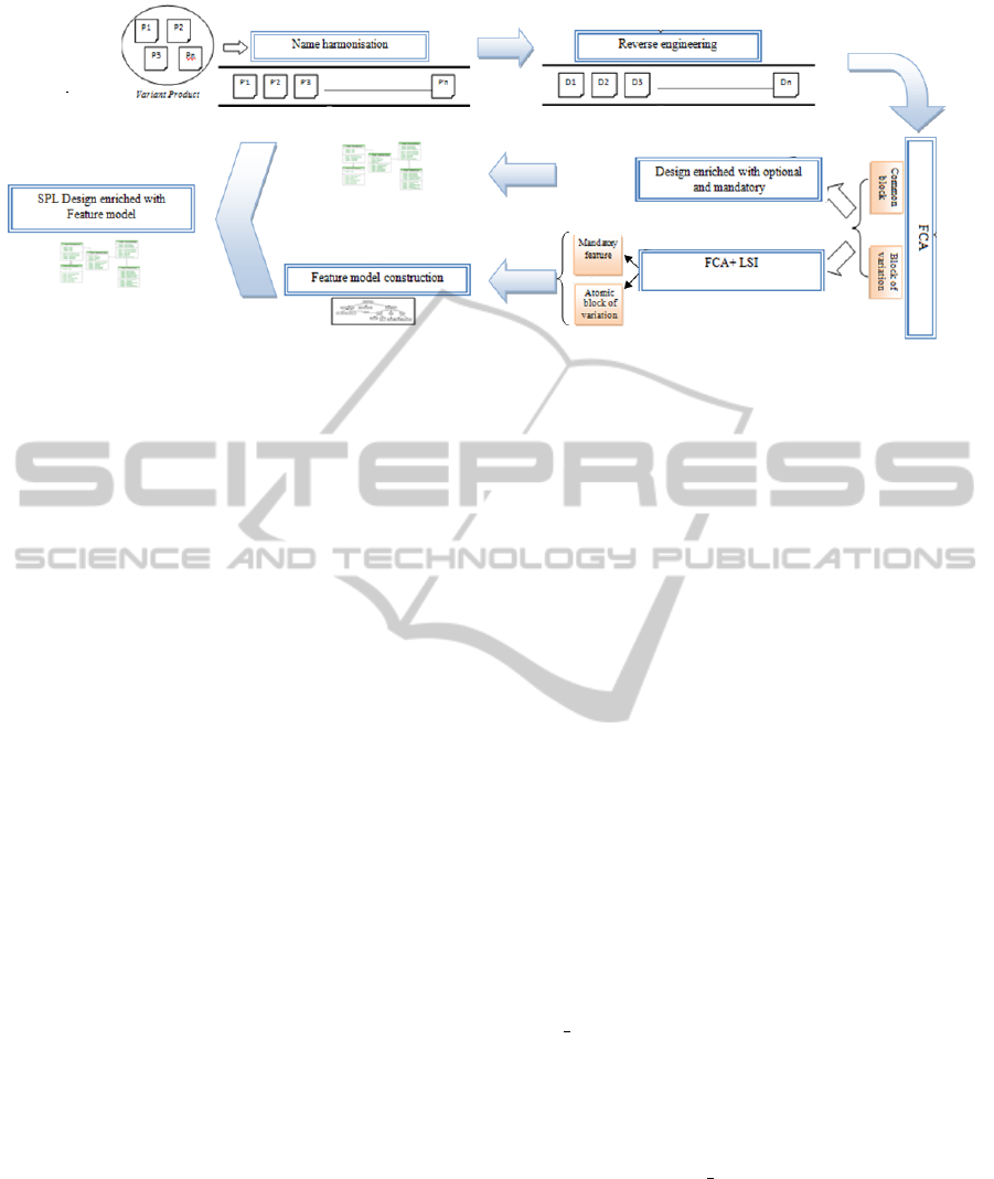
Figure 1: A bottom-up process to extract SPL design enriched with SPL-UML.
the relationships among a particular set of data ele-
ments. In our approach, the data represent the prod-
uct variants being analyzed; the data description is
represented through a table where the product vari-
ants constitute the rows while source code elements
(packages, classes, methods, attributes) constitute the
columns of the table.
From the table, a concept lattice is derived. The
concept lattice permits, in the first time, to define
commonalities and variations among all products.
The top element of the lattice indicates that certain
objects have elements in common (i.e., common ele-
ments), while the bottom element of the lattice show
that certain attributes fit common objects (variations).
Common blocks and blocks variation are composed
of atomic blocks of variation representing only one
feature.
Besides the blocks, the lattice also indicates the re-
lationships among elements. The following relation-
ships (Mandatory, Optional, Xor, Require and AND)
can be automatically derived from the sparse repre-
sentation of the lattice and presented to the analyst.
In our work, we suppose that the product vari-
ants are implemented by different developers. Con-
sequently, the products may have different structures.
For example, a class in one product can be replaced
in a second product with two classes where the at-
tributes and methods of the original class are dis-
tributed. Moreover, since all the products belong to
the same application domain, there are semantic re-
lationships among the words used in the names. To
define the similarity, we apply LSI. It allows to mea-
sure the similarity degree between names for pack-
ages, classes, methods and attributes. Informally, LSI
assumes that words that always appear together are
related (Binkley and Lawrie, 2011). Consequently,
we use LSI and FCA to identify features based on
the textual similarity. Similarity between lines is de-
scribed by a similarity matrix where the columns and
rows represent lines vectors. LSI uses each line in
the block of variations as a query to retrieve all lines
similar to it, according to a cosine similarity. We use
in our work the threshold for cosine similarity that
equals 0.70 (Binkley and Lawrie, 2011). The result of
LSI used as input for the FCA to group the similar el-
ements based on the lexical similarity. Thus, any doc-
ument that hasn’t a similar element will be ignored.
This process permits to identify atomics blocks of
variations (Feature).
The next step in our process determines the hierar-
chy and constraints among features and finalizes the
feature model construction. This phase has a three-
fold motivation. First, the features which are com-
posed of many elements (package, classes, attributes,
methods) are renamed based on the frequency of the
names of its elements. In addition, the organization
and structure of the features is also retrieved based on
the semantic criteria. In fact, to retrieve the organiza-
tion of the features, we use the semantic criterion:
• Hypernyms(FeatureN1, FeatureN2) − − −− >
FeatureN1 is the parent of FeatureN2
• Str extention(FeatureN1, FeatureN2) −− > Fea-
tureN1 OR FeatureN2
• Synonyms(FeatureN1, FeatureN2) − − −− >
FeatureN1 XOR FeatureN2
In fact, Hypernyms allow to construct the hierarchy of
feature models and Str extention and Synonyms per-
mit to determine constraints.
Finally, the constraints between the different fea-
tures that are extracted with FCA and LSI are verified
and some others are added based on the semantic cri-
teria.
At the end of this last step, all the features would
be collected in a feature model to specify the varia-
tions between the source products.
ABottomUpSPLDesignMethod
313
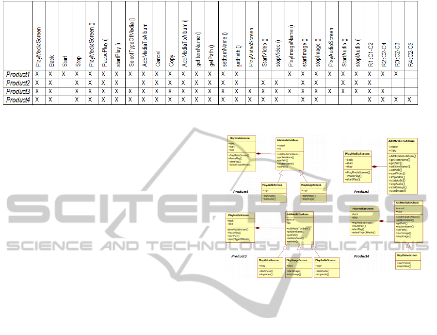
Figure 2: Part of the formal context describing mobile systems by class diagram elements.
4.4 Design Elements Extraction
and SPL Design Extraction
In order to tolerate differences among the design of
the product variants, we adapt the original FCA tech-
nique (Binkley and Lawrie, 2011): here, the FCA is
applied to extract the common elements and the vari-
able elements of the design. The data description is
represented through a table where the product vari-
ants constitute the rows while class’ diagram elements
(packages, classes, methods, attributes) and relation-
ship between classes constitute the columns of the ta-
ble.
Afterward, a concept lattice is derived.The top el-
ement of the lattice indicates the common elements
while the bottom element of the lattice show vari-
ations of certain attributes. This process permits
us, first, to derive design enriched with optional and
mandatory.
The organization and structure of the SPL design
is retrieved based on the following construct rules:
• R1: Each mandatory class will be presented with
her mandatory elements (attribute, method).
• R2: If a relationship is mandatory, then the asso-
ciation ends are mandatory and it will be present
in the design.
• R3: If a relationship has a startAssociation or
an endAssociation mandatory, will be present in
the design and the optional startAssociation or en-
dAssociation will be present and stereotyped ”rec-
ommended”.
• R4: The rest of the optional element will be
present in the design according to the degree of
its presence in all the class’ diagrams.
Finally, we propose to represent the design of the
SPL using our UML profile enriched with the infor-
mation extracted from the feature model generated.
Figure 3: Class diagrams of four product variants.
5 CASE STUDY
Our mobile phone SPL example is a software prod-
uct family with nine product variants. Our approach
takes as input the source code of a set of product vari-
ants in this application domain. To extract the class
diagram, we reverse engineered the code and con-
structed a class diagram as discussed in section 4.2.
The class diagram of products after reverse engineer-
ing is shown in figure 3.
In order to tolerate some differences among the
class’ diagram, we apply the FCA to analyze elements
of class diagrams. The data description is represented
through a table where the product variants constitute
the rows, while the classes diagrams elements (pack-
ages, classes, methods, attributes) and relationship
between classes constitute the columns of the table.
After that, a concept lattice is derived (see figure 4).
This latter defines the commonalities and the varia-
tions among all products. Due to space limitations,
we apply FCA on four products (see figure 2).
The top elements of the lattice indicate that some
objects have features in common. These latter are
mandatory in the class diagram, however, the others
are optional. Applying FCA, LSI and semantic crite-
ria, all the features are collected in a feature model to
MODELSWARD2014-InternationalConferenceonModel-DrivenEngineeringandSoftwareDevelopment
314
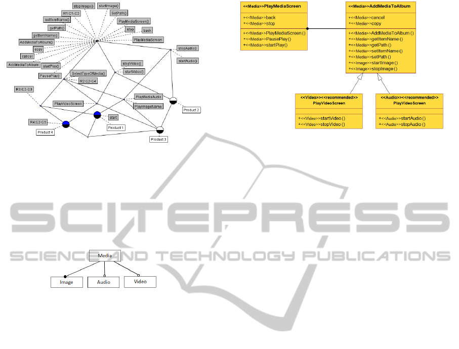
Figure 4: The lattice for the formal context.
specify the variations between these products (Maa-
zoun et al., 2013). The feature model of the mobile
system is shown in Figure 5; the features with white
circles are Optional while the features with black cir-
cles are Mandatory.
Figure 5: Feature Model result.
In the second step, we perform the SPL design
construction. In fact, all mandatory classes will be
present with their mandatory methods and attributes.
In the mobile phone example, the class ”PlayMedi-
aScreen” and its attributes ”back” and ”stop” and
methods ”PlayMediaScreen()”,”PausePlay”, ”start-
Play” are mandatory. Then, all mandatory relation-
ship will be presented like ”R1:C1-C2” (see figure 2).
Every relationship having an associationEnd manda-
tory will be presented like ”R2:C2-C4” and ”R3:C2-
C3”.
Finally, the class diagram corresponding to the
SPL is derived. This diagram is enriched by infor-
mation extracted from the feature model illustrated in
figure 5. As illustrated in figure 6, the classes have
different stereotypes. For example, AddMediToAl-
bum belongs to the feature Media while startImage
belongs to the feature Image.
6 CONCLUSIONS
In this paper, we first reviewed existing works for
feature model extraction from product variants and
presented existing UML profiles for SPL. Secondly,
we presented a new method deriving an SPL design
enriched with information extracted from the feature
Figure 6: The class diagram of the SPL represented with
SPL-UML.
model. Besides accounting for naming differences,
our method has the advantage of identifying automat-
ically feature model and design in source codes with
different structures. In addition, it models the SPL de-
sign in a new UML profile (SPL-UML) that enriches
the UML diagrams with feature model information.
The feasibility of the proposed approach is illustrated
through the extraction of the feature model and design
of an SPL for mobile phones. In our future works,
we are examining how to take advantage of the SPL-
UML notation to propose a maintenance process for
SPL.
REFERENCES
Al-Msie’Deen, R., Seriai, A., Huchard, M., Urtado, C.,
Vauttier, S., and Salman, H. (2012). An approach
to recover feature models from object-oriented source
code. In Day Product Line 2012.
Binkley, D. and Lawrie, D. (2011). Information retrieval
applications in software maintenance and evolution.
In Encyclopedia of Software Engineering, pages 454–
43.
ClauB, M. (2005). Modeling variability with uml. s.l. Dres-
den University of Technology.
Clements, P. and Northrop, L. (2001). Software product
lines: Practices and patterns. SEI Series in Software
Engineering.
Czarnecki, K. and Eisenecker, U. (2000). Genera-
tive programming - methods, tools and applications.
Addison-Wesley.
Ganter, B. and Wille, R. (1996). Formal concept analysis:
Mathematical foundations. Springer-Verlag.
Gomaa, H. (2005). . designing software product lines with
uml. Software Engineering Workshop Tutorial.
Kang, K., Cohen, S., Hess, J., Novak, W., and Peterson, A.
(1990). Feature-oriented domain analysis (foda) fea-
sibility study,. Technical report CMU/SEI-90-TR-21,
Software Engineering Institute,Carnegie Mellon Uni-
versity,.
ABottomUpSPLDesignMethod
315

Maazoun, J., Bouassida, N., and Ben-Abdallah, H. ((July
2013)). Feature model extraction from product source
codes based on the semantic aspect. ICSOFT13.
Nan, N. and Steve, E. (2009). Concept analysis for prod-
uct line requirements. In Proceedings of the 8th ACM
international conference on Aspect-oriented software
development, AOSD ’09, pages Pages 137–148, New
York, NY, USA.
Riebisch, P. (2003). Using feature modeling for program
comprehension and software architecture recovery.
Huntsville Alabama, USA.
Salman, H., Seriai, A., Dony, C., and Al-Msie’Deen, R.
(2012). Genetic algorithms as recovering traceability
links method between feature models and source code
of product variants. In Day Product Line 2012.
She, S., Lotufo, R., Berger, T., Wesowski, A., and Czar-
necki, K. (2011). Reverse engineering feature models.
pages 461–470.
Ziadi, T. (Dcembre, 2004). Manipulation de lignes de pro-
duits en uml. Thse de doctorat, Universit de Rennes
1.
Ziadi, T., Frias, L., da Silva, M. A. A., and Ziane, M. (2012).
Feature identification from the source code of product
variants. pages 417–422.
Ziadi, T. and Jezequel, J. (2005). Designing software prod-
uct lines with uml. Software Engineering Workshop
Tutorial.
MODELSWARD2014-InternationalConferenceonModel-DrivenEngineeringandSoftwareDevelopment
316
