
WIRELESS POWER TRANSMISSION IN URSI
Naoki Shinohara
1
1
Research Institute for Sustainable Humanosphere, Kyoto University, Gokasho, Uji, Kyoto, Japan
shino@rish.kyoto-u.ac.jp
Keywords: Wireless Power Transmission, Energy Harvesting, Rectenna, Beam Forming, Phase Array
Abstract: In URSI, Inter-Commission Working Group on Solar Power Satellites (SPS) was established in 2002 and
the URSI Board has been working on writing and reviewing an URSI White Paper on SPS, which was
published on June 2007, because the SPS is one of huge application of radio science. One of important
application of the radio science on the SPS is a wireless power transmission (WPT) via microwave
(microwave power transmission ; MPT). At first, the WPT walked along with the SPS. But now we have
some kinds of the WPT and its commercial applications. One of important application of the WPT is an
energy harvesting. The other is MPT for the SPS. Some important researches are done as URSI activities in
Japan. It is high efficiency rectenna development at low power and at wide band frequency. It is also high
efficiency and low cost phased array for the MPT and the SPS. Some of them were published in URSI
conference. In this paper, I will show mainly present status of the WPT in Japan and in the world and will
also show a relationship between the WPT and the URSI activities.
1 INTRODUCTION
In URSI, Inter-Commission Working Group on
Solar Power Satellites (SPS) was established in 2002
and the URSI Board has been working on writing
and reviewing an URSI White Paper on SPS because
the SPS is one of huge application of radio science.
The White Paper on SPS was published on June,
2007(SPS White Paper, 2013). One of important
application of the radio science on the SPS is a
wireless power transmission (WPT) via microwave
(microwave power transmission ; MPT). The MPT
researches walked along the SPS researches from the
end of 1960s(Brown, 1984)(Matsumoto, 2002). The
SPS was one and only application of the MPT
because the commercial or industrial MPT system,
especially antennas, theoretically become larger than
that imagined by users. But in 21
st
century, some
new WPT systems arise to be applied for the
commercial or industrial uses(Shinohara, 2011). One
is called a resonance coupling WPT which was
established by MIT’s group in 2006. The other is
called an energy harvesting which includes
rectifying technologies from weak broadcasting
radio waves and power generations from vibration,
heat, and light, etc. Technologies for the energy
harvesting from radio waves and for the MPT are the
same. Difference is only that the energy harvesting
is a passive system only with a rectenna, rectifying
antenna, against that the WPT is an active system
with a power transmitter (Fig.1). The energy
harvesting is supported by low power device
technologies and is applied for ubiquitous sensor
network or simple wireless communications. On
contrary, we can transmit power and information
simultaneously on the WPT system. The URSI can
support to make new theory of the MPT including
the energy harvesting and the SPS and can advance
its commercialization. In this paper, I will show
mainly present status of the WPT in Japan and in the
world and will also show a relationship between the
WPT and the URSI activities.
49
Shinohara N.
WIRELESS POWER TRANSMISSION IN URSI.
DOI: 10.5220/0004785100490053
In Proceedings of the Second International Conference on Telecommunications and Remote Sensing (ICTRS 2013), pages 49-53
ISBN: 978-989-8565-57-0
Copyright
c
2013 by SCITEPRESS – Science and Technology Publications, Lda. All rights reserved
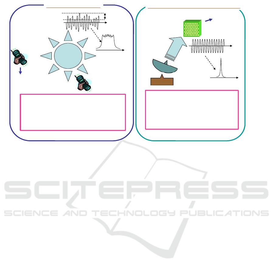
Energy Harvesting
Transmitter
・We need only a part of transmitted
power (which is wasted as wireless
communications)
・Wide band because we transmit an
information
Transmitter
Transmitted
Power
Receiver
→Power
・We need almost all transmitted
power
・Very narrow band because we use
carrier (pure)
・Simultaneous transmission of power
and information is available.
.Conversion efficiency is important.
Receiver
→Power
Only Carrier for WPT
Time and Space
Information
Frequency
Very Narrow
Wide
Electric Power
to User
Electric Power
to User
Receiver
→Power
Transmitted
Power
Transmitted
Power
Transmitted
Power
Frequency
Time and
Space
Transmission efficiency is important.
Microwave Power Transmission
Figure 1 Microwave Power Transmission and Energy Harvesting
2 ENERGY HARVESTING
An energy harvesting is most hopeful wireless
power application recently because there have been
no allowed frequency for a wireless power
transmission in the world. The energy harvesting
does not require special frequency because the
system is passive and the wireless power is
harvested from broadcasting radio waves or waves
of wireless communications. There are a lot of
researches and developments of the energy
harvesting systems in the world(Sample,
2009)(Collado, 2012)(Visser, 2013)(Popovic, 2013).
Some of them are researches based on RF-ID
technologies and some of them are that based on the
energy harvesting from the other power source like
vibration or solar.
In Japan, there are also some trials of the energy
harvesting from broadcasting waves. One is carried
out by ATR (Advanced Telecommunications
Research Institute International). They evaluated an
energy harvesting system from an 800 MHz cellular
BS. For this system, they developed an 800 MHz
band twin-loop antenna and an RF-DC conversion
circuit. The antenna gain of 5.2 dBi and the RF-DC
conversion efficiency of 9 % at -20 dBm input
power were obtained. Experimental results showed
that a 1.0 F electric double layer capacitor was
charged up to 469 mV in 19 hours and drove a low
power LCD thermometer for 10 minutes using its
stored energy(Kitazawa, 2013).
The other group is Univ. of Tokyo. They
developed an energy harvesting system from UHF
(at 550MHz) broadcasting wave. They chose charge
pump rectifying circuit to charge the tank capacitor
to 1.8 and 3.0V are 38 and 70 micro-watts
respectively at 550 MHz. At a distance of 6.5km
from Tokyo TV tower, the energy harvesting circuit
charges up the 100uF charge tank to 2.9V in
3minutes making such a device ideal for battery less
operation of wireless sensors for remote
monitoring/sensing in most urban areas using just
the existing terrestrial TV broadcast infrastructure
for power(Vyas, 2012).
Kyoto University’s group focuses on development
of high efficiency rectenna at low power and at wide
band frequency. First of all, we, Kyoto University’s
group, developed high efficiency rectenna at 5.8GHz
with pure spectrum in a MPT system. We proposed
a concept of ‘Ubiquitous Power Source (UPS)’ with
the MPT technologies(Shinohara, 2005). In the UPS
system, we transmit a microwave power whose
microwave is not modulated and pure spectrum and
whose power is limited below 1mW/cm
2
, safety
regulation for human. We chose frequency of
2.45GHz or 5.8 GHz which are on ISM (Industrial,
Science, and Medical) band. We developed high
efficiency rectenna at low power with expectation of
Second International Conference on Telecommunications and Remote Sensing
50
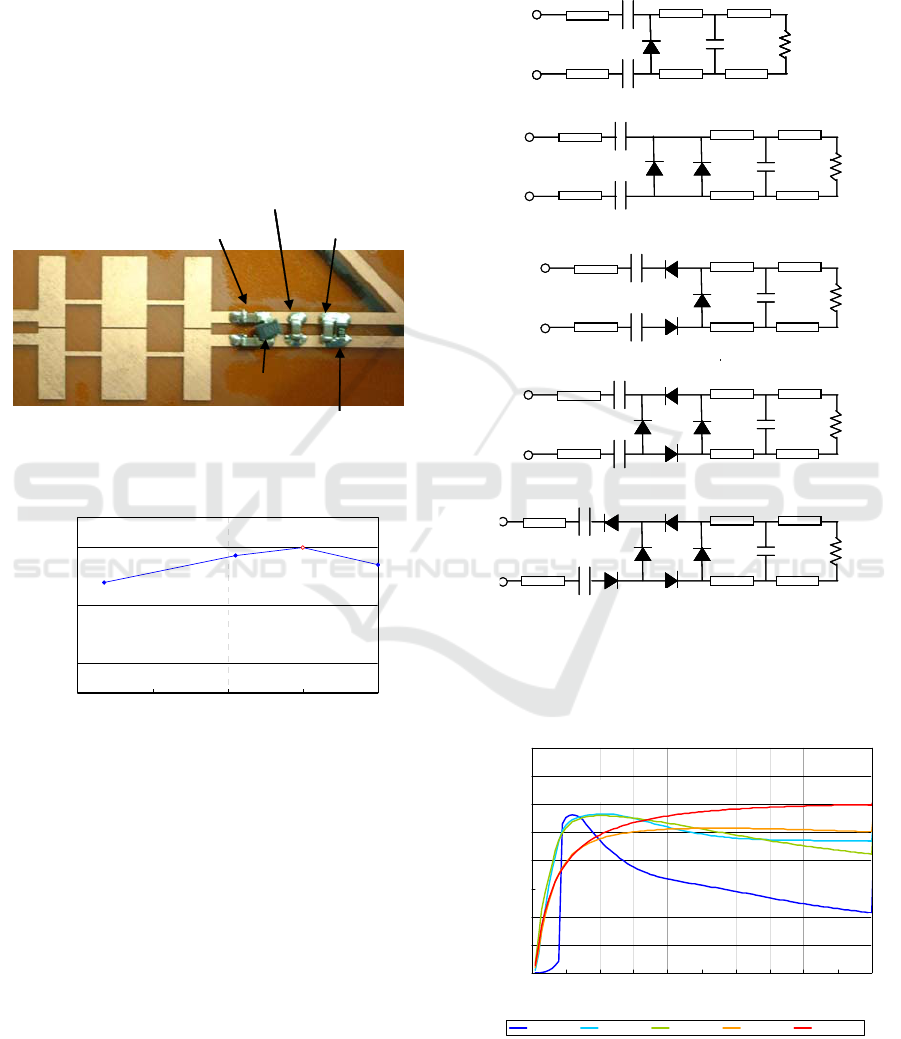
application for the UPS and the energy harvesting. A
picture of the developed rectifying circuit of the
rectenna is shown in Fig.2. Target frequency is
5.8GHz continuous wave (CW). The circuit is based
on shingle shunt full wave rectifier whose theoretical
RF-DC conversion efficiency is 100% with one
diode only. As a rectifying theory, line length
between a diode and a capacitance (C2) must be λ/4
for 100% efficiency. However, we change the line
length between a diode and a capacitance to increase
the RF-DC conversion efficiency at 1mW. As a
result, we achieved approximately 50% of the RF-
DC conversion efficiency at 1mW, 1kΩ in 5.8GHz
CW(Fig.3).
LPF
DC cut capacitance
Diode
(HSMS285B)
C2
:
capacitance for output filter 1
load
C3:capacitance
for output filter 2
<Rectifying Circuit>
LPF
DC cut capacitance
Diode
(HSMS285B)
C2
:
capacitance for output filter 1
load
C3:capacitance
for output filter 2
<Rectifying Circuit>
Figure 2 Developed Rectenna for Rectifying of Low
Power
0
10
20
30
40
50
60
400 600 800 1000 1200
負荷抵抗
[
Ω
]
RF- DC変換効率
[
%
]
Connected Load (Ω )
RF-DC Conversion Efficiency (%) (Exp.)
Figure-3: Experimental Result of Load
Characteristics of RF-DC Conversion Efficiency at
1mW input microwave power (without Low-Pass
Filter)
For 2.45GHz system, we chose the other approach
to increase the RF-DC conversion efficiency of the
rectenna. Optimization of the line length between a
diode and a capacitance was the same. However, we
could not increase the efficiency enough with one
diode only. Therefore, we increased a number of the
diodes and put them like a charge pump rectifier
without capacitances (Fig.4). As circuit simulations,
we achieved 55.3% at 0.1mW, 8.2kΩ in
2.45GHzCW with type of 6EA (Fig.5). All
distributed lines and capacitances are optimized and
different in each circuit. Optimum connected loads
are also different in each circuit. This was
collaborative research with Kyoto University and
Mitsubishi Electric Corporation.
RL
SBD:2コ
E1
E1 E2
E2 E3
E3
C2
C1
C1
SBD
SBD
RL
E1
E1 E2
E2 E3
E3
C2
C1
C1
SBD
SBD
RL
m
m
E1
E1 E2
E2 E3
E3
C2
C1
C1
SBD
SBD
SBD:3コ
RL
SBD
E1
E1 E2
E2 E3
E3
C2
C1
C1
SBD
SBD
SBD:3コ
RL
SBD
m
E1
E1 E2
E2 E3
E3
C2
C1
C1
SBD
RL
E1
E1 E2
E2 E3
E3
C2
C1
C1
SBD
E1
E1 E2
E2 E3
E3
C2
C1
C1
SBD
RL
SBD:1コ
m
SBD:4コ
RL
E1
E1 E2
E2 E3
E3
C2
C1
C1
SBD
SBD
RL
SBD
SBD RL
E1
E1 E2
E2 E3
E3
C2
C1
C1
SBD
SBD
RL
SBD
SBD
m
m
SBD:6コ
SBD
RL
E1
E1 E2
E2 E3
E3
C2
C1
C1
SBD
SBD
RL
SBD
SBD
SBD
SBD
RL
E1
E1 E2
E2 E3
E3
C2
C1
C1
SBD
SBD
RL
SBD
SBD
SBD
1EA
2EA
3EA
4EA
6EA
Figure-4 Proposed Rectifying Circuits in
2.45GHzCW (E : Distributed Line, C : Capacitance,
SDB : Shottky Barrier Diode)
0
10
20
30
40
50
60
70
80
0.0 0.1 0.2 0.3 0.4 0.5 0.6 0.7 0.8 0.9 1.0
In
p
ut Power
[
mW
]
η
[
%
]
Di
ode
6
EA Di
ode
4EA Di
ode
3
EA Di
ode
2EA Di
ode
1EA
▼
55.3%
3EA
2EA
1EA
4EA
6EA
with 8.2kΩ 3.9kΩ 3.9kΩ 1.8kΩ 1.8kΩ
Figure 5 Simulation Results of Proposed Rectifying
Circuits in 2.45GHzCW
Wireless Power Transmission in URSI
51
RF-DC conversion efficiency of these rectennas at
low input power is high. However, these are only for
continuous waves. We have to develop a rectenna
for modulated radio waves whose frequency range is
wide. Theoretically, it is difficult to increase RF-DC
conversion efficiency by modulated radio waves
because some high Q circuits like distributed lines
are used to increase the efficiency in a single shunt
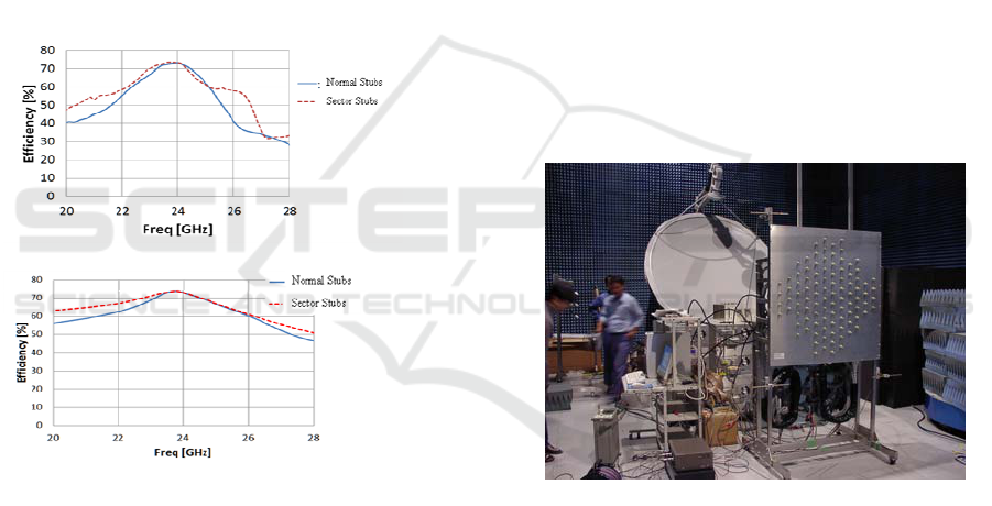
rectifier. For an energy harvesting with high
efficiency, we, Kyoto University and NTT, proposed
new rectifying circuit based on the single shunt
rectifier in 2013(Shinohara and Hatano, 2013). It is
in 24GHz band. The experimental result is shown in
Fig.6. We put sector-type open stubs as resonators at
higher harmonics instead of a capacitance in a single
shunt rectifier. Compared with normal stubs as
resonators at higher harmonics, the frequency range
is expanded.
(a)
(b)
Figure 6 Simulation Result of RF-DC Conversion
Efficiency of Class-F Load Rectenna with Sector
Stubs(a) with Impedance Matching at 24GHz (b)
with Impedance Matching at All Frequencies
(Shinohara, 2013)
3 MICROWAVE POWER
TRANSMISSION
In URSI activities, we mainly focused on a MPT and
a SPS as a MPT application in Japan. Especially,
high efficiency beam forming in the MPT and the
SPS system is important work. It is not only a new
beam forming theoretical algorism but also a beam
forming algorism with considering a phased array
system.
For the SPS, phased arrays for the MPT were
historically developed (Shinohara, 2013). Magnetron
phased array developed in Kyoto University is one
of hopeful phased array for the SPS. We developed
phase controlled magnetron for the SPS. However,
one magnetron generates high microwave power, for
example, 1kW. For the SPS, the high output power
is a weak point because an output power from 1
antenna in the SPS will be less than 1 W. We have to
coexistent both beam forming without grating lobes
and high efficiency array. In order to coexistent both,
we consider two systems. One is a phased array with
power divider and sub-phase shifters whose loss are
small, between antennas and a magnetron
(Shinohara, 2002). We showed that we could keep
high beam collection efficiency at wider beam
scanning with magnetron phased array with sub-
phase shifter, comparing the simple magnetron
phased array. Based on the result, we developed
magnetron phased array with sub-phase shifters in
Kyoto University (Fig.7). The research results were
referred in URSI White paper on SPS.
Figure 7 Magnetron Phased Array with Phase
Controlled Magnetron through 1-bit sub-phase shifters
after 8-way power dividers
The other approach to coexistent both beam
forming without grating lobes and high efficiency
array, we proposed new random array to suppress
grating lobes and to increase beam collection
efficiency simultaneously (Shinohara, 2008)
(Shishkov, 2009)(Shishkov, 2011). In conventional
random array, we can suppress grating lobes with
large antenna spacing like a magnetron array.
However, energy of the grating lobes merges not to
main lobe but to side lobes. As a result, beam
collection efficiency of large spacing array with
grating lobes and random array without grating lobes
Second International Conference on Telecommunications and Remote Sensing
52
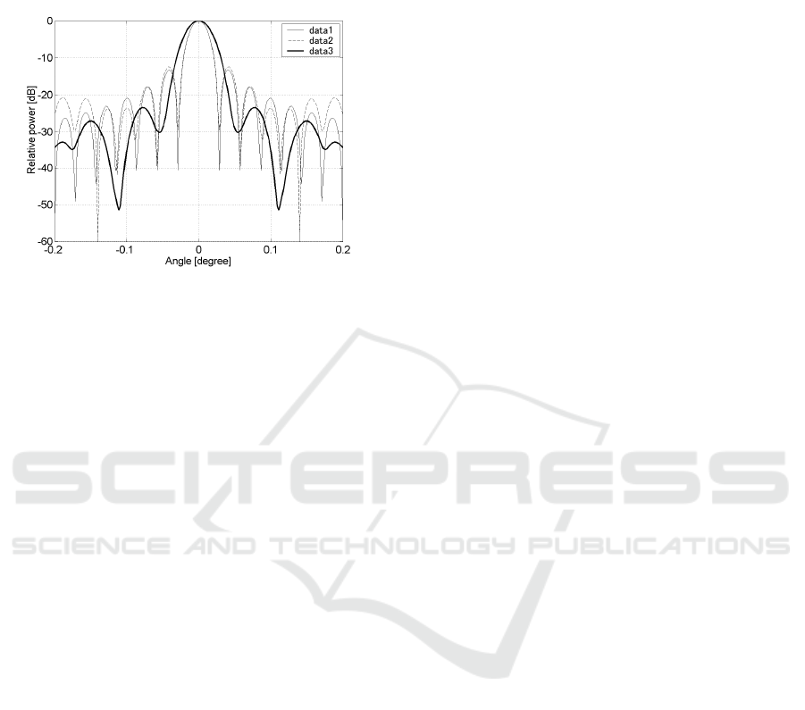
are the same and low. With our new proposed
element spacing algorism, grating lobes are
suppressed and beam collection efficiency is
increased simultaneously (Fig.8).
Figure 8 Beam Patterns of data3 (Proposed New
Positioning Algorism) and data2 (Conventional
Random Array), data1 (Uniform Array) for 1000
elements, average spacing
λ
2=
av
d
and uniform
excitation (Shinohara, 2008)
4 CONCLUSIONS
Radio waves can carry not only information but also
energy. A wireless power transmission is one of
important new radio scientific and technical region
in URSI. In this paper, I only show technical results
of the WPT and an energy harvesting. However,
propagation, plasma physics, EMC and biomedical
of the radio wave are also very important matters to
realize commercial WPT and the SPS. I hope fruitful
discussions will be in URSI.
REFERENCES
Brown, W. C., 1984. The history of power transmission by
radio waves, IEEE Trans. Microwave Theory and
Techniques, MTT-32, No.9, pp.1230-1242
Collado, A., and A. Georgiadis, 2012. Improving Wireless
Power Transmission Efficiency Using Chaotic
Waveforms, Proc. of IMS2012, TU4F-1, 1849-
LL5P2GLnBqBm-2.pdf
Kitazawa, S., M. Hanazawa, S. Ano, H. Kamoda, H. Ban
and K. Kobayashi, 2013. Field Test Results of RF
Energy Harvesting from Cellular Base Station, Proc.
of GSMM2013, 1569736061.pdf
Matsumoto, H., Dec. 2002. Research on Solar Power
Station and Microwave Power Transmission in Japan:
Review and Perspectives, IEEE Microwave Magazine,
pp.36-45
Popovic, Z., E. Falkenstein, and R. Zane, 2013.
Low-
Power Density Wireless Powering for Battery-less
Sensors,
Proc. of RWS2013, MO3A, pp.31-33
Sample, A. P. and J.R. Smith, 2009. Experimental Results
with two Wireless Power Transfer Systems, Proc. of
RWS2009, MO2A-5, pp.16-18
Shinohara, N., H. Matsumoto, and K. Hashimoto, 2002.
“Solar Power Station/Satellite (SPS) with Phase
Controlled Magnetrons”, Proc. of 2002 Asia-Pasific
Microwave Conference (APMC), pp.2-795-798
Shinohara, N., T. Mitani, and H. Matsumoto, 2005. Study
on Ubiquitous Power Source with Microwave Power
Transmission, Proc. of URSI General Assembly 2005,
C07.5(01145).pdf
Shinohara, N., B. Shishkov, H. Matsumoto, K.Hashimoto,
and A.K.M. Baki, 2008. New Stochastic Algorithm for
Optimization of Both Side Lobes and Grating Lobes in
Large Antenna Arrays for MPT, IEICE Trans.
Communications, Vol.E91-B, No.1, pp.286-296
Shinohara, N., 2011, Power without Wires, IEEE
Microwave Magazine, Vol.12, No.7, pp.S64-S73
Shinohara, N., K. Hatano, T. Seki, and M. Kawashima,
2013. Development of Broadband Rectenna at
24GHz”, Proc. of GSMM2013, 1569734001.pdf
Shinohara, N., 2013. Beam Control Technologies With a
High-Efficiency Phased Array for Microwave Power
Transmission in Japan, Proceeding of IEEE,
10.1109/JPROC.2013.2253062, 0020-SIP-2012-
PIEEE
Shishkov, B., K. Hashimoto, H. Matsumoto, N. Shinohara
and T. Mitani, 2009. Direction Finding Estimators of
Cyclostationary Signals in Array Processing for
Microwave Power Transmission, Pliska Stud. Math.
Bulgar., Vol.19, pp.245-268
Shishkov, B., N. Shinohara, H. Matsumoto, K. Hashimoto,
and T. Mitani, 2011. On the Minimization of Side-
Lobes in Large Antenna, Proc. of URSI General
Assembly 2011, CD-ROM CHGBDJK-5.pdf
SPS White Paper, http://www.rish.kyoto-u.ac.jp/
SPS/index.html, 2013
Visser, H. J., 2013. Printed Folded Dipole Antenna
Design for Rectenna and RFID Applications, Proc. of
EuCAP2013, pp.2766-2769
Vyas, R. J., H. Nishimoto, M. Tentzeris, Y. Kawahara, T.
Asami, 2012. A Battery-Less, Energy Harvesting
Device for Long Range Scavenging of Wireless Power
from Terrestrial TV Broadcasts, Proc. of IMS2012,
TU4F-2, 2060-LL6Ai1QvYbBc-2.pdf
Yamamoto, A., H. Okegawa, N. Shinohara, and H.
Matsumoto, 2006, Development of High Efficiency
Thin Film Rectenna for Low-Power Input, Prof. of the
3rd International Symposium on Sustainable Energy
System, p.219
Wireless Power Transmission in URSI
53
