
Collision Energy Mitigation through Active Control of Future
Lightweight Vehicle Architectures
James E. Trollope and Keith J. Burnham
Control Theory and Applications Centre, Faculty of Engineering and Computing,
Coventry University, Coventry, CV1 5FB, U.K.
Keywords: Active Control, Automotive Industry, Collision Mitigation, Lightweight Vehicles, Smart Materials
and Structures.
Abstract: The paper challenges the current state-of-the-art which is accepted by the automotive industry. Present day
vehicles are unsophisticatedly over-engineered and, as a consequence, are uneconomic, hence unsustainable.
Vehicles currently under development, however, offer tremendous opportunities for shifting from this
position to include onboard active safety systems, e.g. collision avoidance. It is argued that future vehicles
should be significantly lighter and exploit the developing safety features to the full. Indeed, such a
development would reduce the existing need for crashworthiness. The above arguments coupled with
parallel developments in smart materials, paves the way towards a new generation of actively controlled
vehicle architecture design. Whilst the move to lighter vehicles, with onboard active safety systems and
actively controlled structures, may be seen as controversial, there is a convincing case for a paradigm shift
towards a truly sustainable transport future.
1 INTRODUCTION
A mechanical structure is an assembly that serves an
engineering function, examples being bridges,
vehicles and ships. For an automotive vehicle, the
major component of the structure is the architecture.
When designing the architecture, optimisation of key
components of the structure is performed, such as
the profile, configuration, size, cross section and
material in order to achieve a desired performance
(Hunkeler et al., 2013). With the ever-increasing
need to reduce CO
2
emissions, hence fuel and
energy consumption, the mass of the vehicle
structure, which accounts for approximately one
quarter of the total vehicle mass, needs to be
reduced. Evidence from ongoing research and
development programmes has shown that reducing
the mass of the architecture is by far the most
effective approach for achieving reduced energy
consumption (Lotus, 2010). On the contrary, there is
a current need to satisfy crashworthiness criteria,
with the structure being designed to passively soften
on impact in a predetermined manner. As a result,
vehicle architectures have in fact increased in mass,
with an average increase of 8kg for passenger
vehicles per year from 1980 to 2006 (Ellis, 2011).
To challenge this, the UK government has set a
target to achieve 60% reduction in CO
2
emissions by
2030 (Hickman and Bannister, 2006). For this target
to be met, current trends in the vehicle design need
to be reversed by introducing radically new
innovative ideas for future vehicles.
Various strategies are currently being deployed
to achieve reduced emissions, namely developments
with materials and the introduction of optimised
hybrid and electric drive trains.
Traditionally, steel has been extensively used for
vehicle architectures, however, recent years has
witnessed a change, with companies, such as Jaguar
Land Rover, now manufacturing certain vehicle
models from aluminium. The future of lightweight
vehicle architecture design is anticipated to be either
carbon fibre reinforced plastics or a mixture of
materials. However, due to the high production
costs, concerns over recyclability and time
consuming processes, there is currently some
uncertainty over the future use of composites
(Ghassemieh, 2011). This leads naturally to the
alternative possibility of employing a mixed material
vehicle architecture. This involves selecting the most
suitable material for a given purpose, with materials
such as, aluminium, steel and magnesium being
477
E. Trollope J. and J. Burnham K..
Collision Energy Mitigation through Active Control of Future Lightweight Vehicle Architectures.
DOI: 10.5220/0004598304770484
In Proceedings of the 10th International Conference on Informatics in Control, Automation and Robotics (ICINCO-2013), pages 477-484
ISBN: 978-989-8565-71-6
Copyright
c
2013 SCITEPRESS (Science and Technology Publications, Lda.)

employed (Berger et al., 2009).
The development of optimised drive trains for
electric and hybrid vehicles is also taking place.
However, there are a number of outstanding issues
to be overcome, such as, limited range, lack of
charging ports, safety of fuel cells, high cost
involved with batteries and, with the additional drive
train components in these vehicles, an increase in
mass. These potential obstacles would appear to be
slowing the uptake of electric and hybrid electric
vehicles for the present-day average road user.
As mentioned earlier, one of the compelling
arguments against reducing mass is the current need
to comply with requirements of crashworthiness,
since this has evolved to become probably the most
important design aspect of a vehicle. Early attempts
to absorb energy in a controlled manner during a
collision have included hydraulic rams for the
longitudinal members of the vehicle architecture
(Jawad, 2003) and bumper dampers. Recently,
pyrotechnics have been used to actively control the
softening in the event of pedestrian impacts
(Thatcham, 2012).
The use of advanced driver assisted systems
(ADAS) on vehicles, such as autonomous
emergency braking, collision avoidance, collision
mitigating braking and electronic stability control,
which are now being fitted as standard on vehicles,
will ultimately reduce the dependence on, or even
override, the driver. Effectively, the onboard ADAS
and active safety systems in the future are expected
to reduce the number of collisions as well as the
velocities of such collisions. Significant
developments in the deployment of ADAS is
currently taking place, with car manufacturers, such
as Volvo, investing in active safety systems, with
their aim being to achieve zero fatalities or seriously
injured passengers in a Volvo by 2020 (Eugensson,
2009).
2 PROBLEM FORMULATION
In this section, current and future trends concerning
vehicle mass are presented, along with formulating
the problem for actively controlled structures.
2.1 Vehicles of Dissimilar Mass
The move towards lightweight vehicles will
inevitably involve even greater differences in masses
between vehicles, such as passenger vehicles, lorries
and trucks. A small vehicle can be of mass as little
as 800kg whereas a laden/unladen lorry could easily
be a factor 20/10 times heavier (or even more) i.e.
presenting problems to smaller vehicles. This can be
highlighted via an example, illustrating that the
future low mass vehicle is vulnerable compared to a
larger vehicle. Consider, for example, a collision
between a moving and stationary vehicle with
dissimilar masses, such that a larger vehicle initially
travelling at a velocity, given by
12m/s,
collides with a smaller stationary vehicle with a
velocity,
0. Denote the mass of the vehicles as
and
given by 1000kg and 500kg,
respectively. Denote the final velocity, i.e. after the
collision, as
. It is well known that the
conservation of momentum can be expressed as
, where
. It can be deduced that the final velocity of the
combined mass of the two vehicles is 8m/s.
From the principle of conservation of energy, the
kinetic energy before and after the collision must be
equal, consequently
∆,where ∆ is the collision energy
dissipated within the vehicle structures. It can be
deduced that ∆ for this particular collision is 24kJ.
It is known (Schmidt et al., 1998) that the ratio of
absorption of energy from a collision is proportional
to the change in the vehicle velocities, denoted ∆
and ∆
where ∆
and ∆
. It can also be deduced that the ratio
of∆
:∆
is the same as
:
, so that the smaller
of the two vehicles is always the more vulnerable.
The above example serves to highlight the need
for active control of automotive structures in order
to share the energy absorption where, should a small
vehicle collide with a larger vehicle, the larger
vehicle structure will soften to absorb the smaller
vehicle (with the smaller vehicle being allowed to
stiffen on impact). The objective of the approach is
to control the structural properties to ensure
optimum mitigating energy absorption in an actively
controlled manner.
2.2 Brief Review of Smart Materials
Rapid advances in the electronics industry have
taken place in recent years with on-board embedded
micro-processors and control systems being applied
in a wide range of applications, with the automotive
sector providing many examples, e.g. ADAS.
Developments have also taken place in the area of
smart materials, whereby electronic devices, e.g.
piezoelectric systems, are bonded to material to
produce enhanced structural properties. Whilst the
application of actively controlled structures have
ICINCO2013-10thInternationalConferenceonInformaticsinControl,AutomationandRobotics
478

been reported in the literature for aircraft, bridges,
buildings and spacecraft to enhance their structural
properties, there have been little or no published
reports in the automotive sector (Gabbert, 2002).
Smart materials have the ability of possessing
functions such as sensing, actuating and controlling.
These functions can be used in a structure where
there is a need to react under the influence of the
environment, i.e. an induced force (Gupta and
Srivastava, 2010).
An example of a smart material is a piezoelectric
device (formed by an alloy of lead (Pb), Zinc (Zn)
and Titanium (Ti)) which is often referred to as PZT.
When a mechanical stress is applied, the
piezoelectric effect produces a charge caused by the
motion of electric dipoles within the material,
known as the direct effect. This can be used for
energy harvesting. Piezoelectric materials also
exhibit a reciprocal effect, known as the converse
effect. When an electric field is applied the result is
a mechanical response, in this case a displacement.
Other examples include shape memory alloys, where
given an electric current input, i.e. heat, the shape of
the structure can be changed, thus, varying its
rigidity (Leo, 2007).
This brief introduction has demonstrated the
potential use of smart materials for changing the
properties of vehicle architectures.
2.3 Position Statement
Because vehicle architecture design is currently
driven by crashworthiness performance, it follows
that during normal every-day driving conditions the
vehicle structure is unsophisticatedly over-
engineered; with the architecture being significantly
different if crashworthiness requirements could be
met in a more efficient manner, i.e. actively
controlled, as outlined above.
It is at this juncture that the hub of the issue
becomes apparent. This issue, coupled with rapid
developments in active safety and in the deployment
of ADAS, forms a convincing premise for the
position statement. Thus, the position statement is as
follows: Due to effective onboard safety systems in
the future, collisions will be fewer and of lower
velocity, thus, markedly reducing the required levels
of crashworthiness. If this is the case, then future
vehicle structures will be lighter, thereby
exacerbating the dissimilar mass problem, outlined
in Section 2.1. Therefore, it is argued that vehicles
need to stiffen or soften, allowing the structural
properties to be actively controlled depending on the
collision being encountered. For example, if two
vehicles of different mass collide at the same
velocity, it would be expected that the lighter vehicle
would stiffen and the larger vehicle would soften in
order to optimally share the collision energy. Hence,
active control of smart structures is deployed to
mitigate the effects of these collisions in order to
control the energy absorption that is required for
each vehicle. It is conjectured in this position paper
that advances in smart materials, such as shape
memory alloys and piezoelectric materials coupled
with predictive and adaptive control, will lead to
research to provide a better solution to the collision
energy mitigation problem.
Following the argument through, future vehicles
equipped with ADAS and active control, will be
significantly lighter, hence, improving efficiency,
satisfying CO
2
legislation and at the same time,
maintaining or improving safety, whilst reducing the
current requirements for crashworthiness; rather
tending more towards a reduced aggressivity of the
vehicle fleet.
3 MODELLING STRUCTURES
FOR CONTROL
3.1 Preliminary Considerations
Each member or beam within a vehicle structure is
considered to be modelled as a mass, spring and
damper system. This is analogous with electrical
systems being modelled as combinations of
capacitance, inductance and resistance. In a
mechanical system, energy is stored in the mass and
spring elements and dissipated through damping.
There are basically two conceptual modelling
approaches when dealing with mechanical
structures, namely the nodal approach, where
displacements, velocities and accelerations at
specific points (or nodes) of a structure are of
interest, and the modal approach, where the spectral
properties, i.e. the eigenvalues, eigenvectors and
corresponding natural frequencies of the entire
structure are of interest. Whilst the use of the nodal
approach, leads to dependencies of nodes on each
other (i.e. coupled), use of the modal approach gives
rise to each mode being independent of each other
(i.e. uncoupled). As it will become clear, the design
of control algorithms for modal control is
considerably simpler than the control of a nodal
system, particularly when considering only a few
modes. As a consequence, attention will be given to
a particular form of the state-space modal model,
which is developed here for the design and
CollisionEnergyMitigationthroughActiveControlofFutureLightweightVehicleArchitectures
479

realisation of modal control algorithms.
It is assumed that the stiffness and dissipative
damping may be actively controlled in certain
members of the structure, hence changing the overall
structural properties. The simple interconnected two
member structure given in Figure 1 is considered for
the purpose of illustrating the modelling and control
approach.
The simple structure illustrated in Figure 1 has
two degrees of freedom denoted by the
displacements
and
, hence two structural
modes. As a starting point it is convenient to
consider a nodal model, which is subsequently
transformed to a modal model for both modelling
and control. In this regard it is convenient to assume
that when a vehicle, modelled as an interconnected
structure, is unconstrained, the spring stiffness and
damping factors at the extremities of the structure,
,
,
and
in Figure 1, are set to zero.
However, upon collision with an obstacle (or
another vehicle) it is assumed that, e.g.
and
,
become non-zero. In effect an unconstrained vehicle
may be considered as being in rigid body mode. In
constrained mode, i.e. when
and
become non-
zero, the vehicle then becomes a flexible structure.
Figure 1: Interconnected two-member system, where
,
denote the system masses,
,
,
denote the spring
stiffness coefficients and
,
,
denote the damping
coefficients.
3.2 Nodal Model
It is convenient to begin by considering a flexible
structure in the familiar nodal coordinates
represented by the following second order matrix
differential equation:
1
2
where the subscript denotes nodal representation.
Let
denote the number of degrees of freedom,
denote the number of outputs of interest and
denote the number of inputs. The quantities in (1)
and (2) are defined as:
is the
x 1
nodal displacement vector
is the
x 1 nodal velocity vector
is the
x 1
nodal acceleration vector
is the
x 1 input vector
is the
x 1 output vector
is the
x
nodal mass matrix
is the
x
nodal damping matrix
is the
x
nodal stiffness matrix
is the
x
nodal input matrix
is the
x
nodal output displacement matrix
is the x
nodal output velocity matrix
For convenience, let the masses
=
= 1, the
stiffness values
= 2
and
= 0 and let the
damping matrix be proportional to the stiffness
matrix, such that
= 0.01
. Consider the case of
a force input at mass 2, with outputs being
velocity of mass 2 and displacement and velocity of
mass 1. This yields the following matrices:
diag
,
) so that
.
The stiffness and
damping matrices are:
42
2 2
3
0.04 0.02
0.02 0.02
4
The input and output matrices are:
0
1
,
10
00
,
10
01
5
3.3 Modal Model
The modal coordinate presentation is obtained from
the nodal representation via a transformation. By
setting the damping matrix
in (1) to zero and
considering the unforced case (i.e.
= 0) the nodal
representation takes the form
0
6
Assume that the solutions are of the form
ϕ
where ϕ is a
x 1 vector so that
ϕ
and
ϕ
i.e.
ϕ
.
Substitution into (6) leads to
ϕ
0
7
It is also known that when
and
are symmetric
and positive definite the roots of
0 are real, where the
are necessarily
positive and represent the squares of the natural
modes or frequencies of the structure. Equation (7)
ICINCO2013-10thInternationalConferenceonInformaticsinControl,AutomationandRobotics
480

is essentially an eigenvalue problem (Wilkinson,
1965). Because
is positive definite there exists an
orthogonal matrix Φ such that Φ
Φ
,
…
, where Φ is known as the modal
matrix and comprises the eigenvectors of
dimension
x 1 as its columns, i.e. the non-trivial
solutions of (7), where the ϕ
are in fact the
eigenvectors.
Define the modal variables as
,
and
such that Φ
,Φ
andΦ
substituting for, and in (1) and pre-multiplying
by Φ
leads to
Φ
Φ
Φ
Φ
Φ
Φ
Φ
(8)
Φ
Φ
(9)
Through the similarity transformation the modal
matrix has the effect of diagonalising the mass and
stiffness matrices.
Denote the new x
modal mass matrix, modal
stiffness matrix and modal damping matrix,
respectively, as
Φ
Φ
(10)
Φ
Φ
(11)
Φ
Φ
(12)
Note that may not always be a diagonal matrix,
however, for convenience proportional damping,
whereby∝
∝
,∝
,∝
0, is often
employed. It is commonly argued that the damping
within a structure is difficult to define accurately and
at best is only roughly approximated.
Making use of the new notation and pre-
multiplying throughout by
leads to
Φ
(13)
Φ
Φ
(14)
Introducing new diagonal matrices and , where
is a diagonal matrix of natural frequencies and
is a diagonal matrix of damping factors, i.e.
diag
,
…
and diag
,
…
, leads
to the convenient notation
2
(15)
(16)
where,
Φ
,
Φ,
Φ
It is important to note that the above modal
representation is a set of uncoupled equations. This
greatly simplifies the analysis since each mode may
be considered separately. The overall structural
response is the sum of the modal responses.
Consequently it is possible to express (15) and (16)
equivalently as
2
(17)
(18)
1…
where is the number of modes.
3.4 State-Space Modal Model
It is convenient to represent the structure in state-
space form. The general form of a state-space
representation is:
(19)
(20)
where the form of the triple (
,
,
) will depend on
the choice of the state variables
.
One particular intermediate choice for the state
variables is
⋯
⋯
(21)
leading to
0
2
0
(22)
(23)
which has basically converted the second order
differential equations of (17) and (18) to 2
first
order differential equations.
It is now worthwhile considering a particularly
appealing form of state-space representation
whereby the state-space modal model makes use of
the triple
,
,
,
whereby the state vector is
redefined
⋮
(24)
where each component consists of two states
or
(25)
This leads to
CollisionEnergyMitigationthroughActiveControlofFutureLightweightVehicleArchitectures
481
00
0
0
00
(26)
where the
are 2 x 2 blocks, 1…
⋮
and
(27)
…
(28)
the
are2
x
blocksand
are
x2
blocks.
Clearly the ith mode,1…, has the state-
space representation, i.e. the triple,
,
,
which are all independent, so that
(29)
(30)
(31)
The advantage of the above state-space modal
representation is that there are no couplings between
modes, thus each state is independent. Equations
(24) to (31) may be expressed in block diagram form
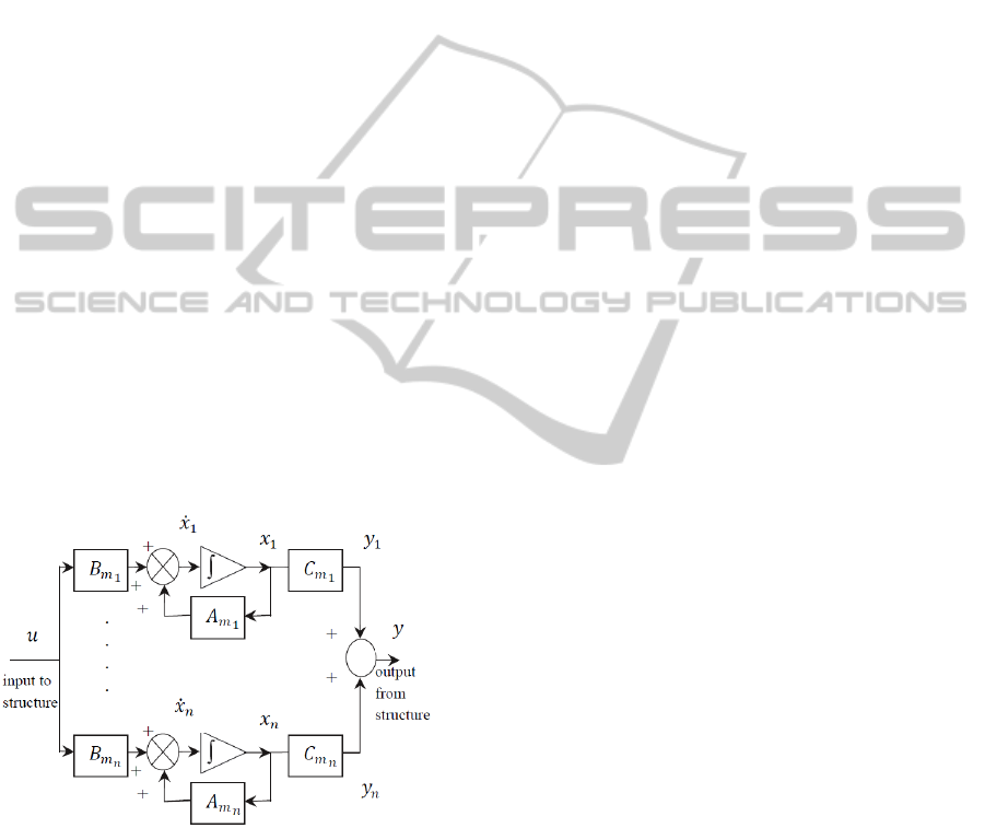
as illustrated in Figure 2.
Figure 2: Block diagram of modal state-space
representation indicating no coupling between modes.
4 ILLUSTRATIVE EXAMPLE
Consider the simple two-member structure in Figure
1 and described in Section 3.1.
Using matrices (3) and (4) it is clear that
and
are symmetric and that
is positive definite
(with successive determinant minors being positive)
and
represents proportional damping. In the
nodal coordinate representation ,and represent
displacement, velocity and acceleration of two
nodes. In this case
i.e. the number of
degrees of freedom in terms of nodes is equal to the
number of modes, with each mode being a natural
frequency of the combined structure.
Consideration is now given to equation (7), for
the non-trivial case, i.e. ϕ0. So that the
eigenvalue problem det
= 0, = 1, 2,
is to be solved, where
denotes the square of the
natural modes or frequencies in rad/s. Noting the
form of
and letting the
for = 1, 2, the
equation can be re-stated in the normal eigenvalue
form
0
(32)
yielding
= 5.236 and
= 0.764, which are real
positive and distinct. These are necessarily positive
due to the fact that
. Hence the natural
frequencies are:
2.288 rad/s and
0.874
rad/s, so that
2.288 0
0 0.874
and
5.236 0
0 0.764
(33)
The eigenvectors in equation (7) corresponding to
the
are denoted ϕ
and these are obtained
from
ϕ
0
(34)
It can be deduced that for
and
ϕ
1.618ϕ
ϕ
0.618ϕ
(35)
The modal matrix Φ in standard form may thus be
expressed as
Φ
1.0 0.618
0.618 1.0
(36)
(In standard form the largest element in each ϕ
is
normalised to unity.)
It should be noted that these eigenvectors are not
unique and can be replaced by any arbitrary non-
zero scalar multiples.
It is sometimes convenient to normalise the
vectors such that the Euclidian norm is equal to
unity, but this is not considered here. However,
noting that Φ
has the same diagonalising properties
asΦ
, i.e. the inverse of the modal matrix, Φ
is
used in the example in place ofΦ
, see Section 3.3.
ICINCO2013-10thInternationalConferenceonInformaticsinControl,AutomationandRobotics
482
Consider the modal state-space representation (24)
to (28), where it can be shown that:
01
2
01
2
0
0
(37)
10
00
10
01
(38)
,
are the ith model displacement and
velocity, respectively.
The poles of each modal property are the
complex conjugate pairs, for 1,2
1
(39)
1
(40)
Applying the similarity transformation Φ
Φ it
may be deduced that the resulting damping in the
modal representation is given by
0.05236 0
0 0.00764
(41)
Making use of and
from (33) and combining
with from (41) and substituting into (37), it may
be deduced that
is given by
0 1
5.236 0.240
01
0.764 0.0134
(42)
and, using (16), the input vector
is given by
0
0.447
0 0.724
(43)
To illustrate the modal control approach, attention is
given to increasing both the damping and the natural
frequency of the triple
,
,
such that
and
are given by 1.748 rad/s and 0.0153,
respectively, hence increasing their values by a
factor of 2.
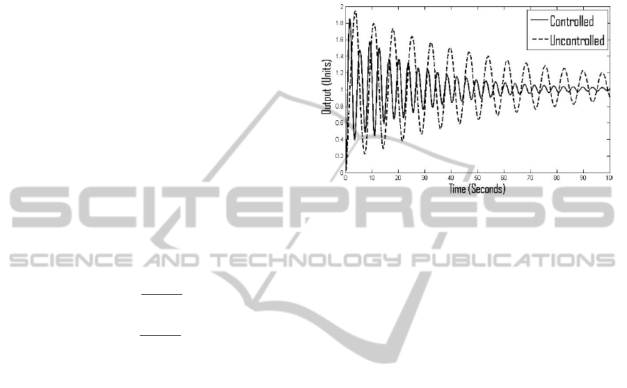
Figure 3 shows the uncontrolled response of the
flexible structure and the effect of modal control
applied to the triple
,
,
, on the overall
performance. The controller satisfactorily achieves
the required damping and natural frequency for the
second mode without changing that of the first.
Figure 3: Illustrating the application of modal control to
the example of Figure 1.
The above example has served to illustrate that it is
possible via modal control to independently change
a mode of a given structure without affecting the
other modes.
5 CONCLUSIONS
The paper has provided a premise statement and has
made assumptions on the factors influencing future
design of the passenger vehicle fleet. Based on these
assumptions, new generations of vehicles will be
lighter, able to achieve CO
2
emission reductions and
also, because such vehicles will be equipped with
advanced driver assisted systems and active safety
devices, will become more efficient, safer and
environmentally friendly.
The presence of the lighter vehicles in the fleet
prompts the need for optimum energy absorption
between vehicles of dissimilar masses. Smart
materials provide a means of achieving these
desirable mechanical/structural properties given a
particular collision scenario. As such larger vehicles
will be required to soften upon impact and give way
to smaller vehicles which, contrary to current
practice, will be allowed to stiffen. Consequently,
collision energy mitigation control strategies need to
respond rapidly in advance, making use of predictive
and adaptive procedures, with full exploitation of
vehicle to vehicle communication and onboard
safety systems. The need for the current levels of
crashworthiness and the accompanying crumple
zones in future vehicles is therefore challenged. In
CollisionEnergyMitigationthroughActiveControlofFutureLightweightVehicleArchitectures
483

fact it is argued that reduced aggressivity among
colliding vehicles should replace crashworthiness as
a key future safety design criteria.
The paper has provided a convincing case for
developing future lighter vehicles with advanced
safety features, capable of mitigating the effects of
collisions via active control of onboard smart
materials to achieve maximum energy absorption.
The future vehicles described above will also meet
the increased demands regarding CO
2
legislation,
which must be achieved to develop an economic,
efficient, safe and sustainable transport system for
future generations.
The resulting design represents a radical
paradigm shift from current automotive industry
practice. Whilst this may be met with scepticism
from some quarters, it will be embraced and seen as
a sustainable approach for achieving CO
2
reduction,
lightweight structures, cooperative vehicles and
enhanced active safety systems. All of which
represent key goals along a road map towards
achieving improved/sustainable future vehicle
engineering systems.
REFERENCES
Berger, L., Lesemann, M., Sahr, C., 2009. Superlight-car –
the multi-material car body, 7
th
European LS-DYNA
Conference.
Ellis, M., 2011. Material selection & application for future
low carbon vehicles, Aluminium Federation
Automotive Conference.
Eugensson, A., 2009. Volvo Vision 2020. Available from
http://www.unece.org/fileadmin/DAM/trans/roadsafe/
unda/Sweden_Volvo_Vision_2020.pdf
Gabbert, U., 2002. Research activities in smart materials
and structures and expectations to future
developments, Journal of Theoretical and Applied
Mechanics. Versita.
Ghassemieh, E., 2011. Materials in automotive
application, State of the art and prospects. New Trends
and Developments in Automotive Industry. InTech.
Gupta, P., Srivastava, R.K., 2010. Overview of multi
functional materials. New Trends in Technologies:
Devices, Computer, Communication and Industrial
Systems. InTech.
Hickman, R., Bannister, D., 2006. Looking over the
horizon. Transport and reduced CO
2
emissions in the
UK by 2030. Association for European Transport and
contributions.
Hunkeler, S., Duddeck, F., Rayamajhi, M., Zimmer, H.,
2013. Shape optimisation for crashworthiness
followed by a robustness analysis with respect to
shape variables. Journal of the International Society
for Structural and Multidisciplinary Optimisation.
Springer.
Jawad, S. A., 2003. Protecting small cars and mitigating
severe crashes – Smart structure solution. 18
th
International Technical Conference on the Enhanced
Safety of Vehicles. Transportation Research Board.
Leo, D. J., 2007. Engineering Analysis of Smart Material
Systems. John Wiley & Sons.
Lotus., 2010. An assessment of mass reduction
opportunities for a 2017-2020 Model Year Vehicle
Program. The International Council of Clean
Transportation.
Schmidt, B., Haight, W. R., Szabo, T., Welcher, J., 1998.
System-based energy and momentum analysis of
collisions. SAE paper 980026.
Thatcham., 2012. Thatcham Research News. Special
Edition 10/No. 7.
Wilkinson, J. H., 1965. The Algebraic Eigenvalue
Problem, Oxford University Press.
ICINCO2013-10thInternationalConferenceonInformaticsinControl,AutomationandRobotics
484
