
Epipolar Geometry for Vision-guided Laser Surgery
Nicolas Andreff, Sounkalo Demb
´
el
´
e, Brahim Tamadazte and Zill-e Hussnain
Institut FEMTO-ST, Universit
´
e de Franche-Comt
´
e/CNRS/ENSMM/UTBM, 24 rue Savary, 25000 Besanc¸on, France
Keywords:
Laser Surgery, Visual Servoing, Epipolar Geometry.
Abstract:
This paper proposes to use the analogy between a scanning laser beam and a camera. Thereby, a degenerate
stereoscopic system can be defined by such a virtual camera and a real camera observing the laser spot on
the tissues. This system can be mathematically described by means of epipolar geometry. From the latter,
a vision-based control law which has no any matrix inversion nor estimation of the 3D scene is developed.
According to the first results of simulation, the proposed control law shows an exponential convergence and
robustness with the presence of noise in the sensors signals.
1 INTRODUCTION
µRALP is an European FP7-ICT project that involves
the development of a system for endoluminal laser
phonosurgery, i.e. surgery of the vocal chords using
an incision laser emitted from fiber optics inside the
larynx (Fig. 2). Unlike µRALP project, in current la-
ryngeal laser surgical procedures, a beam of incision
laser is projected to target position on the soft tissue,
from the working distance of 400mm by means of a
rigid laryngoscope (Fig. 1). This yields safety con-
cerns for the patient and staff due to the fact that laser
beam follows an uncovered path toward surgical site
as shown in the Fig. 1, as well as limitations to ac-
curacy, since a large working distance limits the min-
imum accuracy achieved by a typical laser scanner.
Moreover, this so-called laryngeal suspension posture
of the patient requires an extreme stretching of the
neck, which makes current surgical procedure painful
even several days after the operation.
Figure 1: Current laryngeal laser surgery setup.
One such laryngeal laser surgical system is the
AcuBlade
TM
. It claims to be a robotic system because
it features fully autonomous pattern following (line
and arc for resection, circle for ablation) by the laser
spot, once the surgeon has defined the dimension and
the position of the pattern intraoperatively based on
direct visualization (through the stereomicroscope) of
the operating site. Thus, the laser spot is automat-
ically controlled. So by competitive rationalism the
objective of µRALP is also to automate the control of
the laser phonosurgery, which is totally in line with
the industrial and medical practices in the field.
Yet, in the AcuBlade system, the laser spot is
controlled in an open-loop mode from the surgeon’s
viewpoint. Once the surgeon has chosen the pattern
parameters, the robot follows it blindly, relying on
its internal calibration and sensors. Any deviation
from this plan is forbidden (to the exception of the
foot pedal switch of the power laser). The movement
of the target tissue during surgery can bring incorrect
target position under projected laser beam, and when
surgeon realizes, it may be too late to switch off the
incision laser using foot pedal. Indeed, during the ab-
lation and the resection, the tissue moves(by breathing
or heart beat) and deforms (due to resection). There-
fore, the planned pattern must be very small and can-
not guarantee high accuracy. Furthermore, in case of
an endoscopic laser steering system (Fig. 2), one can-
not guarantee any time stability of the microrobot cal-
ibration.
The only way to increase the accuracy and the ex-
tension of the patterns is to close the control loop over
an exteroceptive sensor, namely the imaging system.
Closing the control loop over a camera is known as
471
Andreff N., Dembélé S., Tamadazte B. and Hussnain Z..
Epipolar Geometry for Vision-guided Laser Surgery.
DOI: 10.5220/0004595904710476
In Proceedings of the 10th International Conference on Informatics in Control, Automation and Robotics (ICINCO-2013), pages 471-476
ISBN: 978-989-8565-71-6
Copyright
c
2013 SCITEPRESS (Science and Technology Publications, Lda.)
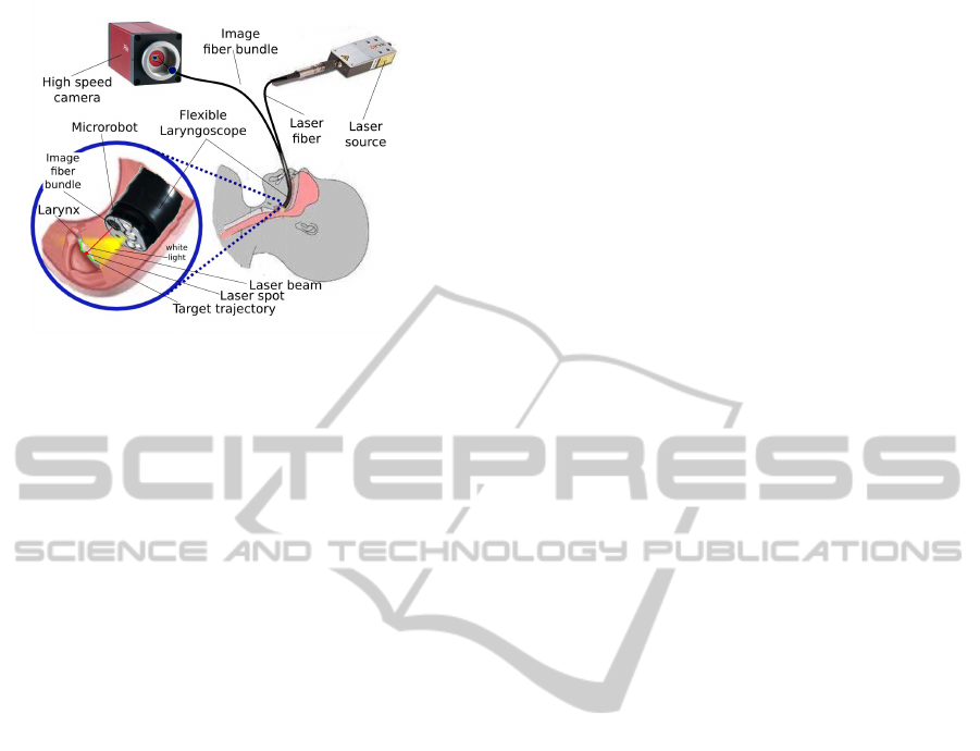
Figure 2: Endoscopic laser microphonosurgery.
visual servoing, known as being a technique robust to
calibration errors and dynamics of hand-and-eye co-
ordination.
Visual servoing has been used in minimally inva-
sive surgery to perform two types of applications. The
first type is relative to tissue motion tracking and com-
pensation. By opposition to industrial objects, hu-
man tissues are alive and have tendency to move by
breathing or beating heart motions. These physiolog-
ical motions complicate the task of the surgeon, and
their compensation improves the precision of surgical
interventions. The second type of applications deals
with tracking and guidance of surgical instruments. In
this case, the objective is more classical for visual ser-
voing: positioning of a target by using vision-based
feedback control.
1.1 Motion Compensation
In motion compensation using image-based control
strategy, the motion of issue is estimated from im-
ages delivered by the vision system and compensated
by means of a robotized instrument. Gangloff and
his colleagues have developed an active beating heart
stabilizer by using a predictive control scheme (Gin-
houx et al., 2005) and a robust control scheme (Bachta
et al., 2011). They obtained interesting results with
simulation experiments as well as in-vivo experimen-
tal tests with pigs. In both cases the acquisition rate
reached 500 Hz. In (Krupa et al., 2009), the authors
used visual servoing and speckle information in ultra-
sound images at 12 Hz to stabilize a probe in a re-
gion of interest. Simulation experiments have been
used to validate the developments. In (Kesner et al.,
2010), the authors integrated heart motion compen-
sation in the 3D positioning of a catheter using 3D
ultrasound images. A Kalman filtering has allowed
to take into account the 50-100 ms delay of acqui-
sition and a tracking error of 0.77 mm was obtained
with in-vivo tests with pigs. In (Chen et al., 2010) a
virtual bone clamper is achieved by means of visual
servoing with a stereovision system running at 10 Hz
associated to a Kalman filtering. The core of these
applications is motion tracking and for that solutions
already developed in machine vision can be used: cor-
relation (Ortmaier et al., 2005), Lucas-Kanade tracker
or SURF (Elhawary and Popovic, 2011).
1.2 Instrument Guidance
In instrument guidance by means of visual servoing
many developments have been reported in the litera-
ture. In 2003, Krupa et al. (Krupa et al., 2003) pro-
posed the use of image-based visual servoing to per-
form 3D positioning of a surgical instrument. But
only simulation experiments were performed with
a camera running at 50 Hz and a phantom instru-
ment. The same group proposed the 3D positioning
of a probe using visual servoing in ultrasound im-
ages: image-based visual servoing on a simulation
set-up in (Krupa and Chaumette, 2006), visual ser-
voing using moments on simulation set-up running at
25 Hz (Mebarki et al., 2010). In (Becker et al., 2010),
the authors have developed a semi-automated laser in-
traocular surgery. Their set-up included a laser probe
attached to a micromanipulator, a stereovision system
working at 30 Hz, a 3D sensor running at 2 kHz and
a control system running at 1 kHz. All the applica-
tion aspects were presented: preoperative procedure
for the selection of the sites to burn, calibration of
stereovision device using the data of the 3D sensor,
3D surface reconstruction and registration of current
images with preoperative images, PID control of the
micromanipulator to position the laser on the site to
burn. Note that the control is a PID in the 3D space
over the triangulated laser spot.
In (Mattos and Caldwell, 2012) and (Dagnino
et al., 2012), Mattos describes their experiments in
laser phonomicrosurgery. They have integrated com-
plete equipment including laser sources, micromanip-
ulators to control the position of the laser beam, an
optical microscope to view and record the images and
a haptic device. They also developed different algo-
rithms to track the laser spot following a predefined
path. For the moment, these works treat the problem
in a static point of view, thus the dynamics aspects of
the systems (3D tissue, tissue movement, kinematic
model of microrobot, etc.), were not included in the
study. In (Reilink et al., 2010), the authors used di-
rectly images delivered by an endoscope to guide it
inside the body. Simulation experiment show an im-
provement of 68% with respect to manual steering.
ICINCO2013-10thInternationalConferenceonInformaticsinControl,AutomationandRobotics
472

Figure 3: Schematic view of the laser steering system.
1.3 Related Developments
In addition to the literature above dealing with visual
servoing directly, it is also necessary to cite the refer-
ences (Ota et al., 2009; Rivera-Serrano et al., 2012)
which describe the development of a flexible robot
for transoral surgery. It is a snake-like mechanism of
10 mm diameter, 300 mm long including 105 degrees-
of-freedom. It is endowed with a 15 K fiber bundle
connected to a 640×480 pixels camera, an illumina-
tion source, and two 4.2 mm tool ports. It has been
possible to introduce it in cadavers without laryngeal
suspension, to observe vocal folds and to perform a
retraction and cauterization on the base of the tongue.
However, the system is only working in teleoperated
mode which might limit its accuracy with respect to
the delicate phonosurgery requirements. Such a sys-
tem should thus be enhanced by adding visual servo-
ing and, probably also, a laser by replacing the cur-
rently used mechanical scalpel.
1.4 Contributions
The contribution of this paper is to discuss the con-
trol of a laser (namely, the invisible incision laser for
incision with co-axial visible red color Helium–Neon
laser pointer) over the vocal folds, and by extension,
the control of a laser over any surface. It shows that
the geometrical relation between laser scanner and
camera can simplify the control of microrobot (for
laser scanner): no matrix inversion, no explicit knowl-
edge or reconstruction of the 3D scene.
2 VISUALLY-GUIDED LASER
SURGERY
In this section, we analyze the control of the laser
spot with the microrobot using an optic fiber bundle to
bring the image of the scene onto a high-speed camera
(see Fig. 2 and Fig. 3).
This control can be done in two ways: using the
standard visual servoing equations or using the above
grounding analogy.
2.1 A Word on Standard Control
Let us note z the direction of the laser beam reflecting
from the steering mirror towards the vocal fold, P the
position of the laser spot on the tissue surface, and p
the position of the laser spot in the image. Then, it is
trivial to write, in the reference frame R
0
, attached to
the zero-reference of the steering mirror, the follow-
ing equation:
0
P = d
0
z (1)
where d is the distance traveled by the laser from the
mirror to the tissue.
This distance cannot be measured, to the contrary
of
0
z which can be obtained from the microrobot en-
coders. However, it can be modeled if one approxi-
mates the tissue surface in P by a plane equation:
0
n
T 0
P − d
0
= 0 (2)
where
0
n is the orientation of the surface normal in R
0
and d
0
is the distance of the plane to the origin of R
0
.
Using this model, one finds:
d =
d
0
0
n
T 0
z
(3)
On the other hand, the perspective projection
equation yields:
˜p = K
c
P
Z
(4)
where K is the matrix containing the camera intrinsic
parameters, P is now expressed in the camera frame
R
c
, Z is the unmeasured depth along the line of sight
passing through p as well as the third coordinate of
c
P and ˜p represents the homogeneous coordinates of
p.
To apply, the usual visual servoing approach, one
needs to differentiate the latter with time (ie. time-
derivation):
˙
˜p =
1
Z
K
1 0 −X/Z
0 1 −Y /Z
0 0 0
c
˙
P (5)
where X, Y , and Z are the 3D coordinates of
c
P.
It is possible to obtain another expression of
c
˙
P by
differentiating (1):
0
˙
P =
˙
d
0
z + d
0
˙z (6)
and expressing the latter in R
c
:
c
˙
P =
c
R
0
˙
d
0
z + d
0
˙z
(7)
EpipolarGeometryforVision-guidedLaserSurgery
473

Figure 4: Analogy with stereoscopy.
Now, from (3), one gets (under the simplifying as-
sumption that the surface plane does not change):
˙
d = −
d
0
0
n
T
(
0
n
T 0
z)
2
0
˙z (8)
Putting (7) and (8) into (5) allows to obtain
˙
˜p un-
der the following form:
˙
˜p = L(d,Z,
0
n,d
0
,
c
R
0
, p,
0
z)
0
˙z (9)
where L is of dimension 3 × 3. The inversion of
the latter allows to convert the image velocity of the
laser spot into the velocity of the laser beam, which,
in turn, shall be converted into microrobot velocity
through the differential inverse kinematic model.
Therefore, this controller needs the estimation of
d and Z, which can be obtained by triangulation be-
tween the laser beam (known from the joint values q),
the line of sight outgoing from the camera through the
laser spot projection ( p) and the robot-camera calibra-
tion.
We have not implemented this controller, nor
pushed further the details of the calculation (so far),
because there is a more elegant way of treating the
problem, which does not require any explicit triangu-
lation nor matrix inversion.
2.2 Laser Visual Servoing using
Epipolar Geometry
On the opposite to the above method, which is totally
generic, our approach, detailed, below is totally hand-
made and tailored to the specific case of a laser beam
being observed by a camera.
Indeed, the set-up in Fig. 3 is analogous to a de-
generate case of epipolar geometry in Fig. 4: the
steering mirror is similar to a virtual camera whose
optical centre corresponds to the centre of rotation of
the mirror. Thereby, points p and p
0
are the images of
the same spatial point P and are hence linked by the
epipolar constraint:
˜p
0>
F ˜p = 0 (10)
where F is the fundamental matrix of the two-view
system (Hartley and Zisserman, 2006). Actually, this
epipolar constraint is defined up to a scale factor, and
thereby, ˜p
0
can be replaced by
0
z, the unit vector de-
scribing, in the microrobot base-frame R
0
, the direc-
tion of the laser beam from the mirror to the vocal
fold:
0
z
>
F ˜p = 0 (11)
This equation expresses the fact that the origin of
the camera, the pivot point of the microrobot, the laser
beam, the line of sight and the laser spot on the tissue
are coplanar. It can be also interpreted in three ways:
0
z ⊥ F ˜p (12)
˜p ⊥ F
> 0
z (13)
and both F ˜p and F
> 0
z represent the (non-unit) nor-
mal vector to the epipolar plane in the micro-robot
and the camera frame, respectively.
The time derivative of the epipolar constraint
which is given by:
(F
> 0
z)
>
˙
˜p + (F ˜p)
> 0
˙z = 0 (14)
Now, we can decompose
0
˙z
into a component or-
thogonal to the epipolar plane and a component inside
the latter:
0
˙z = α
0
h + β
0
z ×
0
h (15)
where
0
h =
F ˜p
kF ˜pk
. Replacing this expression into the
epipolar constraint and reordering the terms, we get:
α = −
(F
> 0
z)
>
kF ˜pk
˙
˜p (16)
Actually, α only depends on the projection of
˙
˜p
onto the normal to the epipolar plane, but expressed
in the camera frame, i.e. along
c
h =
F
> 0
z
kF
> 0
zk
. Thus,
the remaining part of
˙
˜p is obtained by canceling this
projection:
˙
˜p = a
c
h + (I
3
−
c
h
c
h
>
)
˙
˜p (17)
where the value of a does not have any interest for the
sequel, but can be related to α by inserting the latter
equation into the former.
Now, concentrate on the part of
˙
˜p lying in the
epipolar plane. In (17), it is expressed in the cam-
era frame, so we just need to bring it back to the mi-
crorobot frame, going backwards the camera intrinsic
parameters, the orientation of the camera frame with
respect to the microrobot frame and compensating for
the unknown scale factor in F, to get β:
β =
kF
> 0
zk
kF ˜pk
(
0
z ×
0
h)
>0
R
c
K
−1
(I
3
−
c
h
c
h
>
)
˙
˜p
(18)
ICINCO2013-10thInternationalConferenceonInformaticsinControl,AutomationandRobotics
474

As a consequence, we have expressed
0
˙z as a
function of
˙
˜p:
0
˙z =
n
(
0
z ×
0
h)(
0
z ×
0
h)
>0
R
c
K
−1
(I
3
−
c
h
c
h
>
)
−
0
h
c
h
>
o
kF
> 0
zk
kF ˜pk
˙
˜p (19)
Consequently, we have the exact expression of
the conversion of the image velocity into the laser
beam velocity, without any matrix inversion, nor any
explicit triangulation or scene structure knowledge.
This expression only depends on the measurements
(
0
z and p), the fundamental matrix F and a reduced
set of calibration parameters (K and
c
R
0
). Geometry
is always useful !
Now, we can come up to the control law, by en-
forcing a first order behavior of the error in the image
between the current and the desired projections of the
laser spot in the image:
˙
˜p = −λ( ˜p − ˜p
∗
) (20)
with ˜p
∗
the set point and λ the control gain.
The joint space control of the microrobot is given
by:
˙q = J
−1 0
˙z (21)
where J
−1
is the inverse kinematic Jacobien of the
microrobot.
3 SIMULATION RESULTS
The experimental validation of the proposed approach
consists of a simulator before a real implementation
on an experimental setup. The used simulator was im-
plemented using the Open Source C++ Library: ViSP
(Visual Servoing Platform) (Marchand et al., 2005).
So, in first case, we have studied the convergence
of the proposed control law in perfect conditions (no
noise). Figure 5 illustrates the expected exponen-
tial decay of the image errors on both microrobot’s
degrees-of-freedom vs. the time variation.
Figure 5: Time evolution of the image errors.
In order to test the robustness of the proposed
control law, we have added Gaussian white noise to
Figure 6: Time evolution of the image errors with error
measurements (ie. with added noise).
the sensors signals ( ˜p
∗
and
0
z). Therefore, Figure 6
shows that the control law remains efficient and con-
verges exponentially to zero despite the presence of
noise on the measurements.
4 DISCUSSION
Under real conditions of endoscopic phonomicro-
surgery using a laser, the surgeon sets a 3D path onto
the vocal cords to be followed by the laser with a
high accuracy. However, the proposed approach does
not include the trajectory tracking in the mathematical
formulation of the control law. Therefore, it should
be complemented by an additional term for trajectory
tracking purpose ( ˜p
∗
(t)), including constraints on the
tissue exposure to laser, in order to avoid any car-
bonization. Further investigation of geometry, namely
the trifocal geometry associated to a stereoscopic ob-
servation of the laser spot, is expected to further sim-
plify the control and to increase its robustness, which
is a key issue in the transfer of automation into actual
clinical devices. Also, many micromanipulators have
a parallel kinematics architecture, which can be con-
trolled without having joint encoder values as feed-
back (Andreff and Martinet, 2009). Consequently,
using the proposed multi-view geometric approach
might enable simplified miniaturization of laser steer-
ing in an endoscopic set-up, because one can de-
sign steering parallel kinematics mechanisms with-
out proprioceptive sensors. This is a very crucial in-
vestigation field, since endoscopic laser surgery faces
very contradictory requirements in terms of sweep-
ing range and frequency (yielding larger mechanisms)
and of available space at the endoscopic tip.
5 CONCLUSIONS
In this paper, it was shown that resorting to geometry
simplifies the eye-to-hand control law for a surgical
EpipolarGeometryforVision-guidedLaserSurgery
475

laser (and any other application where a beam needs
be accurately swept over a surface), by essentially re-
moving the need for on-line estimation of the 3D sur-
face. Actually, if a dedicated surgeon-robot interface
is designed (Mattos and Caldwell, 2012) to define the
desired trajectory in the image, then the latter will ge-
ometrically contain a coherent description of the 3D
surface. And thus, the 3D information is not purely
and simply thrown away as it could seem but, rather,
it is implicitly used. The first obtained results of the
simulation validation shows the relevance of the pro-
posed approach. It provides a good convergence (ex-
ponential decay of the errors image) and robustness
with respect to the presence of noise in the sensor sig-
nals. In the future, we will work on demonstrating
the stability of the visual servoing control law and its
validation on a testbench which includes a camera, a
commercial laser and a micromirror equipped with a
two degree-of-freedom scanner from PI (Physical In-
struments Inc.). This is before considering validation
tests on anatomical specimens
ACKNOWLEDGEMENTS
This work was supported by µRALP, the EC
FP7 ICT Collaborative Project no. 288663
(http://www.microralp.eu), and by ACTION, the
French ANR Labex no. ”ANR-11-LABX-01-01”
(http://www.labex-action.fr).
REFERENCES
Andreff, N. and Martinet, P. (2009). Vision-based self-
calibration and control of parallel kinematic mecha-
nisms without proprioceptive sensing. Intelligent Ser-
vice Robotics, 2(2):71–80.
Bachta, W., Renaud, P., Laroche, E., Forgione, A., and
Gangloff, J. (2011). Active stabilization for robotized
beating heart surgery. IEEE Transactions on Robotics,
27:757–568.
Becker, B. C., MacLachlan, R. A., Jr, L. A. L., and Riviere,
C. N. (2010). Semiautomated intraocular laser surgery
using handheld instruments. Lasers in Surgery and
Medicine, 42:264?273.
Chen, C.-S., Hsieh, M.-S., Chiu, Y.-W., Tsai, C.-H., Liu,
S.-M., Lu, C.-C., and Yen, P.-L. (2010). An uncon-
strained virtual bone clamper for knee surgical robot
using visual servoing technique. Journal of the Chi-
nese Institute of Engineers, 33(3):379–386.
Dagnino, G., Mattos, L. S., and Caldwell, D. G. (2012).
New software tools for enhanced precision in robot-
assisted laser phonomicrosurgery. In 34th An-
nual International Conference of the Engineering in
Medicine and Biology Society (EMBC’12).
Elhawary, H. and Popovic, A. (2011). Robust feature track-
ing on the beating heart for a robotic-guided endo-
scope. The international journal of medical robotics
and computer assisted surgery, 7:459–468.
Ginhoux, R., Gangloff, J., de Mathelin, M., Soler, L.,
Sanchez, M. M. A., and Marescaux, J. (2005). Ac-
tive filtering of physiological motion in robotized
surgery using predictive control. IEEE Transactions
on Robotics and Automation, 21(1):235–246.
Hartley, R. and Zisserman, A. (2006). Multiple view geom-
etry in computer vision. Cambridge University Press,
Cambridge, United Kingdom, 2nd edition edition.
Kesner, S. B., Yuen, S. G., and Howe, R. D. (2010). Ul-
trasound servoing of catheters for beating heart valve
repair. In IPCAI, pages 168–178.
Krupa, A. and Chaumette, F. (2006). Guidance of an ultra-
sound probe by visual servoing. Advanced Robotics,
20(11):1203–1218.
Krupa, A., Fichtinger, G., and Hager, G. D. (2009). Real-
time motion stabilization with b-mode ultrasound us-
ing image speckle information and visual servoing. In-
ternational Journal of Robotics Research.
Krupa, A., Gangloff, J., Doignon, C., de Mathelin, M. F.,
Morel, G., Leroy, J., Soler, L., and Marescaux, J.
(2003). Autonomous 3-d positioning of surgical in-
struments in robotized laparoscopic surgery using vi-
sual servoing. IEEE Transaction on Robotics and Au-
tomation, 19:842–853.
Marchand, E., Spindler, F., and Chaumette, F. (2005). Visp
for visual servoing: a generic software platform with a
wide class of robot control skills. IEEE Robotics and
Automation Magazine, 12(4):40–52.
Mattos, L. S. and Caldwell, D. G. (2012). Safe teleoperation
based on flexible intraoperative planning for robot-
assisted laser microsurgery. In 34th Annual Interna-
tional Conference of the Engineering in Medicine and
Biology Society (EMBC’12).
Mebarki, R., Krupa, A., and Chaumette, F. (2010). 2-
d ultrasound probe complete guidance by visual ser-
voing using image moments. IEEE Transactions on
Robotics, 26(2):296–306.
Ortmaier, T., Groger, M., Boehm, D., Falk, V., and
Hirzinger, G. (2005). Motion estimation in beating
heart surgery. IEEE Transactions on Biomedical En-
gineering, 52(10):1729–1740.
Ota, T., Degani, A., Schwartzman, D., Zubiate, B., McGar-
vey, J., Choset, H., and Zenati, M. A. (2009). A highly
articulated robotic surgical system for minimally in-
vasive surgery. The Annals of Thoracic Surgery,
87(4):1253–1256.
Reilink, R., Stramigioli, S., and Misra, S. (2010). Image-
based flexible endoscope steering. In The 2010
IEEE/RSJ International Conference on Intelligent
Robots and Systems, pages 2339–2344.
Rivera-Serrano, C. M., Johnson, P., Zubiate, B., Kuen-
zler, R., Choset, H., Zenati, M., Tully, S., and
Duvvuri, U. (2012). A transoral highly flexible robot:
Novel technology and application. The Laryngoscope,
122:1067–1071.
ICINCO2013-10thInternationalConferenceonInformaticsinControl,AutomationandRobotics
476
