
Comparison of Active Sensors for 3D Modeling of Indoor Environments
Abdennour Aouina
1
, Michel Devy
1
and Antonio Marin-Hernandez
1,2
1
CNRS, LAAS, Universit
´
e de Toulouse, 7 avenue du Colonel Roche, F-31077 Toulouse Cedex, France
2
Department of Artificial Intelligence, Universidad Veracruzana, Sebast
´
ıan Camacho No. 5, Xalapa, Mexico
Keywords:
3D sensors, Resolution, View Field, Scene Modeling, Acquisition from Mobile Robots.
Abstract:
3D perception has known impressive advances in the past 3 years; it corresponds to several technological
improvements, plus many new development teams providing open sources. First of all, researchers in Robotics
and 3D Perception have made profit of the Kinect sensor; some works were already devoted to 3D cameras,
using more expensive Time-of-Flight optical devices. Another common way to acquire dense 3D data, is by
scanning the environment by a laser range finder (LRF); as for example, the Hokuyo tilting LRF integrated
on the PR2 robot by Willow Garage. To build a dense geometrical model of an indoor environment, several
sensors could be selected in order to acquire 3D data. This paper aims at giving some insights on this selection,
presenting some pros and cons for Kinect, Hokuyo and ToF optical sensors.
1 INTRODUCTION
Environment modeling has become an essential task
for robotics. Particularly for mobile robots, these
models are very useful to achieve many and diverse
tasks, as for example: to simulate real scenarios, to
enable motion planning and mobile robot localization,
only to mention some of them. Depending on their
use, these models could have different forms and rep-
resentations, e.g. probabilistic discrete grids for robot
navigation on flat ground, 3D meshes or voxel maps
for object grasping . . .
Nowadays, the construction of dense 3D represen-
tations has earned more attention. As any model, 3D
models can be represented in different ways, as for
example: points and a graph (octree), planar faces,
digital elevation maps, surface elements (surfel), etc.
Each representation is more suitable or adapted for a
specific purpose or application, i.e. it’s not the same
to model objects in a table than to model large scale
environments like cities. Geometrical 3D informa-
tion are sufficient to locally execute a motion, while
appearance data is required for cognition, interpreta-
tion. . .
Beside the variety of representations, multiple
sensors can be used to acquired raw data to be fused
in these 3D models, such as: stereo-vision systems,
Time-of-Flight (ToF) cameras, Laser Range Finders
(LRF) over pan and/or tilt platforms, and recently the
use of RGB-D cameras, like the Microsoft Kinect sen-
sor. Likewise, each kind of sensors has its advantages
and disadvantages, what makes it more suitable for a
given application or task.
To build a 3D geometrical model with an accuracy
and a resolution required for the planning and the ex-
ecution of robotic tasks, it is mandatory to acquire a
large amount of raw data. Usually ToF cameras or
3D lasers scans allow the construction of dense maps.
Nevertheless, their construction is a very hard task.
Coupled with the problem of large data storage, 3D
modeling from data acquired while moving the sen-
sor in the environment, is often performed as an off
line process.
In this work, we are interested in the construc-
tion of 3D models from indoor human environments.
Our primary goal is to recover large planes describ-
ing the rigid environment infrastructure (walls, floor,
ceiling. . . ) and some large and moveable objects like
doors, tables, etc. Modeling has to be achieved on
line from data acquired by sensors embedded on a
mobile robot; so it is basically a Simultaneous Lo-
calization and Mapping (SLAM) problem. However
it is proposed to construct the 3D environment model,
separately from the SLAM map, i.e. the classical 2D
models (e.g. occupancy grids) built for example by
Gmapping or the sparse 3D models (e.g. 3D visual
landmarks) built for example by PTAM. Having suc-
cessful efficient and real-time methods to cope with
SLAM, our proposal aims at adding a layer of extra
3D and dense information, consistent with the rep-
442
Aouina A., Devy M. and Marin-Hernandez A..
Comparison of Active Sensors for 3D Modeling of Indoor Environments.
DOI: 10.5220/0004485004420449
In Proceedings of the 10th International Conference on Informatics in Control, Automation and Robotics (ICINCO-2013), pages 442-449
ISBN: 978-989-8565-70-9
Copyright
c
2013 SCITEPRESS (Science and Technology Publications, Lda.)

resentation built by an existing SLAM method, but
without increasing its complexity.
Three different sensors have been analyzed and
characterized to achieve the proposed task: a Kinect
RGB-D sensor, a ToF (SR3000) optical camera and
a Tilting LRF (Hokuyo). Appearance-based informa-
tion obtained typically using texture mapping, are not
considered in this paper. In the following section,
we will describe some of the most interesting related
works, followed by a section dedicated to analyze the
main characteristics of the mentioned sensors. In sec-
tion 4, are presented, some evaluations in order to be
able to chose the correct sensor for the task, and in
section 5 we present experimental results, using the
PR2 robot.
2 RELATED WORKS
In recent years, 3D modeling and mapping has be-
come one of the most interesting subjects of research
all along the world. 3D sensors allow to extract the
richness of geometric features, presents in most of the
environments. The construction of 3D models could
be done in many different ways, depending on the
type of environment, the sensor used and applications.
In (Trevor et al., 2012) the problem of 3D model-
ing is considered as a part of SLAM techniques. In
this work, it is used a 3D sensor (a tilting LRF or a
Kinect like sensor) to extract 3D planar surfaces, that
combined with 2D segments obtained from a 2D scan-
ner at base of a mobile robot, are used to build a map
using the GTSAM library (Dellaert and Kaess, 2006).
In this way, 2D lines and 3D planes with a high level
representation and easy to be annotated with seman-
tic information are a good combination to create an
accurate map with high level features.
In (N
¨
uchter and Hertzberg, 2008) as a part of a
6D SLAM method, point clouds are acquired using a
rotating LRF and registered using ICP. Planes are ex-
tracted from the global 3D point cloud by a RANSAC
method and then with the use of a constraint network
these planes are semantically annotated, i.e. walls,
floor or ceiling.
The problem of environment modeling can be re-
solved considering that robots are already localized,
as in (An et al., 2012). In this work, authors concen-
trate more on the computational part, by proposing a
method for fast planar faces detection using 2D lines
extracted from a tilting LRF over a mobile robot. The
proposed method works in real-time and only stores
the initial and end point of each 2D line to construct
the 3D model.
In (Klaess et al., 2012), it is built a 3D map using
a set of 3D laser scanners acquired at different po-
sitions (stop-and-go method); poses are provided by
the use of the gmapping method (Grisetti et al., 2007).
Then, the global point cloud is refined off-line, by ICP
methods. Finally using surfels (surface elements) the
global dense map is reduced, to be treatable by the
robot.
In (Rusu et al., 2009) a pan rotating LRF has been
used to acquire a point cloud, that it is used to get
a high level semantic model of a kitchen environ-
ment. The model is built off-line and it is used a ma-
chine learning algorithm to classify objects and label-
ing them with semantic information.
In (Wolf and Sukhatme, 2008) a tilting LRF has
been used to get 3D data, machine learning methods
have been applied to classify environment to naviga-
ble and non navigable zones. In (Douillard et al.,
2010) a LRF has used to build a hybrid 3D outdoor
environment model using elevation level and planar
faces. As there is also other works use 3D sensors
to model objects and for surface reconstruction as in
(Newcombe et al., 2011) and (Lai et al., 2011), the
modeled objects are used to build semantic maps or
for pattern and objects recognition, its applications
are generally for image of color and depth recogni-
tion or to help robot to recognize and grasp daily used
objects.
So, as we have seen, there is many works from
here and there that use 3D data for multiple applica-
tions from object to environment modeling, we can
extend to say cities modeling as generalization for
outdoor modeling like (Wolf and Sukhatme, 2008)
and (Douillard et al., 2010). Any way, as we has
already mentioned our goal is the modeling of large
scale indoor or man made environments, where most
of works have used a LRF to acquire 3D data.
Other work have concentrated on the evaluation
of sensors as in (Sturm et al., 2012) or (Henry et al.,
2012), they have studied the case of like Kinect sen-
sor and its use in SLAM. In (Smisek et al., 2011) an
evaluation for Kinect ,ToF camera and stereo vision
has been done.
The results and the conclusions of the evaluation is
different from work to an other, because of the differ-
ence between application and the performance needed
in each application.
In this work, has been considerate the three sen-
sors: a Kinect like sensor, a ToF camera and a LRF
over a tilting platform. We evaluate and present their
performances for 3D modeling in large scale indoor
environments.
ComparisonofActiveSensorsfor3DModelingofIndoorEnvironments
443

3 SENSORS
CHARACTERIZATION
Over all the possible characteristics to study, we have
focus only on ones that have direct influence to our
work, such as: field-of-view, maximal range, resolu-
tion, etc. Characteristics, as intrinsic parameters or
calibration are not developed along this work.
Figure 1: Tilting laser on PR2 robot.
Figure 2: SR3000 ToF camera.
Figure 3: Microsoft Kinect on a PR2 robot.
3.1 Field-of-View and Maximal Range
The most important features to characterize a sensor
for 3D environment modeling are: the field-of-view
and the maximal range; indeed they are two different
features, but as both have direct influence in the effec-
tive area covered by the sensor are going to be treated
together in this section.
Starting with the Kinect, it has a FoV of 57
◦
hor-
izontally by 43
◦
vertically. The maximal range is
∼10m, with a blind zone from 0 to 50 cm. The ToF
camera have a similar maximal range as Kinect, but a
narrow FoV (47.5
◦
horizontally by 39.6
◦
vertically),
the blind zone in front of the ToF camera is almost the
same as the Kinect.
In a different way, the LRF’s have only a linear
FoV between 180
◦
and 270
◦
, depending on the hard-
ware. When it’s used to scan 3D environments, it’s
mounted over a pan or tilt unit, in order to cover the
surface of the complementary axe. When this is done,
it is common to use only 180
◦
and the perpendicu-
lar amplitude depends on the (pan/tilt) unit and/or its
configuration.
We use a PR2 robot from Willow Garage, that al-
lows tilting from -40
◦
to 40
◦
, centered at the hori-
zontal position. On this robot, the tilting LRF can
be switched between two preconfigured modes of ac-
quisition, the first mode provides scans with a FoV of
180
◦
without data intensities; the second mode pro-
vides scans of only 95
◦
with data intensities. The
maximal range for the Hokuyo LRF in the PR2 robot
is 30m, it’s has a blind zone of only 10cm.
Although, the range of data provided from Kinect
goes from 50cm to 10m, it is considered that depth
data beyond 3.5m are useless, or at least for 3D en-
vironment modeling, as mentioned in (Trevor et al.,
2012). The main problem with these data, it’s the
method used for the discretization of depth measures;
problem that will be treated later on this section.
Figure 4: Horizontal surface area covered by the FoV and
maximal range of each sensor. In Green are showed the
Kinect, in blue the SR3000 and in red the LRF. The small
region in black represents the blind zone for Kinect and ToF
camera.
In figure 4 are showed the horizontal FoV for
the three sensors together with their maximal depth
range. Here, has been considered only the usable re-
gion of 3D data for the Kinect sensor. In other words,
data inside the regions shown are considered to have
enough accuracy to be treatable. As can be clearly
seen, the covered zone by the laser range finder is
clearly larger than the region covered by 3D cameras.
For this horizontal projection, the areas covered
for corresponding sensors are: 1413.71m
2
for the
Hokuyo LRF, 12.31m
2
for the Kinect and 41.34 m
2
for the SR3000. It results difficult to evaluate, the
effective volume covered by the FoV and maximal
range, because it depends directly on the type of en-
vironment and objects present.
It results obvious, that corresponding to the FoV
and maximal range of sensors, the LRF cover a
greater region; however, this consideration it is not
enough to select it as the appropriate sensor. As it has
ICINCO2013-10thInternationalConferenceonInformaticsinControl,AutomationandRobotics
444
been said, the acquisition modes for mentioned sen-
sors are different, in addition, there are other features
that have to be considered.
3.2 FoV Resolution
To build an efficient map or model, the spacial res-
olution of data has a major effect on the final result.
A very high resolution (dense maps) can create prob-
lems with data processing and computation time re-
quired; while a low resolution can cause the lose of
details.
The Kinect sensor has a resolution of 640×480
(pixels), while for the ToF camera is 176×144 (pix-
els). The angular resolution for each 3D camera can
be obtained directly from the FoV. Considering the
FoV for both sensors, the Kinect and the SR3000, as
a rectangular projection, it is clear than resolution can
be considered homogeneous inside the corresponding
FoV for both cameras.
In the case of the LRF, we can not talk about
a rectangular resolution (height×width); in fact, the
form of the FoV for the tilting LRF on PR2 is a wedge
of sphere, as it is show in Fig 5. While, the horizontal
angular resolution is well defined (0.25
◦
), the vertical
resolution depends on tilt unit speed. Vertical resolu-
tion can be adjusted by controlling both the amplitude
and the period of the motion from the tilt unit.
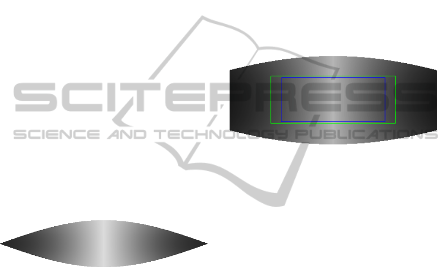
Figure 5: The planar projection of the FoV for the tilting
LRF, the gray scale represents the distribution of sampling
points, where the black correspond to the highest concen-
tration.
We have chosen a vertical amplitude of 80
◦
(-40
◦
to 40
◦
) with a period of 8 seconds; therefore, the laser
completes the 80
◦
area twice in a period (once down-
wards and once upwards), which means that we have
a complete 3D image every 4 seconds. Then, we have
an angular speed of 20 deg/sec for the tilt unit. Be-
ing the frequency of data acquisition 40Hz, we get
a vertical resolution of 0.5
◦
, the double of the linear
resolution.
If it is required a finer resolution, the period can
be increased, however it need to be considered that
if robot is moving, the different linear scans should
be acquire at very different positions. This is the rea-
son why many works dealing with 3D LRF scans does
what is called stop-and-go.
Nevertheless, as the angular surface covered by
the tilting LRF is a wedge, there are regions of it,
where the resolution are greater than others. As we
can see in figure 5 the ends of the wedge concentrate
a very high number of laser samplings.
In figure 6, are showed the projections of the three
fields of view. The FoV of the LRF have been cut
to consider only 95
◦
of the linear sampling. As can
be seen in this figure, the covered surface of the LRF
is greater than others two sensors. In the overlapped
region, the LRF has the less homogeneous sampling
region represented here by the gray scale. While the
regions covered by Kinect and SR3000 are homoge-
neously sampled, the Kinect has more than 3 times
the spatial resolution than the SR30000.
Figure 6: Planar projections of the FoV: in gray scale is the
FoV (95
◦
×80
◦
) for the LRF, green rectangle correspond to
Kinect (57
◦
× 43
◦
) and blue to the SR3000 (47.5
◦
× 39.6
◦
).
Even than, the ToF camera has the lowest resolu-
tion between the 3 sensors, it has been used in some
works for mapping and SLAM, as in (May et al.,
2009),
The Kinect has the better angular resolution, how-
ever it has the problem of accuracy in the regions be-
yond the 3.5 m. We will discuss this point with more
details in a next part of this paper.
3.3 Discretization of Depth
Measurements and Accuracy
Depending on the hardware, depth data are coded and
returned in a different way. We refer in this work, the
discretization of depth measurements, as the way as
different hardware codify and return depth measures.
The LRF and the ToF camera codify the depth
measure as a single float value. In this way, the dis-
cretization step between two consecutive measures is
uniform; being greater the uncertainty (±50mm for
the LRF and ±10mm for the SR3000) than the depth
step discretization.
In an opposite way, Kinect assigns 11 bits to each
depth value returned. 10 bits are used to codify depth
values, corresponding to only 1024 levels of depth
and the 11th bit is used to signal a non disparity mea-
sure or a depth measure error (Khoshelham and El-
ComparisonofActiveSensorsfor3DModelingofIndoorEnvironments
445

berink, 2012), represented by NaN (Not-a-Number
value).
The difference between two successive levels of
depth values is not constant; as it is shown in fig-
ure 7, it follows a quadratic function. In other words,
the empty space between layers becomes greater each
time points are farther from sensor. These layers form
flat slices perpendicular to the Z axe (the optical axe
of sensor). The distance between slices begins with
few millimeters and it’s increased up to 25cm at 10m.
This is the reason why, most of works take into
consideration only points with depth values lower
than a certain threshold; where the empty space be-
tween layers can be accepted. Most of the works,
take this limit as 5m, where distance between lay-
ers is lower than 10cm; however, in other works, as
in (Trevor et al., 2012), this limit was chosen equal
to 3.5m; region where the distance between bands is
lower than 5cm, the uncertainty of LRF.
Figure 7: Depth step discretization in function of the depth.
In figure 8 are shown, the 3D points corresponding
to a wooden board of size of 2m × 1m, acquired at
different distances.
We can see clearly the effect of the non unifor-
mity of depth discretization. The point cloud can be
accepted for 4m distance, but for above of 5m, it can
not be, because of wide gaps between flat slices.
3.4 Data Structure
We refer to data structure as the way as the raw data
are provided by each sensor, before processing it.
3D cameras as its name refers, return a structured
matrix or image of N by M; depending on sensor, as
have been described previously, data are coded in a
different way. Kinect returns an image where each
pixel is a value of 11 bits, and for the SR3000 each
pixel is a single float value. Kinect sensor also returns
an RGB image corresponding to the same region, so
RGB-D data can be recovered from it.
The case of the LRF is different, the measure-
ments are in form of scan lines with depth information
coded in single float values, that can be transformed
to 3D Cartesian coordinates. The use of a scan line,
can not be exploited to build 3D model because all
3D points are aligned, we can get segments as in (An
et al., 2012) but not planes; This is the reason why
most of works collect set of lines together, to create
an image that will be exploited as depth image; but to
create a depth image as it is acquired by a 3D camera
it is needed to keep the robot stopped, what it is called
the stop-and-go method.
In a practical point of view, it is more conve-
nient to use 3D cameras than to hold the mobile robot
stopped for a while to get the complete depth image.
However, due to its restricted FoV it should be re-
quired more 3D images to cover the complete scene
as it should be recovered from LRF.
3.5 Memory Space
The memory space required for each sensor depends
on most of the previous characteristics, specially the
resolution and data structure. The data we talking
about in this part is not the color images or the depth,
but the Cartesian data (x,y,z), required to build the
model.
Estimating the memory space consumed by each
sensor helps us to find the memory space necessary to
keep data of the whole environment. We have tried to
estimate memory space for each sensor by assuming
that data are represented as floats of 32 bits.
We find that, Kinect uses about 3.51 Mb/image,
ToF camera uses 297 Kb/image and for LRF we have
8.43 Kb/line. It is clear that Kinect require a larger
space than the other two, for LRF, the memory space
required for a whole image is 1.31 Mb/image, with
0.5
◦
as vertical resolution and 80
◦
as FoV, which
means 160 lines per image.
At at first sight, the SR3000 ToF camera has the
lowest memory consummation, but we have to re-
member that the FoV of one image of LRF is approx-
imately equal to 8 images of ToF camera.
The estimation presented here is for one image,
that can be sufficient to model an object, but for a
large environment it is required to get more data. With
frequency of 30 Hz for the 3D cameras, the estimation
of memory space required is about gigabytes only for
a few minutes, even if not all images are taken in to
consideration.
The accumulation of 3D data is only needed when
real time processing is not possible, so we need to
store data to process it off-line. Otherwise, if data is
process in real-time is possible to extract a high level
ICINCO2013-10thInternationalConferenceonInformaticsinControl,AutomationandRobotics
446
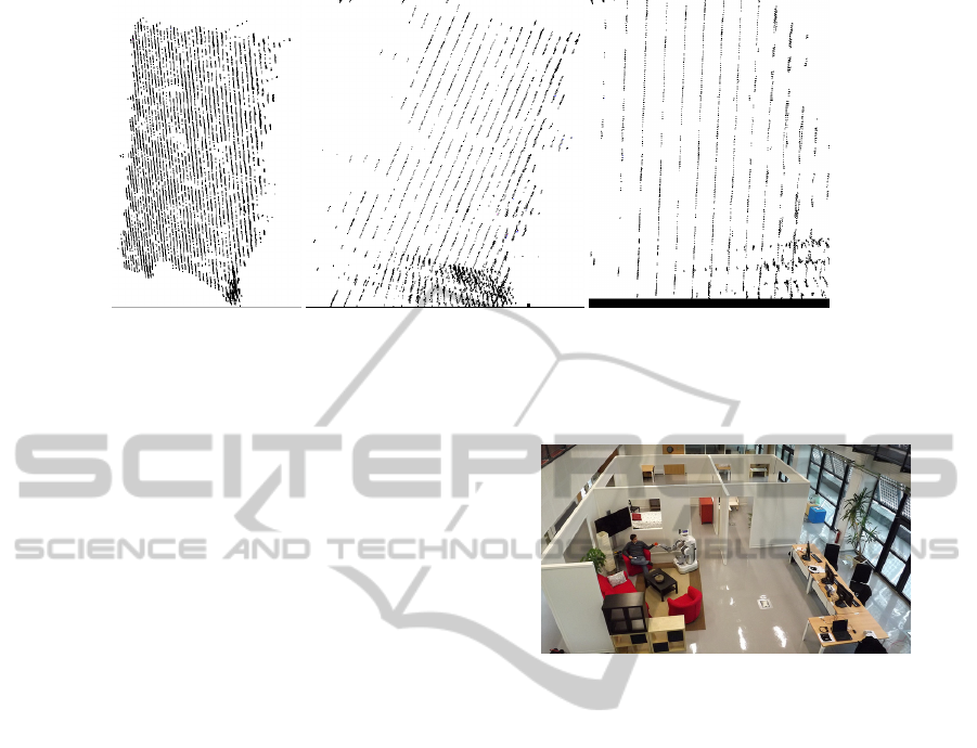
Figure 8: 3D points corresponding for wooden board at different distances from the sensor. 2.5m (left), 4m (middle), 5m
(right) from the sensor.
features with lower memory consummation, as sam-
pling points on planar faces (surfels) or by keeping
just the concave or convex hull polygon of the plane.
4 DISCUSSIONS
As we have seen, all characteristics are correlated and
any choice based on one criterion can influence other
ones. For example if we choose the Kinect for its
high resolution, we have to deal with the problem of
memory space and the time of processing; so it could
be required to downsample data, decreasing the res-
olution. In addition, there is the depth discretization
effect, that makes the built surfacic representation less
accurate. The ToF camera has a good precision but its
narrow FoV makes it unsuitable for large environment
modeling.
In opposite of the two 3D cameras, the tilted LRF
gives the possibility to adjust many parameters as res-
olution and FoV. But the difficulty is that points ac-
quired only on a line do not give information about
the 3D scene structuration. If lines must be accumu-
lated to build a 3D image like the ones acquired by the
Kinect or ToF cameras, it could require a stop-and-go
strategy. But, we want to model the environment on
the fly, i.e. without stopping the robot to acquire data.
We proposed a way to get 3D information from
scan lines without stopping the robot, by transforming
points to the world frame using the successive robot
position, then accumulating lines in a buffer of three
lines used as a sliding window. This buffer could be
larger, but three lines at least are required to estimate
the normal vector on every 3D point; more lines could
improve the estimation, but could prevent from real
time processing. The three-lines buffer is shifted each
time a new line is acquired. The data in the buffer can
be processed by estimating the normal vectors, and
then, by finding the planes by any method. It allows
to accumulate planar surfels instead of building a 3D
image to be processed later.
Figure 9: The apartment.
To evaluate each sensor that could be used on a
robot devoted to the domotic applications, acquisi-
tions have been done inside an simulated flat built in
our experimental room for this reason. The robot has
moved inside and around the apartment (Figure 9).
Figures 10 and 11 present top views of data accu-
mulated during these motions using either the Kinect
or the tilted Hokuyo sensors; the robot has learnt a
map off line, using the Gmap ROS node, so that ac-
quired data are only transformed to be expressed in a
global reference frame, without extra registration pro-
cess. The discretization effect due to the Kinect poor
resolution for far planes, appears clearly.
Figure 12 shows a simulation result on data acqui-
sition with the tilted Hokuyo sensor during the mo-
tion of our robot inside a room. The standard tuning
for the pan scanning gives a 180
◦
range and a 0.25
◦
angular resolution on each line, i.e. 720 3D points ac-
quired at 40Hz (25ms for one scan). The periodic tra-
jectory of twice the 80
◦
is executed in 8 sec, 4 sec for
a complete scan, i.e. two pan scanning are acquired
for one degree for the tilt scanning. The 80
◦
range is
selected from +40
◦
to −40
◦
with respect to the hori-
zontal plane. Data are acquired successively while the
LRF moves either upwards or downwards. Acquired
data are corrected on the fly, so that all points are ex-
pressed in the environment reference frame (defined
ComparisonofActiveSensorsfor3DModelingofIndoorEnvironments
447

when the map has been learnt by the Gmap node), us-
ing the TF and the AMCL ROS nodes to exploit the
odometry data and the robot localization. Each point
is transformed using the interpolated robot position
and laser beam orientation; it can be seen that data
are acquired on-the-fly without adding artefacts
Figure 10: Top view of the point cloud accumulated from
Kinect, while the robot explores the apartment. The trajec-
tory traversed by the robot is in red.
Figure 11: Top view of the point cloud accumulated from
the tilted LRF, while the robot explores the apartment.The
trajectory traversed by the robot is in red.
Figure 12: A point cloud acquired on the fly during a 4m.
robot motion using the HOKUYO sensor.
5 CONCLUSIONS
This paper has presented the evaluation of three 3D
sensors that could be used for the 3D modeling
of large scale indoor environments: a tilted Laser
RangeFinder, a Kinect RGB-D camera and a ToF
camera. We have presented the main characteristics
of each sensor; the more important ones are the field
of view, the maximal range, the angular resolution,
the depth step discretization, the data structure and the
required memory space. Some of these characteristics
can be tuned, some other ones depend on the technol-
ogy: all ones have an influence on the mapping result.
Other characteristics have also an effect on the qual-
ity of acquired data, like intrinsic parameters and the
calibration process for the cameras, that can improve
the sensor precision with few millimeters and filter or
correct some wrong measurements; it is assumed here
that sensors are calibrated off line in an optimal way.
In large environments, the covering zone is one
of the most important factors; a short range and/or
a narrow FoV make a sensor blind or short-sighted,
and oblige us to make a lot of acquisitions to cover
the whole environment by executing many motions,
making the final result more sensitive to localization
errors. In addition to make robot exploration longer,
another consequence is the large amount of data to
store, so the problem of memory space needed to store
all data.
So the two 3d cameras have been rejected because
of their narrow FoV. It remains only the tilted LRF
with its wide FoV, but with some other drawbacks:
(1) it is originally a 2D sensor, so scanning is manda-
tory, and (2) it does not give information about sur-
face appearances (color), even if reflectance data are
made available by some LRF. Considering the scan-
ning problem, a method is proposed to acquire data
without a classical stop-and-go strategy, by using a
sliding window to accumulate lines in a buffer of three
lines and by correcting all points using odometry and
localization data provided by other modules. By this
way, we are able to use the tilted LRF sensor as a 3D
sensor in order to acquire point clouds and process
it in real time, while the robot explores the environ-
ment. In-going works consider texture mapping from
images acquired by cameras embedded on the robot.
REFERENCES
An, S.-Y., Lee, L.-K., and Oh, S.-Y. (2012). Fast incremen-
tal 3d plane extraction from a collection of 2d line
segments for 3d mapping. In Intelligent Robots and
Systems (IROS), 2012 IEEE/RSJ International Con-
ference on, pages 4530 –4537.
ICINCO2013-10thInternationalConferenceonInformaticsinControl,AutomationandRobotics
448

Dellaert, F. and Kaess, M. (2006). Square root sam: Si-
multaneous localization and mapping via square root
information smoothing. The International Journal of
Robotics Research, 25(12):1181–1203.
Douillard, B., Underwood, J., Melkumyan, N., Singh, S.,
Vasudevan, S., Brunner, C., and Quadros, A. (2010).
Hybrid elevation maps: 3d surface models for seg-
mentation. In Intelligent Robots and Systems (IROS),
2010 IEEE/RSJ International Conference on, pages
1532 –1538.
Grisetti, G., Stachniss, C., and Burgard, W. (2007).
Improved techniques for grid mapping with rao-
blackwellized particle filters. Robotics, IEEE Trans-
actions on, 23(1):34–46.
Henry, P., Krainin, M., Herbst, E., Ren, X., and Fox, D.
(2012). RGB-D mapping: Using kinect-style depth
cameras for dense 3D modeling of indoor environ-
ments. International Journal of Robotics Research
(IJRR), 31(5):647–663.
Khoshelham, K. and Elberink, S. O. (2012). Accuracy and
resolution of kinect depth data for indoor mapping ap-
plications. Sensors, 12(2):1437–1454.
Klaess, J., Stueckler, J., and Behnke, S. (2012). Efficient
mobile robot navigation using 3d surfel grid maps.
Robotics; Proceedings of ROBOTIK 2012; 7th Ger-
man Conference on, pages 1 –4.
Lai, K., Bo, L., Ren, X., and Fox, D. (2011). A large-
scale hierarchical multi-view rgb-d object dataset. In
Robotics and Automation (ICRA), 2011 IEEE Interna-
tional Conference on, pages 1817 –1824.
May, S., Droeschel, D., Holz, D., Fuchs, S., Malis,
E., N
¨
uchter, A., and Hertzberg, J. (2009). Three-
dimensional mapping with time-of-flight cameras. J.
Field Robot., 26(11-12):934–965.
Newcombe, R., Izadi, S., Hilliges, O., Molyneaux, D., Kim,
D., Davison, A., Kohli, P., Shotton, J., Hodges, S.,
and Fitzgibbon, A. (2011). Kinectfusion: Real-time
dense surface mapping and tracking. In Proc. IEEE
Int. Symp. on Mixed and Augmented Reality (ISMAR),
Basel (Switzerland).
N
¨
uchter, A. and Hertzberg, J. (2008). Towards seman-
tic maps for mobile robots. Robot. Auton. Syst.,
56(11):915–926.
Rusu, R., Marton, Z., Blodow, N., Holzbach, A., and Beetz,
M. (2009). Model-based and learned semantic object
labeling in 3d point cloud maps of kitchen environ-
ments. In Intelligent Robots and Systems, 2009. IROS
2009. IEEE/RSJ International Conference on, pages
3601 –3608.
Smisek, J., Jancosek, M., and Pajdla, T. (2011). 3d
with kinect. In Computer Vision Workshops (ICCV
Workshops), 2011 IEEE International Conference on,
pages 1154 –1160.
Sturm, J., Engelhard, N., Endres, F., Burgard, W., and Cre-
mers, D. (2012). A benchmark for the evaluation of
rgb-d slam systems. In Intelligent Robots and Systems
(IROS), 2012 IEEE/RSJ International Conference on,
pages 573 –580.
Trevor, A., Rogers, J., and Christensen, H. (2012). Planar
surface slam with 3d and 2d sensors. In Robotics and
Automation (ICRA), 2012 IEEE International Confer-
ence on, pages 3041 –3048.
Wolf, D. and Sukhatme, G. (2008). Semantic mapping us-
ing mobile robots. Robotics, IEEE Transactions on,
24(2):245 –258.
ComparisonofActiveSensorsfor3DModelingofIndoorEnvironments
449
