
Stator Winding Short Circuit Fault Detection based on Uncertainty
Ellipsoid Intersection for Three Phase Induction Motors
Mohammed Obaid Mustafa and George Nikolakopoulos
Control Engineering Group, Division of Systems and interaction, Department of Computer Science,
Electrical and Space Engineering, Lule˚a University of Technology, SE- 97187 Lule˚a, Sweden
Keywords:
Three Phase Induction Motor, Fault Detection and Diagnosis, Set Membership Identification, Uncertainty
Ellipsoid Intersection, Geometrical Analysis.
Abstract:
In this article a fault detection scheme for different percentage of stator winding short circuit in one phase of
three phase induction motors is presented. In the examined case, the induction motor in the faulty and healthy
case has been transformed in the two phase (q− d) model. The model has been identified by the utilization of
a Least Squares Set Membership Identification (SMI) algorithm, where additional to the identified parameters,
confidence intervals can be also calculated, based on a priori knowledge for the corrupting measurement
noise. The identified confidence intervals in an µ–dimensional space can be represented as hyper–ellipsoids
having as a center the identified parameters’ vector. The novelty of this article stems from the proposal of a
fast and geometrical based scheme, which relies on the calculation of the distance among centers of hyper–
ellipsoids and the corresponding intersection in each iteration of the identification procedure. Detailed analysis
of the proposed fault detection strategy, as also extended simulation results are being presented that prove the
efficiency of the suggested scheme.
NOMENCLATURE
V
qs
, V
ds
: Stator voltages Quadrature frame (V)
i
qs
, i
ds
: Stator currents Quadrature frame (A)
r
s
, r
r
: Resistance of stator’s and rotor’s winding (Ohm)
L
s
, L
r
: Stator’s and rotor’s self inductance (Henry)
L
m
: Mutual inductance (Henry)
ω
r
: Rotor’s angular speed (rad/sec)
ω
m
: Rotor’s speed (mechanical) (rad/sec)
ω
s
: Supply angular frequency (rad/sec)
P : No. of poles pairs
J : Moment of inertia (Kg· m
2
)
T
L
: Load torque (Nm)
T
e
: Electromagnetic torque (Nm)
q : Quadrature axis frame
d : Direct axis frame
s : Stator quantities
r : Stator quantities
1 INTRODUCTION
Three phase induction motors are very important in
different applications in industrial and power sys-
tems (F. Jawad, 2009) as it is commonly known that
induction motors have good properties such as highly
reliability, require low maintenance, and have high
efficiency. Therefore, the condition monitoring of
these electrical machines has received considerable
attention in recent years as fault detection and diag-
nosis are very important to reduce the maintenance
cast and prevent downtimes for electrical drive sys-
tems (B. Mirafzal, 2006).
Induction motors have many type of faults, while
some of these fault happen in the stator or in the ro-
tor, such as short circuit in stator winding, broken ro-
tor bar, and bearing faults (Nandi and Toliyat, 2005).
Stator winding consists of coils of insulated copper
wire placed in the stator slots, while the stator wind-
ing faults start due to the insulation breakdown be-
tween two adjacent turns in a coil for the same phase;
this fault is usually called a turn–to–turn fault or inter-
turn short circuit. Therefore, this type of fault is very
serious as it will produce an extra heat, and it will cre-
ate an imbalance in the magnetic filed of the machine.
In fact, the majority of these defects are due to a com-
bination of various stresses acting on the stator, which
can be classified into thermal, electrical, mechanical,
and environmental factors.
Until now, various scientific methods have been
proposed in the field of fault detection and diagno-
206
Obaid Mustafa M. and Nikolakopoulos G..
Stator Winding Short Circuit Fault Detection based on Uncertainty Ellipsoid Intersection for Three Phase Induction Motors.
DOI: 10.5220/0004476802060212
In Proceedings of the 10th International Conference on Informatics in Control, Automation and Robotics (ICINCO-2013), pages 206-212
ISBN: 978-989-8565-70-9
Copyright
c
2013 SCITEPRESS (Science and Technology Publications, Lda.)

sis for induction motors such as: a) Artificial Neu-
ral Networks (Gaeid and Mohamed, 2010), b) Fast
Fourier Transform (Bachi et al., 2006), c) Time Step
Coupled Finite Element-State Space (Gaeid and Mo-
hamed, 2010), d) Motor Current Signature Analy-
sis (Aydin et al., 2011), e) Wavelets, and Complex
Park Vectors (Gaeid and Mohamed, 2010).
All of these methods base their operation on spec-
tral analysis of stator currents, stator voltages, and
electromagnetic torque (Aydin et al., 2011), while
are able to provide a faster detection and identifica-
tion of the fault, but will lead to incorrect conclu-
sions in some cases, such as low load conditions, in
transient situations or in perturbed environments (i.e.
fluctuating load torque and unideal supply). From an-
other point of view Independent Component Analy-
sis (ICA) and Support Vector Machines (SVMs) have
been applied to detect and diagnose of induction mo-
tor faults (Widodo et al., 2007; A. Widodo, 2008)
as alternative approaches to the previous mentioned
cases.
The novelty and the main scientific contribution
of this article stems from: a) the combination of
the SM–identification technique for calculating recur-
sively the motor parameters and the corresponding
uncertainty boundsbasedon theassumed noise levels,
with b) the proposal of a fault detection scheme based
on fundamental geometrical properties of the calcu-
lated parameter bounding uncertainty. More analyti-
cally, in this article the problem of fault detection is
transformed to the geometrical problem of represent-
ing uncertainty into µ–dimensional hyper–ellipsoid
spaces and examining basic properties of the result-
ing µ–dimensional spaces, such as center of ellipsoid,
ellipsoidal intersection, and distance from the centers.
The proposed scheme has a low complexity and as it
is going to be presented in the sequel, it can be di-
rectly transferred to real life implementations.
The rest of the article is being structured as it fol-
lows. In Section 2 the model derivation and simpli-
fication, for the healthy and the faulty cases is being
derived. In Section 3 the SMI scheme is being pre-
sented, followed by the proposed fault conditioning
framework in Section 4. Section 5 contains multiple
simulation results that prove the efficacy of the pro-
posed methodology, while the conclusions are drawn
in the last Section 6.
2 INDUCTION MOTOR
MODELING
2.1 Healthy Case
The state space form for the three phase induction
motor can be represented as it follows: (Vas, 1992;
Mustafa et al., 2012b)
di
qs
dt
di
ds
dt
di
qr
dt
di
dr
dt
= A
i
qs
i
ds
i
qr
i
dr
+ B
V
qs
V
ds
0
0
(1)
where:
A =
1
δ
−L
r
r
s
0 L
m
r
s
0
0 −L
r
r
s
0 L
m
r
s
L
m
r
r
0 −L
s
r
r
w
r
δ
0 L
m
r
r
−w
r
δ −L
s
r
r
B =
1
δ
L
r
0 −L
m
0
0 L
r
0 −L
m
−L
m
0 Ł
s
0
0 −L
m
0 L
s
with δ defined as:
δ = L
s
L
r
− Lm
2
while the motor’s torque and angular speed, in case
that the fraction is being neglected, is denoted as:
T
e
=
3
2
P L
m
[i
qs
i
dr
− i
qr
i
ds
]
J
dω
m
dt
= T
e
− T
L
2.2 Stator Winding Short Circuit
Modeling
The focus of this research effort is on the stator faults
during short circuit between stator winding, which
happen in one phase of the motor. In the examined
case all the stator parameters are considered to be
identical when short circuit happens in the winding
of the three phase induction motor, while both sta-
tor’s resistance and inductance, as also the mutual in-
ductances between stator and rotor will be directly
affected. In the case of such a fault, the modified
(faulty) versions of the matrices A and B in equa-
tion (1), will be changed to A
∗
and B
∗
and become
as:
A
∗
= −R
∗
f
L
∗
f
−1
B
∗
= L
∗
f
−1
StatorWindingShortCircuitFaultDetectionbasedonUncertaintyEllipsoidIntersectionforThreePhaseInductionMotors
207

while the inductance matrix in the faulty case will be-
come as (Chen and Zivanovic, 2009):
L
∗
f
=
L
11
0 L
14
0
0 L
22
0 L
25
L
41
0 L
44
0
0 L
52
0 L
55
The elements of L
∗
f
are being defined as (Chen and
Zivanovic, 2009):
L
11
=
1
3
(g
as
+ 1)L
s
+
1
9
(2g
as
+ 1)
2
L
s
L
14
= L
41
=
1
3
(g
as
+ 1)L
m
, L
22
= L
s
+ L
m
L
25
= L
52
= L
m
, L
44
= L
55
= L
r
+ L
m
and
R
f
∗
=
r
∗
0 0 0
0 r
s
0 0
0 −ω
r
/ω
s
L
∗
m
rr −ω
s
/ω
s
L
r
ω
r
/ω
s
L
∗
m
0 ω
r
/ω
s
L
r
rr
with:
r
∗
= r
s
· r
s11
L
∗
m
= L
m
· L
14
r
s11
=
1
3
(2g
as
+ 1)
g
sa
is the percentage of the remaining un–shorted sta-
tor windings in stator phase a (Chen and Zivanovic,
2009). These models will be utilized in the following
simulation studies for simulating the healthy and the
faulty induction motor operations.
3 SET MEMBERSHIP
IDENTIFICATION
The method of Weighted Recursive Least Squares
Set Membership Identification has been utilized ef-
ficiently in the fault detection and diagnosis in both
cases of broken rotor bar and short circuit in stator
winding for the three phase induction motor (Mustafa
et al., 2012b). The objective of the Set Membership
Identification technique (SMI) is the determination of
a feasible recursively identified uncertainty parame-
ter set that contains the nominal parameter vector and
is consistent with a linearly parameterizable model,
the measurement data and the a priori known bounded
noise–error. In the SMI approach, instead of identify-
ing directly the unknown parameter, the correspond-
ing uncertainty bounds that include the nominal value
are being calculated instead, while in each iteration
the center of the uncertainty interval is equal with the
current value of the identified parameter.
The q−d model of the induction motor is being trans-
formed into an ARMA system, which can be de-
scribed in a generic form as:
i
j
(t) = Φ
j
(t)
T
ˆ
θ
j
(t) +e
j
(t) (2)
where
ˆ
θ
j
(t) is the identified parameter vector set and
the subindex j represents the current set that can be
selected as one from: [qs, ds]. Moreover θ
j
(t) con-
tains the corresponding coefficients of the selected
ARMA model and can be defined in the general case
as:
ˆ
θ
j
(t) = [F
j,1
(t),.. ., F
n,1
(t), T
j,1
(t),.. .,T
m,1
(t)] (3)
the regression vector Φ
j
(t) is formulated as:
Φ
j
(t) = [−y
j
(t − 1), ... ,−y
j
(t −n), .. . ,
u
j
(t +m− n−1),. .. ,u
j
(t −n)]
and the adopted ARMA model representation of the
transfer function of induction motor will be denoted
as:
i
j
V
j
=
T
j,1
z
m−1
+ T
j,2
z
m−2
+ ....... + T
j,m
z
n
+ F
j,1
z
n−1
+ ....... + F
j,n
The identified parameters presented in equation (3),
are directly related with the motor parameters (resis-
tance and inductance of the stator and rotor), while
more details about the mathematical relationship be-
tween these parameters of induction motor in the
healthy case could be found in (Mustafa et al., 2012b;
Mustafa et al., 2012a), where n, m ∈ Z
+
are the orders
of the numeratorand denominatorforeach considered
transfer function and µ = n + m.
In equation (2) the additive measurement noise is
assumed to be bounded by γ
j
∈ ℜ
+
as:
γ
j
||e
j
(t)||
2
≤ 1,∀ t
The core of the SMI technique is based on the
Weighted Recursive Least Squares (WRLS) with a
forgetting factor (λ) for identifying the
ˆ
θ
j
motor’s
parameters and can be formulated by the following
double recursions (Guastafsson, 2001) in the sample
instance t and for the MIMO case j as:
ˆ
θ
j
(t) =
ˆ
θ
j
(t −1) + K
j
(t)(y
j
(t) −Φ
T
j
(t)θ
j
(t −1))
K
j
(t) = P
j
(t)Φ
j
(t) = P
j
(t − 1)Φ
j
(t)(λ
+Φ
T
j
(t)P
j
(t −1)φ
j
(t))
−1
P
j
(t) = (I − K
j
(t) Φ
T
j
(t))P
j
(t − 1)/λ
e
j
(t) = y
j
(t) −Φ
T
j
(t)θ
j
(t −1)
G
j
(t) = Φ
T
j
(t)P
j
(t −1)Φ(t)
In the SMI approach the uncertainty description is
evolving with the time, as the better the knowledge of
the parameters is, the smaller these bounds are, while
ICINCO2013-10thInternationalConferenceonInformaticsinControl,AutomationandRobotics
208
as a fundamental property in SMI (Deller, 1989a),
these bounds cannot be less than the assumed or com-
puted range of noise corrupting the measurements.
For calculating the upper and lower boundary of the
identified parameters, the uncertainty bounds σ
j
(t),
should be computed in every iteration and will be-
come as:
σ
j
(t) =
q
diag(P
j
(t)) (4)
with the covariance matrix denoted as
C
j
(t) = P
j
(t)
−1
and P positive definite (Deller,
1989b; Le et al., 2008).
4 FAULT DETECTION
CONDITIONING
Based on the SMI scheme, presented in Section 3 and
on the uncertainty bounds in Eq. (4), for every iden-
tified parameter a hyper ellipsoid can be defined hav-
ing as center the current values of the identified pa-
rameters from Eq. (2). In the following analysis, the
notation for these identified values will be simplified
to (Kurzhanskiy and Varaiya, 2008):
ˆ
θ
j
(t) = [q
1
(t) ... q
n+m
(t)] (5)
and the ellipsoid will be considered as the set ε(q, σ)
in R
n+m
with center q and shape matrix σ as:
ε(q,σ) = {x ∈ R
n
| h(x− q),σ
−1
(x− q)i ≤ 1} (6)
where σ is positive definite, hx,σxi > 0 for all nonzero
x ∈ R
n+m
and with h·,·i to denote the inner product.
The support function of a set X ⊆ R
n+m
and the sup-
port function of the ellipsoid in Eq. (6) will become
as:
ρ(l| X) = sup
x∈X
hx,li (7)
ρ(l| ε(q,σ)) = hl,qi + (hl, σli)
1
2
(8)
Therefore, it is useful to give an alternative definition
of an ellipsoid using the expression Eq. (8) as:
ε(q,σ) = {x ∈ R
n
| hl, xi ≤ hl, qi+ (9)
hl,σli
1
2
} for all l ∈ R
n+m
where σ is positive semidefinite, hx,σxi ≥ 0 for all
nonzero x ∈ R
n+m
(Kurzhanskiy and Varaiya, 2008).
Given two hyper–ellipsoids ε(q
1
,σ
1
) and ε(q
2
,σ
2
),
the distance between them is:
dist(ε(q
1
,σ
1
),ε(q
1
,σ
1
)) = max
hl,li=1
(−ρ(−l|ε(q
1
,σ
1
))
−(ρ(l|ε(q
2
,σ
2
))
= max
hl,li=1
(hl,q
1
i −(hl,σ
1
li)
1
2
−hl,q
2
i −(hl,σ
2
li)
1
2
)
The intersection between two ellipsoids can be also
transformed to a distance problem, which can be
cast as QuadraticallyConstrained QuadraticProgram-
ming (QCQP) problem as: (Kurzhanskiy and Varaiya,
2008):
dist(ε(q
o
,σ
o
),ε(q
f
,σ
f
)) = minh(x
o
− y
f
),(x
o
− y
f
)i (10)
subject to
h(q
o
− x
o
),σ
o
−1
(q
o
− x
o
)i ≤ 1
h(q
f
− y
f
),σ
f
−1
(q
f
− y
f
)i ≤ 1
with x
o
, x
f
,y
o
, y
f
∈ ℜ
n
points on the hyper–ellipsoids
surfaces for the healthy and the faulty case respec-
tively, with the following conditions:
dist(ε(q
o
,σ
o
),ε(q
f
,σ
f
))
> 0: no common points
= 0: one common point
< 0: ellipsoids intersect
The proposed fault detection scheme is based only on
geometrical properties of the structured parameters’
uncertainty and more specifically is based on the on-
line and fast computation of the recursively computed
centers of ellipsoids and the corresponding distances
between the centers. In all the performed geometri-
cal calculations two ellipsoids are being considered:
a) the nominal and converged ellipsoid of the error
free identified motor model, denoted as ε
o
, and b) the
iteratively computed uncertainty ellipsoid ε after pa-
rameters’ convergence and the definition of the previ-
ous nominal ellipsoid ε
o
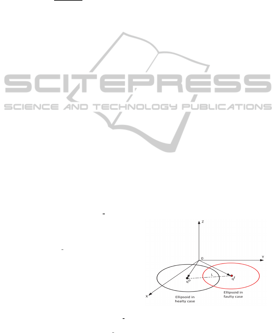
. In Figure 1, two illustrative
instances representing bounding ellipsoid uncertainty
from the case of the healthy and faulty motor’s opera-
tion are presentedin a projectioninto a 2–dimensional
frame, to allow a straight forward and comprehensive
geometrical representation, without any loss of gener-
ality.
Figure 1: Projection of ellipsoid intersection in X-Y plane.
In this Figure, the general case of intersection and
shifting of centers between the two ellipsoids has been
StatorWindingShortCircuitFaultDetectionbasedonUncertaintyEllipsoidIntersectionforThreePhaseInductionMotors
209
presented also. while the distance L(t) ∈ ℜ
n+m
be-
tween the centers has been denoted as:
L(t) = [(q
o
1
− q
f
1
)
2
+ (q
o
2
− q
f
2
)
2
+ .... +(q
o
n+m
− q
f
n+m
)
2
]
1
2
In the case of a stator winding short circuit, the val-
ues of the identified parameters and the correspond-
ing uncertainty bounds will drift from their converged
values, which has a direct effect and change on the
center and the direction of the bounding uncertainty
µ–dimensional hyper ellipsoids at each sample time
(iteration) and thus a fault detection scheme can be
directly established based on a straight forward in-
spection of geometrical properties for the bounding
ellipsoids as it is being presented in Figure 2.
The initialization phase of the proposed fault de-
tection algorithm assumes that the SMI scheme has
converged in identifying the nominal parameters of
the adopted model for the induction motor and thus
the corresponding bounds on the parametric uncer-
tainty intervals have been also converged. In the se-
quel the SMI scheme continuous the online identifi-
cation of the parameters, while constructing the se-
quential bounding uncertainty µ–D ellipsoids. Upon a
short circuit fault the upcoming online calculated µ–D
bounding ellipsoids will present a change in their vol-
ume and an intersection will occur with the nominal
defined converged µ–D ellipsoid volume, which is a
direct indication of a fault. In case that there is no in-
tersection the fault detection algorithm will continue
to operate, while checking the existence of such an in-
tersection. The parametric drift after the event of the
fault will also producea corresponding drift on the el-
lipsoid’s center and thus the distance among ellipsoid
centers are being also tracked by calculating the value
of L. In case that this distance is not close to 0, then in
combination with the ellipsoid intersection, these two
conditions will lead to a fault detection instance.
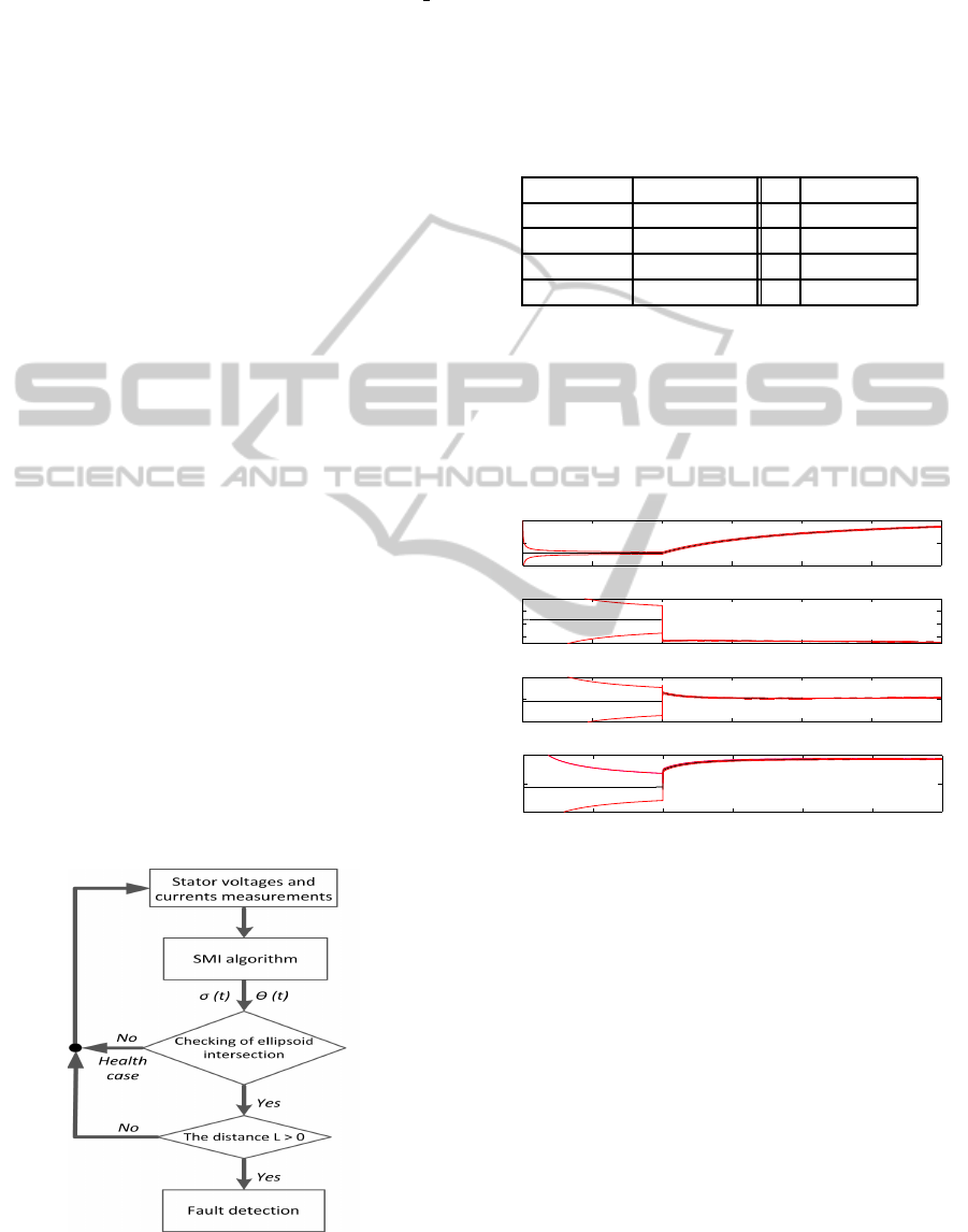
Figure 2: Flowchart of fault detection conditions.
5 SIMULATION RESULTS
The suggested scheme for fault detection is being
evaluated on a model of three phase induction motor
having the parameters depicted in Table 1. The pre-
sented results examine the application of the proposed
geometrical analysis on two cases of short circuit sta-
tor winding with 2%, and 5% faults.
Table 1: Induction Motor Parameters.
Pole Numbers 4 r
s
0.0616 per unit
Input Voltage 240V r
r
0.0753 per unit
Frequency 50Hz J 0.00155 Kg.m
L
r
0.019 per unit L
s
0.019 per unit
L
m
0.01833 per unit
The identified parameters and uncertainty bounds in
the healthy and faulty case of 2% short circuit are pre-
sented in figures 3 and 4, where the fault occurred
at the 10
5
sample time instance and the change in
the motor parameters are obvious because of this sta-
tor fault. In Figure 5 the iterative evolution of
0 0.5 1 1.5 2 2.5 3
x 10
5
8
9
10
T
qs,1
Short circut
0 0.5 1 1.5 2 2.5 3
x 10
5
−10
0
10
T
qs,2
0 0.5 1 1.5 2 2.5 3
x 10
5
−10
0
10
T
qs,3
0 0.5 1 1.5 2 2.5 3
x 10
5
−5
0
5
Sample time
T
qs,4
Figure 3: SMI based identified parameters for T
qs,i
and cor-
responding uncertainty bounds.
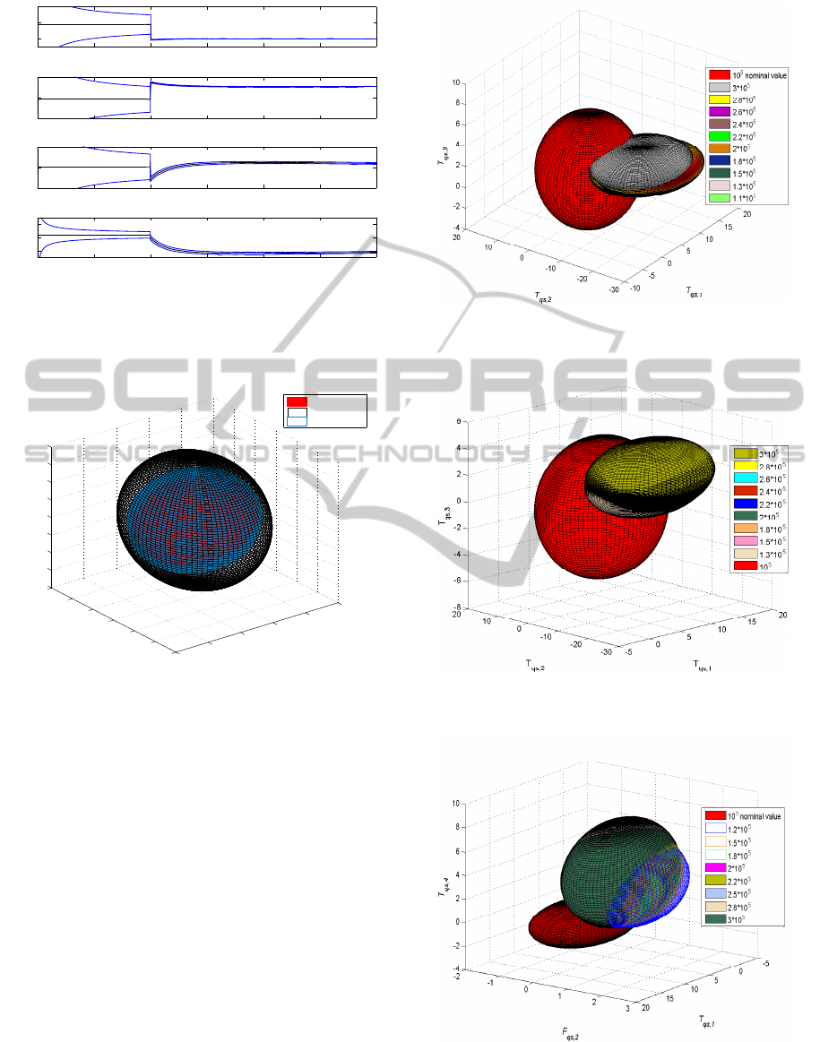
the ellipsoid volume (bounding uncertainty), during
identification in the healthy case and for a projection
based on the selected triplet (center of ellipsoid) of
T
qs,1
, T
qs,2
, T
qs,3
is being presented at different time
indexes. From the obtained results it can be observed
that the ellipsoids volume is monotonically decreased
without any intersections taking place at the different
time instances. This result and the presented bound-
ing uncertainty are in fully accordancewith the results
presented in Figure 5.
In Figures 6 and 7 the uncertainty ellipsoids in the
nominal case and after the occurrence of the fault at
different sample times for the same case of consider-
ing the triplet of T
qs,1
, T
qs,2
, T
qs,3
identified parame-
ters, for both the cases of 2% and 5% of stator wind-
ICINCO2013-10thInternationalConferenceonInformaticsinControl,AutomationandRobotics
210
0 0.5 1 1.5 2 2.5 3
x 10
5
−2
0
2
F
qs,1
0 0.5 1 1.5 2 2.5 3
x 10
5
−2
0
2
F
qs,2
0 0.5 1 1.5 2 2.5 3
x 10
5
−0.5
0
0.5
F
qs,3
0 0.5 1 1.5 2 2.5 3
x 10
5
−0.1
0
0.1
Sample time
F
qs,4
Figure 4: SMI based identified parameters for F
qs,i
and cor-
responding uncertainty bounds.
ing short circuit correspondingly are being presented.
−5
0
5
10
15
20
−30
−20
−10
0
10
20
30
−0.06
−0.04
−0.02
0
0.02
0.04
0.06
0.08
0.1
T
qs,1
T
qs,2
T
qs,3
@10
5
nominal case
@20000
@50000
Figure 5: Ellipsoid in healthy case at different sample time.
The centers of ellipsoids and the corresponding uncer-
tainty bounds will drift from their converged healthy
value at each sample time. The ellipsoids intersec-
tion between the nominal case and the faulty case has
been easily tracked in the proposed geometrical ap-
proach to fault detection, while this drift will evolve
after fault’s occurrence. In Figure 8 it is also pre-
sented the geometrical drift in the bounding ellipsoids
and the corresponding intersection, for the case where
a different triplet have been considered of a center
T
qs,1
, F
qs,2
, T
qs,4
for the case of 2% short circuit.
Finally the distance L in the case that the whole
(µ)-dimensional hyper ellipsoid is being considered
during the healthy operation and after the fault oc-
currence, for the cases of 2%, and 5% short circuit
are being presented in Figure 10. As it can be pre-
sented, the hyper distance will be increased after the
fault occurrence and it will become greater than zero
as shown in figures (9).
Figure 6: Ellipsoid interaction between healthy and faulty
case (2% short circuit).
Figure 7: Ellipsoid interaction between healthy and faulty
case (5% short circuit).
Figure 8: Ellipsoid interaction between healthy and faulty
case (2% short circuit).
StatorWindingShortCircuitFaultDetectionbasedonUncertaintyEllipsoidIntersectionforThreePhaseInductionMotors
211
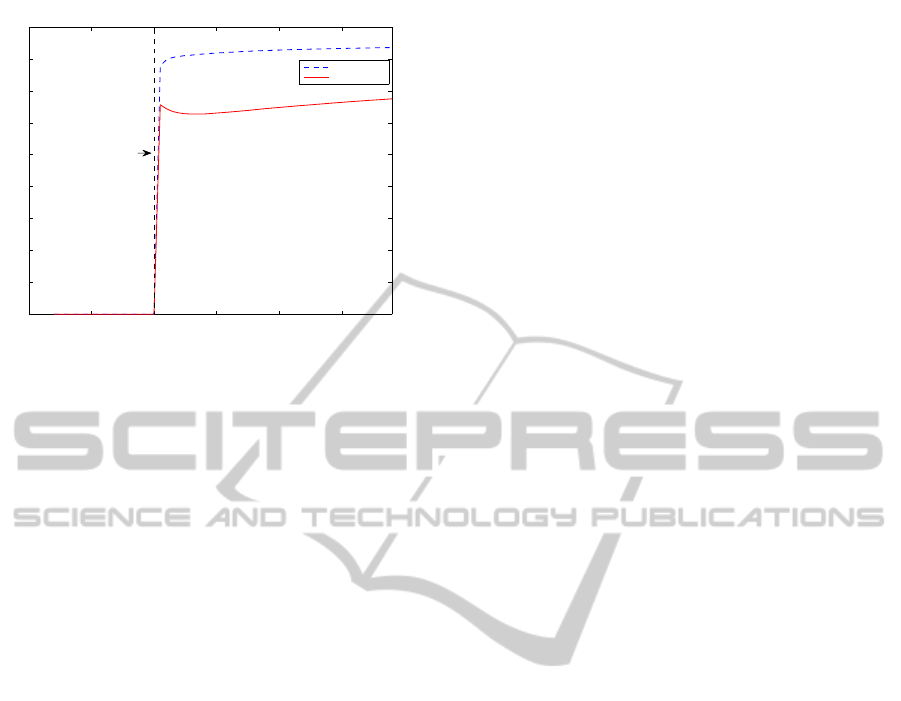
0 0.5 1 1.5 2 2.5
x 10
5
0
2
4
6
8
10
12
14
16
18
Sample time
Distance L
5% short circuit
2% short circuit
Fault
occurrence
Figure 9: The distance L in healthy and faulty case (2%, 5%
short circuit).
6 CONCLUSIONS
In this article a fault detection scheme for different
percentageof stator winding short circuit in one phase
of three phase induction motors is presented. The mo-
tor’s model was identified by the utilization of a Least
Squares Set Membership Identification (SMI) algo-
rithm, where additional to the identified parameters,
confidence intervals have been calculated, These in-
tervals in an µ–dimensional space can be represented
as hyper–ellipsoids having as a center the identified
parameters’ vector and thus a geometrical fault detec-
tion scheme has been proposed, which relied on the
calculation of the distance among centers of hyper–
ellipsoids and the corresponding intersections. Ex-
tended simulation results were presented that proven
the efficiency of the suggested scheme.
REFERENCES
A. Widodo, a. B. Y. (2008). Wavelet support vector ma-
chine for induction machine fault diagnosis based on
transient current signal. Expert Systems with Applica-
tions, 35:307316.
Aydin, I., Karakose, M., and Aki, E. (2011). A new
method for early fault detection and diagnosis of bro-
ken rotor bars. Energy Conversion and Management,
52(4):1790–1799.
B. Mirafzal, N. A. O. D. (2006). On innovative methods of
induction motor interturn and broken-bar fault diag-
nostics. IEEE TRANSACTIONS ON INDUSTRY AP-
PLICATIONS, 42(2).
Bachi, S., Tnani, S., Trigeassou, J., and Champenois,
G. (2006). Diagnosis by parameter estimation of
stator and rotor faults occurring in induction ma-
chines. IEEE Transactions on Industrial Electronics,
53(3):963–973.
Chen, S. and Zivanovic, R. (2009). Modelling and sim-
ulation of stator and rotor fault conditions in induc-
tion machines for testing fault diagnostic techniques.
European Transactions On Electrical Power, 20:611–
629.
Deller, J. (1989a). Set membership identification in digital
signal processing. IEEE ASSP Magazine, 6(4):4–20.
Deller, J. R. (1989b). Set membership identification in dig-
ital signal processing. IEEE ASSP Magazine, 6(4):4–
20.
F. Jawad, O. M. (2009). Different indexes for eccentricity
faults diagnosis in three-phase squirrel-cage induction
motors a review. Mechanical Sustem and Signal Pro-
cessing, 19:213.
Gaeid, K. S. and Mohamed, H. A. F. (2010). Bibliogra-
phy on induction motors faults detection and diagno-
sis. Australian Journal of Basic and Applied Sciences,
4(2):227–246.
Guastafsson, F. (Sep.2001). Adaptive Filtering and Change
Detection.
Kurzhanskiy, A. A. and Varaiya, P. (2008). Ellipsoidal tool-
box manual.
Le, K., Huang, Z., Moon, C., and Tzes, A. (2008). Fault
detection based on orthotopic set membership iden-
tification for robot manipulators. Proceedings of the
17th World Congress The International Federation of
Automatic Control , Seoul, Korea,2008, pages 7344–
7349.
Mustafa, M. O., Nikolakopoulos, G., and Guastafsson, T.
(2012a). Stator winding short circuit fault detec-
tion based on set membership identification for three
phase induction motors. Proceedings of IEEE, 20th
Mediterranean Conference on Control and Automa-
tion, MED12, pages 290–296.
Mustafa, M. O., Nikolakopoulos, G., and Gustafsson, T.
(2012b). A fault diagnosis scheme for three phase
induction motors based on uncertainty bounds. Pro-
ceedings Of The 38th Annual Conference of the IEEE
Industrial Electronics Society IECON, pages 1606–
1611.
Nandi, S. and Toliyat, H. (2005). Condition monitoring and
fault diagnosis of electrical machines-a review. IEEE
Transactions on Energy Conversion, 20(4):719–729.
Vas, P. (1992). Electrical Machines and Drives.
Widodo, A., Yang, B. S., and Han, T. (2007). Combination
of independent component analysis and support vector
machines for intelligent faults diagnosis of induction
motors. Expert Systems with Applications, 32:299–
312.
ICINCO2013-10thInternationalConferenceonInformaticsinControl,AutomationandRobotics
212
