
Application Engineering for Embedded Systems
Transforming SysML Specification to Simulink within a Product-Line
based Approach
Vanderson H. Fragal, Rogério F. Silva, Itana M. S. Gimenes and Edson A. Oliveira Júnior
Department of Informatics-DIN, Universidade Estadual de Maringá-UEM, Maringá-PR, Brazil
Keywords: Software Product Line, SysML, Simulink, Unmanned Aerial Vehicle, Model Transformation.
Abstract: The evolution of hardware platforms has transferred a great amount of functionality to embedded software,
thus increasing its complexity. Model Driven Engineering (MDE) and Software Product Line (SPL) can
enhance the development of complex embedded systems by using different specification languages
according to the abstraction levels and controlling variability across development. The SyMPLES approach
allows the creation of SysML-based SPLs. It includes two SysML extensions, created by means of the UML
profiling mechanism both to express SPL variability concepts and to associate SysML blocks to the main
classes of functional blocks. This paper presents the transformation process from SysML to Simulink
models. SysML models, created in the SPL application engineering activity of SyMPLES, are used to
generate functional blocks and state machines in Simulink. An application example was developed for one
subsystem of an autopilot board used in Unmanned Aerial Vehicles, named Yapa 2 of Paparazzi project,
which was studied into the context of National Institute of Science and Technology for Safety Critical
Embedded Systems (INCT-SEC).
1 INTRODUCTION
Embedded systems are applications for processing
embedded information in a larger product which is
not usually directly visible to users (Marwedel
2010). The increased computational power of
hardware platforms has led to a fast growth of
embedded software over the last decades mainly due
to the transfer of more functionality to software
(Burch et al. 2001). As a consequence, embedded
systems became larger and more complex, thus more
demanding in terms of software engineering
techniques. The Software Product Line (SPL)
approach (Linden et al., 2007) has been successfully
applied to embedded system (Polzer et al., 2009;
Fragal et al., 2011; Braga et al., 2011).
The Model Driven Engineering (MDE) approach
supports the generation of applications by means of
model transformation, which may be at the same or
different abstraction levels (Czarnecki and Helsen,
2003). During development, various modeling
languages are used to represent the required
abstraction levels. For example, UML/SysML
languages are used to represent higher abstraction
level models (Burch et al., 2001; Brisolara, 2007),
while Simulink (Simulink, 1994) is used to represent
lower abstraction level models (Polzer et al. 2009;
Pastor et al. 2006).
Simulink is a tool used in the development of
embedded systems that represents more than 50% of
the market (Ebert and Jones, 2009). Functional
blocks based on libraries are used to represent
behavior and specific functions which are used as
input to generate C code with Simulink Coder (or
Real-Time Workshop) plug-in (Simulink Coder
2012). There are some approaches that describes
SPL based on Simulink (Pastor et al., 2006; Steiner,
2012). However, they need to add control blocks in
the Simulink model to specify variability which
increases the complexity of product specific models.
Thus, there is a need to represent variability of
SPL at a higher abstraction level. The management
of variability at higher abstraction level models
enables the configuration of products in a top-down
development without adding complexity to lower
abstraction level models.
Systems Modelling Language (SysML) (SysML
2008) is a language for specification of embedded
systems used in the Object-Oriented Systems
94
H. Fragal V., F. Silva R., M. S. Gimenes I. and A. Oliveira Júnior E..
Application Engineering for Embedded Systems - Transforming SysML Specification to Simulink within a Product-Line based Approach.
DOI: 10.5220/0004402600940101
In Proceedings of the 15th International Conference on Enterprise Information Systems (ICEIS-2013), pages 94-101
ISBN: 978-989-8565-60-0
Copyright
c
2013 SCITEPRESS (Science and Technology Publications, Lda.)
Engineering Method (OOSEM) (Lykins 2000). This
method supports the SysML specification of
embedded systems from initial requirements
elicitation, analysis and design through the
integration between hardware and software,
validation and testing.
SysML-based Product Line Approach for
Embedded Systems (SyMPLES) (Silva 2012) is
based on OOSEM. It supports the creation of
SysML-based artifacts with variability management
mechanisms.
This paper presents the process used in the
SyMPLES application engineering activity to
transform SysML models to Simulink ones. The
process has 3 activities: (i) generate the SPL
product; (ii) execute an intermediary ATLAS
Transformation Language (ATL) (Obeo 2006)
transformation; and (iii) create a Matlab script using
both Simulink and Stateflow Application
Programming Interfaces (API).
An application example of the transformation
process was carried out in order to design a part of a
flight controller for an autopilot board named Yapa
2 of the Paparazzi project (YAPA 2011).
This paper is organized as follows: Section 2
presents a background summary; Section 3 presents
the transformation process approach and its
activities; Section 4 presents an application example
of the transformation process for the Yapa 2 board.
Section 5 presents discussion and related works; and
Section 6 presents conclusions and future work.
2 BACKGROUND
Important concepts related to the application of the
SyMPLES approach are presented in this section.
SyMPLES consists of two SysML extensions
named SyMPLES Profile for Representation of
Variability (SyMPLES-ProfileVar) and SyMPLES
Profile for Functional Blocks (SyMPLES-
ProfileFB). SyMPLES also consists of two
processes that use these extensions, named
SyMPLES Process for Product Lines (SyMPLES-
ProcessPL) and SyMPLES Process for Identification
of Variabilities (SyMPLES-ProcessVar).
SyMPLES-ProfileVar is based on the UML
profile defined in the SMarty approach (Oliveira et
al. 2010). SyMPLES-ProfileFB is based on a set of
stereotypes that represents the main classes of
functional blocks, which aims at representing the
behavior associated with standard SysML blocks.
Using Model Driven Engineering (MDE)
techniques, SyMPLES-ProfileFB stereotypes can be
mapped and used to generate functional blocks. A
SysML model, created by a SyMPLES SPL
configuration, can be transformed to a Simulink
model, including functional blocks and state
machines, at a lower abstraction level, which can
then generate code.
In addition to the SysML extensions to represent
variability, SyMPLES defines two processes that use
such extensions for supporting the specification of a
SysML-based SPL. SyMPLES-ProcessPL defines a
set of activities and guidelines for guiding the user in
creating the SPL artifacts from the use cases
definition and requirements structuring phase to the
analysis and design phases; and SyMPLES-
ProcessVar which is concurrently executed with the
first process and contains a set of activities and
guidelines for supporting the user in the
identification, definition and representation of
variability, as well as the SPL product configuration.
In this paper, we use the SyMPLES-ProfileFB
that is composed of a group of stereotypes for
mapping functional blocks and providing additional
semantics to SysML blocks. Thus, it is possible to
associate a certain type of behavior to a standard
SysML block to facilitate the specification of
embedded systems (Silva 2012).
The models represented in SysML that use
SyMPLES-ProfileFB and SyMPLES-ProfileVar are
used as input to the SPL application engineering
activity. Artifacts generated in this activity can be
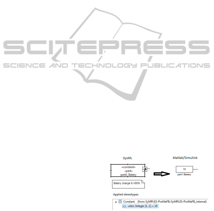
transformed to Simulink models. For example, the
SyMPLES-ProfileFB stereotype <<constant>> was
added to the attribute value. An initial value can be
linked to that stereotype and mapped together to a
functional block as a parameter. Figure 1 shows an
example of a SysML part block in an internal block
diagram. This part represents a battery charge sensor
mapped to a Simulink functional block.
Figure 1: Example of SysML element with a SyMPLES-
ProfileFB stereotype.
ApplicationEngineeringforEmbeddedSystems-TransformingSysMLSpecificationtoSimulinkwithinaProduct-Line
basedApproach
95
3 SYMPLES TRANSFORMATION
PROCESS
In this section, we present the transformation
process of the SyMPLES approach which takes
SysML models and convert them to Simulink
models. It consists of three activities: generate the
configured SysML architecture; execute ATL
transformation; and, generate functional blocks.
3.1 Generate Configured SysML
Architecture
The configuration of SysML architecture considered
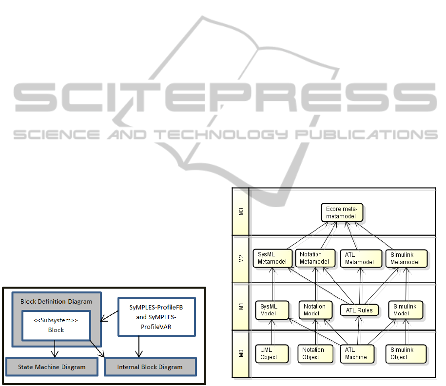
three SysML diagrams. These diagrams are: (i)
Block Definition diagram; (ii) Internal Block
diagram; and (iii) State Machine diagram. Figure 2
shows the relationship between the SysML diagrams
used and the application of SyMPLES profiles.
The root diagram is the Block Definition which
describes the main blocks of the system. A block can
be further represented either as an Internal Block
diagram describing its internals relationship based
on block instances or as a State Machine diagram
which represent its specific behavior.
The transformation process uses the SyMPLES-
ProfileFB to map blocks or blocks instances. It only
considers Internal Block or State Machine diagrams
from blocks that use the <<subsystem>> stereotype.
The Block Definition and Internal Block
diagrams can also have SyMPLES-ProfileVar
stereotypes applied to its elements. These
stereotypes support the configuration of a SPL
product in the application engineering activity.
Figure 2: SysML diagrams used and the use of SyMPLES
Profiles.
3.2 Execute ATL Transformation
ATL can use models based on the Eclipse Modeling
Framework (EMF) (EMF 2012) to perform
transformations. The EMF uses the standard Ecore
to represent its metamodels. Papyrus (Papyrus,
2012) and TOPCASED (TOPCASED 2012) are
examples of tools that have SysML graphical editors
based on Ecore metamodels. Graphical editors based
on Ecore uses two synchronized XMI files to store
the modeled elements: (i) domain file – represents a
UML file with attributes (eg. name, types and
relationship) and profile stereotypes; and (ii)
graphical file – one or more files can be associated
with the domain file. Papyrus SysML editors use a
Notation (Hunter 2012) file to persist graphical data
(eg. diagrams, size and position of elements). These
files are used by a Diagram Interchange (DI) (OMG
2006) file.
The ATL transformation gathers relevant
information from the SysML model configured and
generates a file based on a Simulink metamodel.
This intermediate transformation makes the
transformation process flexible to deal with other
SysML editors based on EMF. Figure 3 shows the
elements used in the ATL transformation in layered
metamodels. Layered metamodels are introduced in
(Ruscio 2007). The SysML configured model and its
Notation file are used as input to the transformation,
and a XMI Simulink model is generated. The
Simulink metamodel was adapted from (Biehl et al.
2010).
Figure 3: Models used in the ATL transformation in
layered metamodels.
To execute the transformation a set of ATL rules
are needed. Figure 4 shows the rules created in this
work to execute in an ATL machine. The
transformation rules include elements of a block
definition diagram, internal block diagrams and state
machines.
ICEIS2013-15thInternationalConferenceonEnterpriseInformationSystems
96
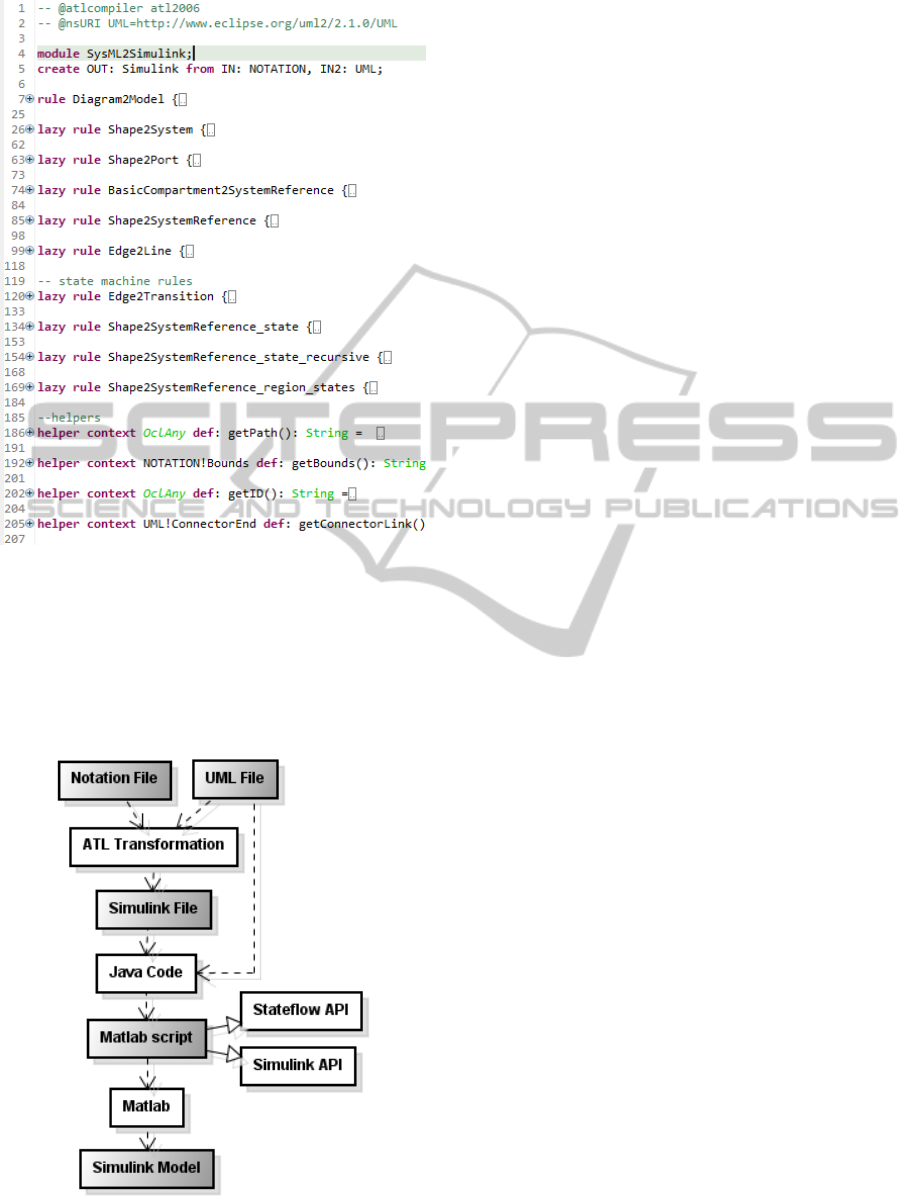
Figure 4: ATL rules used in the ATL transformation.
3.3 Generate Functional Blocks
The generation of functional blocks creates a script
that generates a Simulink model. Figure 5 shows the
sequence of artifacts (gray scale) produced. The
Notation and UML files are obtained from the
Figure 5: Artifact generation sequence of the
transformation process.
SyMPLES SPL artifacts and are used in the ATL
transformation. The UML file and the XMI file
created in the ATL transformation activity are used
to create a Matlab script using Java code. The UML
file is necessary as input to Java code because the
SyMPLES-ProfileFB stereotypes are necessary to
map elements in this activity. The ATL machine
cannot read profiles like metamodels.
The Matlab script is generated using Simulink
and Stateflow APIs to generate functional block
diagrams and state machine diagram respectively.
Running the script on the Matlab platform a
Simulink model can be created.
4 AN APPLICATION EXAMPLE
OF THE SYMPLES
TRANSFORMATION PROCESS
An application example is presented as a proof of
concept of the transformation process based on part
of the autopilot Yapa 2 (YAPA 2011). The autopilot
software runs in a controller board for Paparazzi
UAVs.
Initially the dynamics of aircraft movements
were analyzed. Based on the flight controller system
of Yapa 2, a SyMPLES model was created to handle
hypothetical commands generated by the autopilot.
This example shows the generated artifacts produced
by the transformation process and a simulation of
the Simulink model.
4.1 Flight Controller System
A Flight Control System reads information from the
sensors and guides the UAV to follow its predefined
plan. Its main components are sensors and the
autopilot (FAA 2008). In a typical cruise flight, the
UAV operates at a desired flight condition and
reaches the navigation points (waypoints) through
roll commands, however, the airspeed and altitudes
are fixed.
One objective of the flight controller is to
process flight commands generated by the
navigation system. It is divided into two main
controls, one to control vertical (altitude) and one
horizontal (navigation), which generate controls to
the servos.
4.2 SysML Flight Control
An example of a flight controller for UAVs
Paparazzi-type fixed-wing aircraft is presented. The
ApplicationEngineeringforEmbeddedSystems-TransformingSysMLSpecificationtoSimulinkwithinaProduct-Line
basedApproach
97
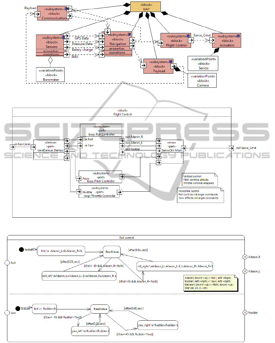
Figure 6: Initial Yapa 2 SPL architecture represented in SysML.
Figure 7: Internal block diagram for flight control.
Figure 8: State machine diagram for roll controller.
SysML diagrams were specified based on the
horizontal control of Yapa 2 autopilot. The Yapa 2
model was created by the SyMPLES processes and
represented with the support of Papyrus tool.
Figure 6 shows an example of an initial SPL
architecture for the Yapa 2 autopilot. The architecture
ICEIS2013-15thInternationalConferenceonEnterpriseInformationSystems
98
is represented by a SysML block definition diagram.
Blocks with stereotypes <<subsystem>> are mapped
to subsystems in Simulink. <<variationPoint>>
stereotypes represent elements that have variants to
be resolved in the SyMPLES SPL. Subsystems are
connected through its ports.
Figure 7 shows the flight control subsystem
represented by a SysML internal block diagram. The
diagram is composed of horizontal (controller roll)
and vertical motion controllers (pitch and throttle
controllers). Some navigation commands are
processed by the element loop: Roll
Controller that controls roll and yaw
movements using ailerons and rudder servos.
Figure 8 shows an example of a state machine
diagram created to the element loop: Roll
Controller. In this example, values are set to the
actuators according to the roll or yaw commands
received by the navigation subsystem. It is assumed
a fixed range of values that varies from -45 to +45
(degrees) to input commands and output (servos).
This range of values was used to simplify the
example. The states are named with expressions in
which the symbol "\ n" represents a line break that is
used to differentiate the state name and the
assignment of values in Stateflow model. Transitions
are represented by conditional expressions in which
input values and local variables are checked. When a
state is reached, servo values are increased or
decreased.
4.3 Simulink Flight Control
The flight controller for Simulink was generated
according to the transformation process. The
Simulink model was generated by running the
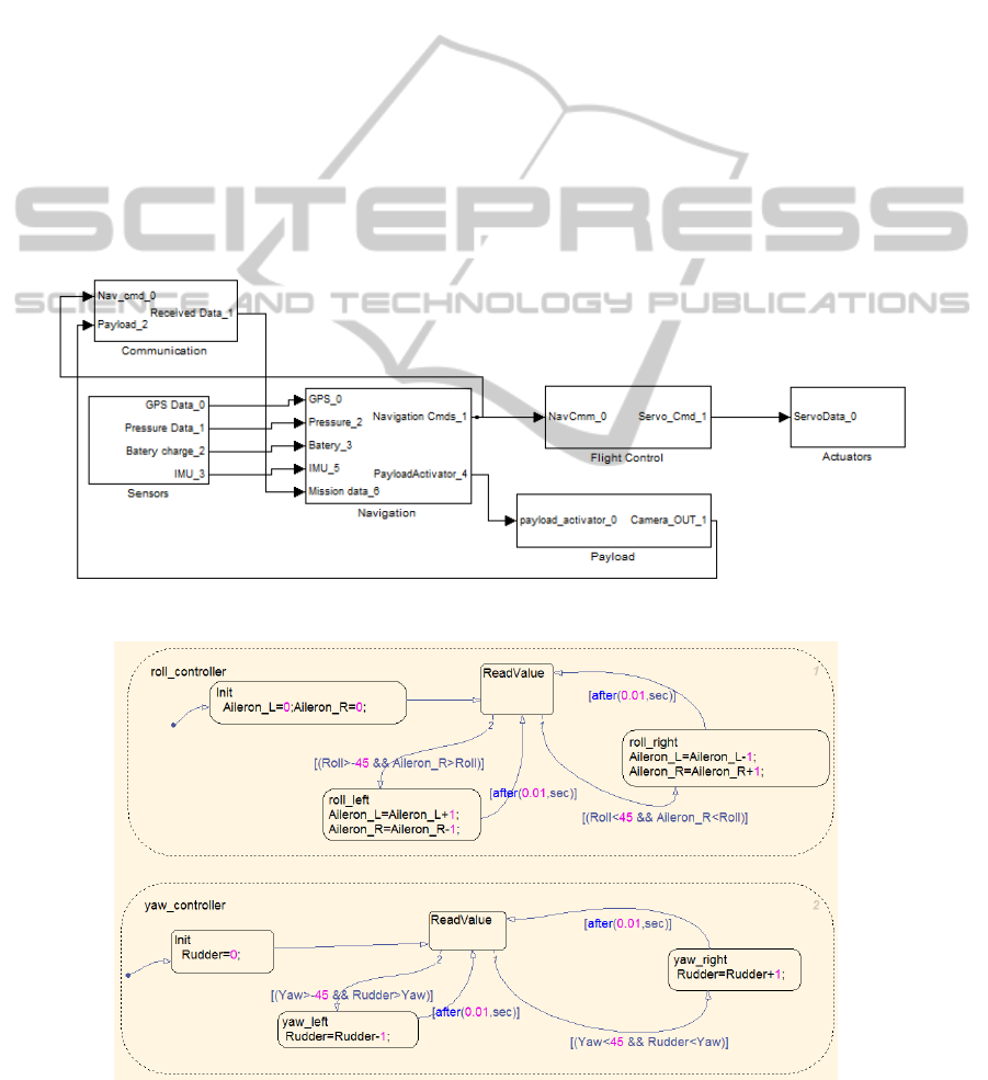
Matlab script. Figure 9 shows the initial architecture
transformed to Simulink based on the Block
Definition diagram for Yapa 2 (Figure 6). Only
elements with stereotypes of the SyMPLES-
Figure 9: Initial Yapa 2 architecture generated to Simulink.
Figure 10: Stateflow diagram generated from roll controller.
ApplicationEngineeringforEmbeddedSystems-TransformingSysMLSpecificationtoSimulinkwithinaProduct-Line
basedApproach
99
ProfileFB are considered in the transformation. The
connectors are processed only if the subsystems that
send and receive data have ports that are connected.
Figure 10 shows the state machine diagram
transformed to Stateflow in Simulink (Figure 8). In
this example, the name of the state is defined by the
first line and subsequent assignments are the setting
values for the servos commands.
4.4 Simulink Flight Control Simulation
Extra elements are added to allow the simulation of
roll control in the Simulink model of the flight
control generated. Test cases can be added to the
model using Simulink functional blocks named
signal builder. One signal builder was created to
simulate possible signals generated by the autopilot.
These signals include roll, yaw, pitch and throttle
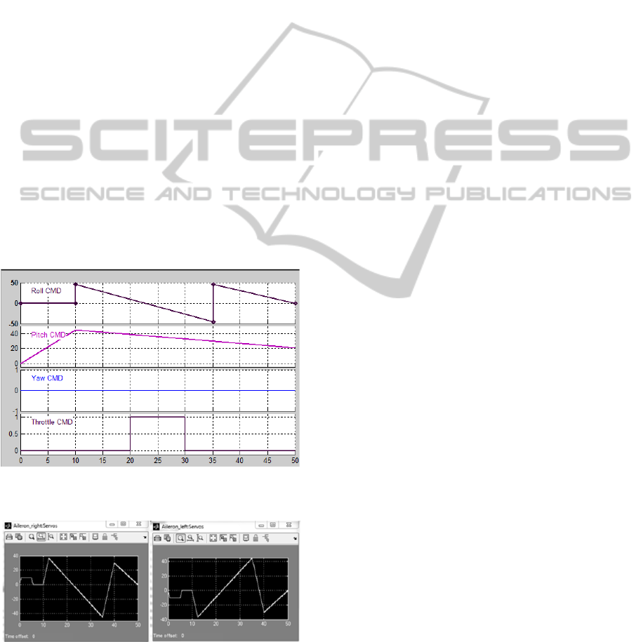
commands. Figure 11 shows an example for the
commands created by the signal generator. At the
second 10, the autopilot sends a command signal
"Roll 45" and "Pitch 45". The command roll is
updated and is gradually decreased until the value -
45 in the second 35. Then, it generates the command
"Roll 45". The behavior of this signal is to simulate
the sliding of a joystick.
Figure 11: Example of commands generated from
autopilot.
Figure 12: Visual result of ailerons command values.
Figure 12 visually shows the simulation results
for the servos “Aileron_right” and “Aileron_left”.
The command “Roll 10” was sent in the first 5
seconds simulating manual commands. Then the
autopilot signals of Figure 10 are sent to the
controller roll that set the values of servos to
perform the movement. At the second 10, the
command "Roll 45" must perform the right roll
movement and the right aileron must go up while the
left go down.
5 DISCUSSION AND RELATED
WORK
Some studies apply a transformation process from
UML to Simulink models. In Sjöstedt et al. (2008)
the transformation of Simulink models to UML is
performed. Using a Simulink model, a XMI file is
generated from the execution of a program
implemented in the Java language. The XMI file is
used to generate UML activities diagrams from an
ATL transformation. However, the applied domain
is different from that shown in this work. Moreover
the transformation is not applied to a SPL as
SyMPLES.
Biehl et al. (2010) presents a solution for the
domain of automobiles, which defines a process of
bidirectional transformation between Simulink
models and a UML extension called EAST-ADL.
However, this work considers only the domain of
automotive systems without a SPL as defined by
SyMPLES.
Brisolara (2007) presents a transformation
process from UML to Simulink models, but this
work uses UML activity diagrams as input. In our
work block definition, internal block and state
machine diagrams are used as input to the
transformation process.
6 CONCLUSIONS AND FUTURE
WORK
The SyMPLES transformation process focused on
the application engineering of a SPL, based on MDE
techniques. This supports the generation of platform-
specific models of SPL through the refinement of
abstractions which facilitates code generation.
SysML configured models are used as input for
transformation process and represent embedded
systems at the initial levels of development. The
SyMPLES-ProfileFB was extended to allow the
mapping and transformation of the models. The
process was evaluated by the controller board Yapa 2.
ICEIS2013-15thInternationalConferenceonEnterpriseInformationSystems
100

There are some limitations in the transformation
process: (i) initially only a set of Simulink functional
blocks are mapped by SyMPLES-ProfileFB
stereotypes. We have considered mainly functional
blocks related to the development of UAVs; and (ii)
initially only block definition, internal block and state
machine diagrams were used in the transformation
process.
Future works includes the use of additional
SysML diagrams in the transformation, and the
extension of the SyMPLES-ProfileFB to support
more functional blocks to others domains.
ACKNOWLEDGEMENTS
We are grateful to the Brazilian funding agencies
CNPq/INCT-SEC and FAPESP for supporting this
work.
REFERENCES
Biehl, M., Sjöstedt, C.-J. & Törngren, M., 2010. A modular
tool integration approach : experiences from two case
studies. 3rd Workshop on Model-driven tool and
Process Integration (MDTPI2010).
Braga, R. et al., 2011. Evolving Tiriba Design towards a
Product line of Small Eletric-Powered UAVs. In 1st
Brazilian Conference on Critical Embedded Systems.
pp. 63–72.
Brisolara, L. B., 2007. Strategies for Embedded Software
Development Based on High-level Models. UFRGS -
Porto Alegre.
Burch, J. R., Passerone, R. & Sangiovanni-Vincentelli, A.
L., 2001. Using Multiple Levels of Abstractions in
Embedded Software Design. In T. A. Henzinger & C.
M. Kirsch, eds. International Workshop on Embedded
Software. Berlin, Heidelberg: Springer Berlin
Heidelberg, pp. 324–343.
Czarnecki, K. & Helsen, S., 2003. Classification of Model
Transformation Approaches. In OOPSLA’03 Workshop
on the Generative Techniques in the Context of Model-
Driven Architecture. Anaheim, California, USA, p. 17.
Ebert, C. & Jones, C., 2009. Embedded Software: Facts,
Figures, and Future. Computer, 42(4), pp.42–52.
EMF, 2012. Eclipse Modeling Framework Project.
Available at: http://www.eclipse.org/modeling/emf/.
FAA, F. A. A., 2008. Flight Controls. In Pilot’s Handbook
of Aeronautical Knowledge. p. 12.
Fragal, V., Junior, E. & Gimenes, I., 2011. Mapping
Software Product Line Features to Unmanned Aerial
Vehicle Models. In 1st Brazilian Conference on Critical
Embedded Systems. pp. 49–54.
Hunter, A., 2012. Graphical Modeling Framework (GMF)
Notation. Available at: http://www.eclipse.org/
projects/project.php?id=modeling.gmp.gmf-notation.
Linden, F., Schmif, K. & Rommes, E., 2007. Software
Product Lines in Action, Springer.
Lykins, F. M., 2000. Adapting UML for an Object-Oriented
Systems Engineering Method (OOSEM). In INCOSE
International Symposium.
Marwedel, P., 2010. Embedded System Design: Embedded
Systems Foundations of Cyber-Physical Systems,
Springer; 2nd ed. 2011 edition (December 3, 2010).
Obeo, 2006. Atlas Transformation Language. Available at:
http://www.obeo.fr/pages/atl-pro/en.
Oliveira, E. A. J., Gimenes, I. M. S. & Maldonado, J.C.,
2010. Systematic Management of Variability in UML-
based Software Product Lines. Journal of Universal
Computer Science, 16, pp.2374–2393.
OMG, 2006. Diagram Interchange. OMG, p.86. Available
at: http://www.omg.org/cgi-bin/doc?formal/06-04-04
[Accessed October 11, 2012].
Papyrus, 2012. Open Source Tool for Graphical UML2
Modelling. Available at: http://www.papyrusuml.org/
scripts/home/publigen/content/templates/show.asp?P=1
28&L=EN&ITEMID=12.
Pastor, E., Lopez, J. & Royo, P., 2006. An Embedded
Architecture for Mission Control of Unmanned Aerial
Vehicles. In 9th EUROMICRO Conference on Digital
System Design (DSD’06). IEEE, pp. 554–560. Available
at: http://ieeexplore.ieee.org/lpdocs/epic03/wrapper.
htm?arnumber=1690087 [Accessed December 12,
2012].
Polzer, A., Kowalewski, S. & Botterweck, G., 2009.
Applying software product line techniques in model-
based embedded systems engineering. In 2009 ICSE
Workshop on Model-Based Methodologies for
Pervasive and Embedded Software. IEEE, pp. 2–10.
Ruscio, D., 2007. Specification of model transformation and
weaving in model driven engineering. Università di
L’Aquila. Available at: http://www.di.univaq.it/
diruscio/PhDThesis_DiRuscio.pdf.
Silva, R. F., 2012. SyMPLES : Uma Abordagem de
Desenvolvimento de Linha de Produto para Sistemas
Embarcados baseada em SysML. Universidade Estadual
de Maringá.
Simulink, 1994. Simulation and Model-Based Design.
Available at: http://www.mathworks.com/products/
simulink/.
Simulink Coder, 2012. Real-Time Workshop. Available at:
http://www.mathworks.com/products/simulink-
coder/index.html.
Sjöstedt, C.-J. et al., 2008. Mapping Simulink to UML in
the design of embedded systems:Investigating scenarios
and transformations. In OMER4 Post-proceedings,
2008. pp. 137–160.
Steiner, E. M., 2012. Gerenciamento de configuração de
uma linha de produtos de software de veículos aéreos
não tripulados. USP.
SysML, 2008. OMG Systems Modeling Language. OMG,
p.234.
TOPCASED, 2012. The Open-Source Toolkit for Critical
Systems. Available at: http://www.topcased.org/.
YAPA, 2011. YetAnotherPaparazziAutopilot v2. Available
at: http://paparazzi.enac.fr/wiki/YAPA/v2.0.
ApplicationEngineeringforEmbeddedSystems-TransformingSysMLSpecificationtoSimulinkwithinaProduct-Line
basedApproach
101
