
Detecting Precise Iris Boundaries by Circular Shortest
Path Method
Ivan Matveev
1
and Ivan Simonenko
2
1
Computing Centre of Russian Academy of Sciences,
Vavilov str., 40, Moscow, 119333, Russia
2
Moscow Institute of Physics and Technology,
Institutskii per., 9, Dolgoprudny, Moscow Region, 141700, Russia
Abstract. Modified circular shortest path detection method is applied for re-
fining pupil and iris boundaries using given approximate pupil and iris circles.
Brightness gradient direction is employed to choose image pixels, which may be-
long to pupil or iris boundary. Using initial approximate circles allows the method
to work in a narrow ring, which contains only single circular contour. Under these
conditions the method allows to correctly handle almost all images used for iris
recognition tasks and appears to be more precise than human expert in mark-
ing the pupil border. The method was tested with public domain iris databases,
containing more than 80000 images totally.
1 Introduction
Iris recognition is one of main biometric identification technologies. Detecting iris bor-
ders in image is an important part of this method. Iris pattern in image is represented as
a ring enclosed between two approximately circular and approximately concentric con-
tours: inner border,which is an iris-pupil boundary,and outer border,which is iris-sclera
boundary. Both boundaries are approximated by circles with good precision, however
there are applications demanding more precise shape detection and description [1]. This
particularly concerns inner (i.e. pupil) boundary. As a rule, human pupil is close to cir-
cle in shape, however in most cases it is not an ideal circle and has irregular deviations
with relative magnitude around 5-10% [2]. Thus, a problem appears to detect a contour,
which has approximately circular shape and encloses dark region (pupil) in relatively
brighter background. Apparently, iris can be detected as a dark circular region in a
background of sclera, in case there are no or small occlusions by eyelashes and eyelids.
Problem of detecting shapes modelled by circles and ellipses (i.e. regular shapes) have
attracted much attention and many methods are developed. Rich variability of methods
applied to determining iris boundaries is reviewed in [3,4]. Much less attention is at-
tracted to tracking the boundaries to their irregular (although close to circle) shape that
may allow better recognition performance. Many researchers limit themselves to just
an iteration of same detection algorithm [5, 6] or to applying same detection method
in different scale under multi-scale image processing scheme [7,8]. Special methods
for refinement of the boundaries, which track roundish but irregular shapes with good
Matveev I. and Simonenko I..
Detecting Precise Iris Boundaries by Circular Shortest Path Method.
DOI: 10.5220/0004394501010108
In Proceedings of the 4th International Workshop on Image Mining. Theory and Applications (IMTA-4-2013), pages 101-108
ISBN: 978-989-8565-50-1
Copyright
c
2013 SCITEPRESS (Science and Technology Publications, Lda.)

precision and tolerate noise were developed to much less extent. The authors could find
that only one approach of active contours was specially targeted and tested with the
task of iris border refinement [9–11]. Here a method of circular shortest path proposed
in [12] is modified and applied to the problem of refining pupil and iris borders.
2 Circular Shortest Path Algorithm
There are plenty of methods performing detection of shortest path in images. Specific
feature of the CSP approach among them is that it starts from an a-priory detected
point that is claimed to be an approximate contour center (or at least is lying inside the
contour). In the refinement task stated here initial data for the method are even more
detailed: center position and radius of approximating circle are given. Since the contour
passes round a given point it is reasonable to perform a polar transformation with the
pole in this point, which simplifies both representation and calculations. (Indeed, polar
transformation is a very common issue in iris image processing.) Polar transformation
renders a ring shape to a rectangle. This rectangle can be positioned so as to have its
top side being a circle enclosing the proposed contour (enough big circle should be
taken), and bottom side is to be enough small circle inside the contour. Then left side
and right side both correspond to a coordinate origin line, let it be OX half-axis. The
radial coordinate of polar system is transformed to abscissa of the rectangle and angle
coordinate becomes ordinate. Image in OXY domain is transformed to Oρφ domain
and is also represented as a rectangular raster. Define the size of the raster as W ∗ H
pixels. Call it polar representation rectangle, see. Figure1.
After the polar transformation circular path location task is rendered to a problem
of detecting optimal path between left and right sides of rectangle, under the condition
that terminal points at the sides have same vertical coordinate. Since contour is close to
circle in shape and pole of the polar transform is inside it, the polar representation of
contour is univalent, i.e. only one radius of contour corresponds to each angle value, and
the contour can be expressed in terms of function ρ(φ), φ ∈ [0; 2π], ρ(0) = ρ (2π). Fur-
ther, assuming that pole of transformation is not very close to the contour line (in other
words, is near the center of the contour), one can state that derivative of radius by angle
is limited: dρ/dφ 6 1. In raster polar representation rectangle of size W ∗ H this func-
tion becomes a discrete sequence {ρ
n
} (or accounting for both coordinates {(n, ρ
n
)}),
n ∈ [0, W − 1], ρ
n
∈ [0; H − 1]. Limitation to derivative becomes |ρ
n+1
− ρ
n
| 6 1.
Condition to equal value at ends becomes |ρ
W −1
− ρ
0
| 6 1. Thus the contour is repre-
sented as a chain of points in rectangular raster, each column of the raster contains one
and only one contour point, the points in adjacent columns belong to same or adjacent
rows, the first and last points also belong to same or adjacent rows. Hereinafter this
chain of points is called path S = {ρ
n
}
W −1
n=0
. Figure2 illustrates the possible paths of a
contour, if tracked from left to right. A path from point with coordinates (φ; ρ) = (2; 3)
can go to points (3; 2) − (3; 4), from point (5; 1) - into points (6; 1) and (6; 2), and if
staring point is (1; 2) ending points can be (8; 1) − (8; 3).
Introduce the cost of transition between points (n, ρ
′
) and (n + 1, ρ
′′
) in adja-
cent columns in polar representation. Define it as C((n, ρ
′
), (n + 1, ρ
′′
)), or shorter
C
n
(ρ
′
, ρ
′′
). It is composed from ”inner” and ”outer” parts: C(ρ
′
, ρ
′′
) = C
(I)
(ρ
′
, ρ
′′
) +
102
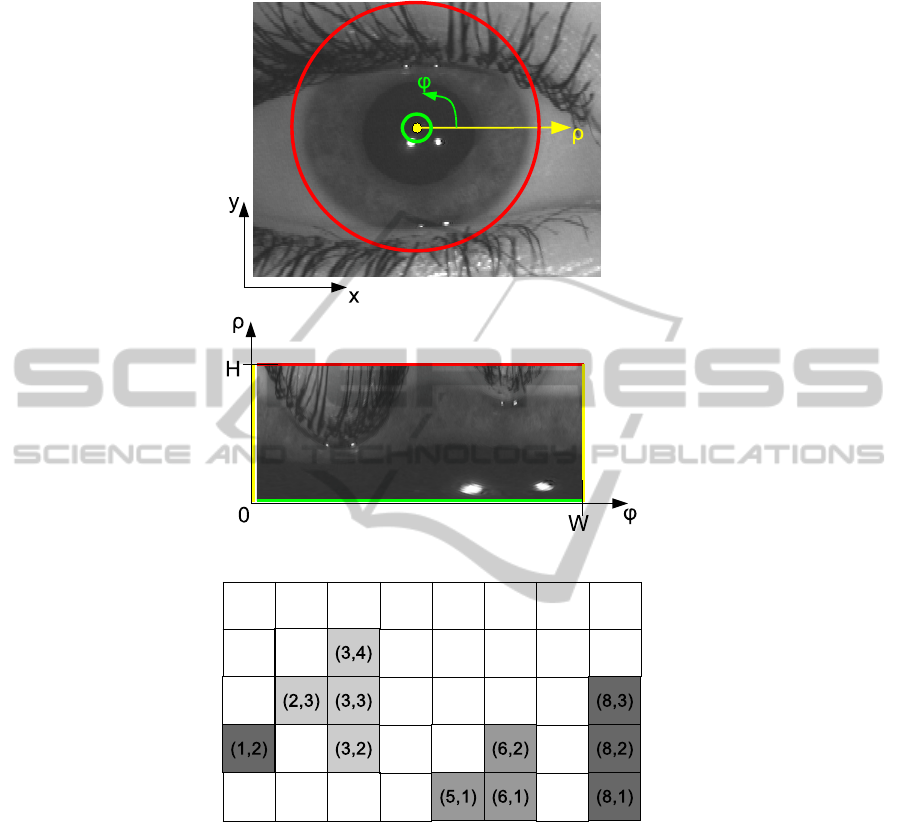
Fig.1. Sample of polar transform applied to an iris image.
Fig.2. Possible contour paths in case of limited derivative dρ/dφ 6 1.
C
(O)
(ρ
′
, ρ
′′
). Inner part conditions the shape of the contour and favours straight hori-
zontal lines (which are circles in original OXY domain):
C
(I)
n
(ρ
′
, ρ
′′
) =
0 , ρ
′
= ρ
′′
T
1
, |ρ
′
− ρ
′′
| = 1
∞ , otherwise
The constant T
1
> 0 is the parameter which determines a ”force” compelling the
contour to be a straight line in polar representation (i.e. circle with center in given
103

pole in original image). The value of T
1
depends on parameters of polar transform,
namely from the scale of polar representation. While inner part depends on contour
shape only, and does not depend on image, outer part is estimated from image charac-
teristics and binds the contour to image. The outer part is the cost of passing through
point (n, ρ
′
) determined from local image characteristics in the point, and does not de-
pend on contour shape: C
(O)
n
(ρ
′
, ρ
′′
) = w((n, ρ
′
)). For a given path S = {ρ
n
}
W −1
n=0
total cost is the sum of all transitions between adjacent points in the path: C(S) =
C((0, ρ
0
), (W, ρ
W
)) =
W −1
P
n=0
C
n
(ρ
n
, ρ
n+1
). The optimal contour is the sequence min-
imizing the whole cost:S
∗
= arg min
S
C(S). This discrete optimization problem may
be solved by some known method, for instance, greedy algorithm as proposed in [12].
3 Application to Pupil Boundary Refinement
Application of CSP method to the problem of iris boundaries detection has specific is-
sues. First, it is obvious that there are two circular contours in the image of an eye: pupil-
iris boundary and iris-sclera boundary. Sometimes there is a contour of ophthalmic lens
also. This makes it difficult to apply CSP method to initial detection of these borders,
since detected contour can be any of these two and there is no perfect way of discrim-
inating these two cases. This application was treated in [13]. So, feasible task for CSP
method is refinement of already detected pupil and iris borders. Under this condition
initial approximate locations of both iris boundaries is known. Thus the algorithm can
run for a narrow ring containing the target boundary, rather than for the whole image.
For a narrow polar representation rectangle with H < 30 a straightforward exhaustive
search is faster than other elaborated algorithms.
The exhaustive search of optimal circular path is performed recursively as a set of
steps. Each step involves a column of the polar representation raster (points with same
value of φ). The cost of passing from a point (0, ρ
′
), in the first (left) column to the
point (n, ρ
′′
), in current column: C((0, ρ
′
), (n, ρ
′′
)) ≡ C
(n)
(ρ
′
, ρ
′′
). Since both ρ
′
and
ρ
′′
range in [1, H], it is necessary to calculate H
2
values C
(n)
. They are calculated
recursively starting from C
(1)
(ρ
′
, ρ
′′
) = 1/δ(ρ
′
, ρ
′′
). For each next column the cost of
arriving to a point in it is a minimal sum of cost of arriving to some point ρ
′′′
in the
previous column and the cost of transition between adjacent columns:
C
(n+1)
(ρ
′
, ρ
′′
) = min
ρ
′′′
(C
(n)
(ρ
′
, ρ
′′′
) + C
n
(ρ
′′′
, ρ
′′
)) =
= min
C
(n)
(ρ
′
), ρ
′′
) + w(n, ρ
′′
) ,
C
(n)
(ρ
′
), ρ
′′
+ 1) + w(n, ρ
′′
+ 1) + T
1
,
C
(n)
(ρ
′
), ρ
′′
− 1) + w(n, ρ
′′
− 1) + T
1
,
The incoming path for each point in the column (i.e. which of the three sums gave mini-
mum) is recorded. At the final step (which has number W +1) H
2
valuesC
(W +1)
(ρ
′
, ρ
′′
)
are obtained. Only values with ρ
′
= ρ
′′
correspond to closed contours. So the cost of
optimal closed contour is min
ρ
C
(W +1)
(ρ, ρ) and it starts and ends at ρ
∗
W +1
≡ ρ
∗
0
=
104

arg min
ρ
C
(W +1)
(ρ, ρ). From the detected radius ρ
∗
W +1
contour is tracked back easily
from the recorded incoming paths.
Now consider the outer cost of transition via point C
(O)
(φ, ρ) = w(φ, ρ). From the
task formulation it is clear that w(φ, ρ) function should be constructed so as to be small
in the points corresponding to the contour and big in other points. Contour points have
strong brightness gradient value, thus points with small gradient should be rejected.
This is done in the source image by checking the condition kgk > T
2
in each image
pixel and selecting only pixels, which satisfy this condition as possible contour points.
Here g is is brightness gradient vector and T
2
is a threshold. The value of T
2
is selected
so as to suppress false gradients occurring due to image noise. If 3 ∗ 3 Sobel mask is
used for gradient calculation the treshold can be set T
2
= 6
√
2 max{σ, 2}, where σ is
the brightness standard deviation caused by noise.
Next task-specific feature is that both pupil and iris are dark regions in brighter
background, hence brightness gradients are directed outwards of the contour, and the
angle between gradient in the point and radius-vector to this point from the center of the
contour is enough small. This condition can be set as: arccos(
x·g
kxk kgk
) < T
3
. The value
of threshold T
3
depends on the quality of the center detection algorithm, treated as an
average (or maximum, or percentile) ratio of the distance D between detected center and
true center to the radius R of the contour. It is calculated as T
3
= arcsin(D/R). Figure3
shows the points of an image from Figure1, satisfying both of the aboveconditions. The
cost of transition is set to zero for these points, and is set to T
1
for all other points.
Fig.3. Sample of gradient map with direction condition imposed and its polar transform.
With these modifications CSP method was applied to the refinement of iris bound-
aries
4 Experiments
Tests of CSP performance were done with the following iris image databases from
public domain: UBIRIS.v1 [14], CASIA-IrisV3 [15], ND-IRIS [16]. Eye images were
105

processed by human expert who indicated pupil and iris borders with most likely ap-
proximating circles. Thus each image was attributed with center positions and radii
of pupil and iris circles. These data (call it expert marking) were then considered as
”ground-truth” and were used for method verification. Unfortunately, there is no simple
way to obtain refined border contours, that can be treated as ”ground-truth”. Human
operator can manually mark quite a small share of huge image databases with such
contours. This task is much more tedious and error-prone than marking circles.
So, direct tests of comparing refined borders to some ”ground-truth”data and testing
the quality of refinement method are not possible. Indirect methods were used instead.
Refined borders were ”simplified” back to circle, which has center in the point of mass
center of the area, enclosed to the refined border. Radius of simplified circle was set to
equate areas enclosed in this circle and in refined border. Call this simplified represen-
tation of refined border refined circle. Although again circle, refined one does not match
the original approximation, and it can be a better approximation somehow.
Two approaches were used to compare original and refined circles. First approach
is direct matching against expert marking, to estimate which kind of detection is more
precise. Images from all three databases were used [14–16]. Three ways were used to
supply initially detected pupils and irises. First, expert marking data itself were spoiled
with random noise to simulate improper detection. Second, Masek’s algorithm [17]
was used. Third, an approximate method of detection by circular brightness gradient
projections [18] was employed. Mean square deviations of pupil center position and
radius from expert marking were calculated for all three ways for original and refined
circles.
Table 1. Error in pupil detection by various methods.
Method Average error of pupil radius de-
tection in three databases, pixels
Average error of pupil center posi-
tion in three databases, pixels
UBI NDIRIS CASIA UBI NDIRIS CASIA
Spoiled expert 8.16 8.16 8.16 5.77 5.77 5.77
Masek 4.65 7.23 5.15 3.24 5.59 3.67
Matveev 7.78 6.34 5.81 5.13 4.27 4.11
Spoiled expert, refined 5.59 2.52 1.86 3.26 1.63 1.53
Masek, refined 4.07 2.41 1.58 2.88 2.07 1.14
Matveev, refined 4.89 2.09 1.45 3.51 1.52 1.09
CSP refinement makes improvement in precision of initial detection, although it is
not effective for highly noisy images like UBIRIS.v1.
Second approachto estimate the quality and usability of refinement is judging by the
”final characteristic”, that is precision of iris recognition. The value of equal probability
of recognition errors of first and second kind (equal error rate, EER) was chosen as
such characteristic. CASIA Iris-Lamp database [15] was used for tests, which contains
16213 images of 819 eyes of 411 subjects. The following steps were performed here.
Templates were created from images of database by the algorithm [9]. For its work the
algorithm uses circular approximations of pupil and iris in each image. At first, pure
expert marking was used for this purpose. The set of obtained templates was matched
against itself and the EER value was estimated. For original expert marking its value is
106

EER=0.752%. Then expert marking of pupils was refined by the proposed method, and
same operations of template generation, matching and EER evaluation were done, with
resulting EER=0.390%.
So, the refinement of pupil by circular shortest path method appears to reduce the
recognition error. This can be explained by the imprecise marking of human expert.
5 Conclusions
Location of iris borders with high precision is an important task in automatic iris biom-
etry. Though much attention is paid to iris border location in general, only few re-
searchers tried developing special methods for iris border refinement after their initial
detection. The authors have treated this aspect of iris border location problem with the
help of circular shortest path optimization method. The CSP detection algorithm was
modified to fit the peculiar properties of the task. The results of experiments show that
refinement of pupil-iris boundary by CSP may be a useful addition to general scheme
of iris border location.
References
1. ISO/IEC 19794-6:2005 Information technology – Biometric data interchange formats – Part
6: Iris image data, 2005.
2. Kansky, J.J.: Clinical Ophthalmology: a Systematic Approach, Elsevier, London, 2003.
3. Bowyer, K., Hollingsworth, K., and Flynn, P.: Image understanding for iris biometrics: A
survey // Computer Vision and Image Understanding. 2008. P.281–307.
4. Bowyer, K., Hollingsworth, K., and Flynn, P.: A survey of iris biometrics research: 2008-
2010 // Handbook of Iris Recognition, Mark Burge and Kevin W. Bowyer, editors. Springer.
2012.
5. He, Z., Tan, T., Sun, Z., and Qiu, X. Toward accurate and fast iris segmentation for iris
biometrics. In IEEE PAMI. 2009. V.31. P.1670–1684.
6. Maenpaa, T. An iterative algorithm for fast iris detection. In Int. Workshop on Biometric
Recognition Systems. Beijing. China.. 2005. P.127.
7. Nabti, M., Ghouti, L., and Bouridane, A. An effective and fast iris recognition system based
on a combined multiscale feature extraction technique. In Pattern Recognition. 2008. V.41.
P.868–879.
8. Pan, L., Xie, M., and Ma, Z. Iris localization based on multiresolution analysis. In Proc.
19th Intern. Conf. Pattern Recognition. Tampa, Florida, USA.. 2008. P.1–4.
9. Daugman, J.: New methods in iris recognition // IEEE Trans. on Systems, Man and Cyber-
netics. Part B: Cybernetics. 2007. V.37. P.1167-1175.
10. Ross, A., Shah, S.: Segmenting non-ideal iris using geodesic active contours // Biometrics
Symposium: Special Session on Research at the Biometric Consortium Conf. Baltimore.
USA, 2006. P.16.
11. Koh, J., Govindaraju, V., Chaudhary, V.: A robust iris localization method using an active
contour model and hough transform // 20th Int. Conf. on Pattern Recognition. Istanbul.
Turkey. 2010. P.2852-2856.
12. Sun, C., Pallottino, S.: Circular shortest path in images // Pattern Recognition. 2003. V.36.
N.3. P.709-719.
107

13. Matveev, I.A.: Circular Shortest Path as a Method of Detection and Refinement of Iris Bor-
ders in Eye Image // Journal of Computer and Systems Sciences International. 2011. V.50.
N.5. P.778-784.
14. Proenca, H., Alexandre, L.A.: UBIRIS: A noisy iris image database // 13th Intern. Conf. on
Image Analysis and Processing. V.3617. Cagliari, Italy: Springer, 2005. P.970-977.
15. Chinese academy of sciences institute of automation (CASIA), CASIA Iris image database
http://www.cbsr.ia.ac.cn/IrisDatabase.htm, 2005.
16. Phillips, P.J., Scruggs, W.T., O’Toole, A.J. et al. Frvt2006 and ice2006 large-scale experi-
mental results // IEEE PAMI. 2010. V.32. .5. P.831-846.
17. Masek, L.: Recognition of human iris patterns for biometric identification.
http://www.csse.uwa.edu.au/ pk/studentprojects/libor, 2003.
18. Matveev, I.A.: Detection of Iris in Image By Interrelated Maxima of Brightness Gradient
Projections // Applied and Computational Mathematics, 2010, V.9, No.2, pp.252-257.
108
