Remote Laboratories in the Cloud
A Digital Holographic Microscope
Wolfgang Osten, Giancarlo Pedrini and Marc Wilke
Institute of Technical Optics, University of Stuttgart, Pfaffenwald Ring 9, Stuttgart, Germany
Keywords:
Remote Laboratory, Remote Metrology, Virtual Laboratory, Cloud Computing, Comparative Digital Holog-
raphy, Optical Shape Measurement, Master-Sample-Comparison.
Abstract:
Cloud computing introduces a new paradigm for using IT resources, the often quoted “everything as a service”,
where resources are leased and paid for on a time-limited ad-hoc basis. Related advances in information tech-
nology open up the potential of combining optical systems with net based infrastructures, allowing for remote
inspection and virtual metrology. Coupling the cloud to physically existent laboratories provides universal
access to non-virtual resources. In this paper, we report our recent work on building a remote laboratory for
digital holographic metrology. We describe the architecture and the techniques involved in setting up the re-
mote controlling metrology system. Further consideration will be given to the integration into an advanced
infrastructure for remote experimentation, data storage and publication.
1 INTRODUCTION
Cloud computing can be defined by the following
three aspects: “The illusion of infinite computing re-
sources, available on demand”, “the elimination of
an up-front commitment by the cloud user”, and “the
ability of paying for use of computing resources on
a short term basis as needed” (Amburst et al., 2009).
The goal is to provide virtual computing resources as
a utility over the net. Three basic levels of service can
be distinguished, defined by the types of capabilities
provided (Wang et al., 2008)”:
1. Hardware as a Service (HaaS): Access to com-
plete computer systems, grids or data centers is
provided, the user can install and run his own sys-
tem and software as needed (e.g. Google App En-
gine (Goo, a) or Amazon EC2 - Amazon Elastic
Compute Cloud (Ama, )).
2. Software as a Service (SaaS): Software or appli-
cations are provided, the actual hardware and plat-
form remains completely transparent for user (e.g.
Google Doc (Goo, b)).
3. Data as a Service (DaaS): Access to data for stor-
age and semantic access over the net is provided
(e.g. Google’s Bigtable (Chang et al., 2006))
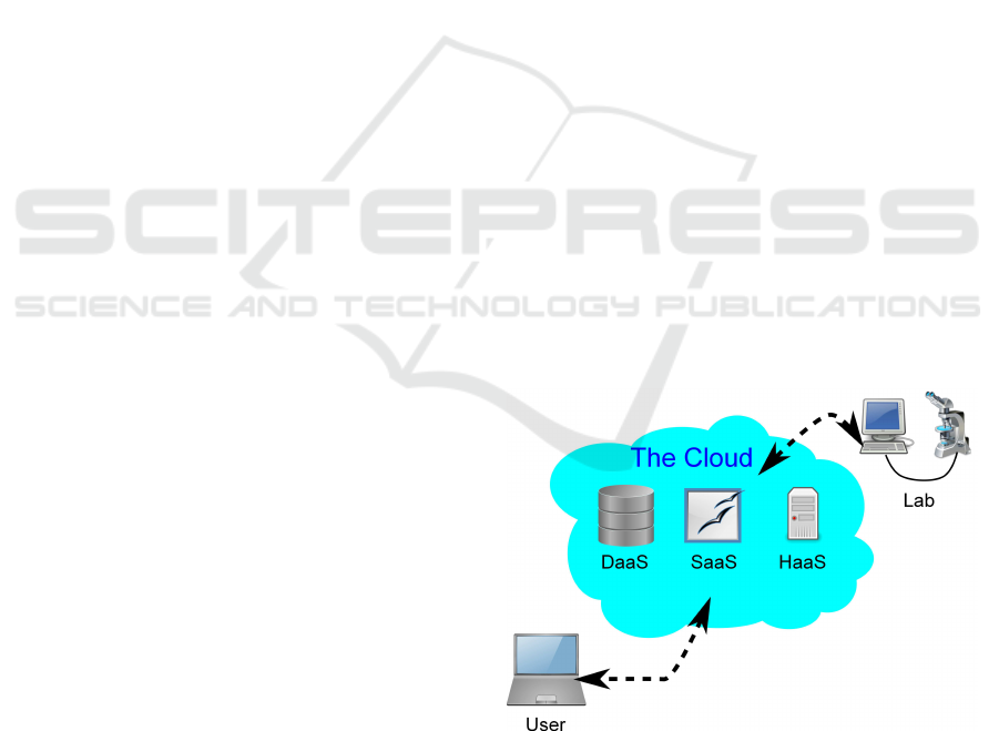
In our work we are extending this paradigm, or,
more precisely, Software as a Service, to include
non-computational hardware, in our case a physi-
Figure 1: Accessing a remote lab through The Cloud.
cally existent laboratory for optical metrology (see
Figure 1). However, the restrictions of such an im-
plementation are obvious: the access is limited to
computer resources (computing power, software, data
storage, and service). The embedding of external,
non-computational facilities is not addressed in the
above concept. Therefore our approach extends this
paradigm by adding non-computational hardware, in
our case a physically existent laboratory for optical
metrology (see Figure 1).
The idea of remote and virtual metrology has been
reported as early as 2000 (Osten, 2000; Osten et al.,
2001) with a conceptual illustration by use of compar-
ative digital holography (Osten et al., 2002) , aimed at
374
Osten W., Pedrini G. and Wilke M..
Remote Laboratories in the Cloud - A Digital Holographic Microscope.
DOI: 10.5220/0004377103740381
In Proceedings of the 3rd International Conference on Cloud Computing and Services Science (CLOSER-2013), pages 374-381
ISBN: 978-989-8565-52-5
Copyright
c
2013 SCITEPRESS (Science and Technology Publications, Lda.)

the comparison of two nominally identical but physi-
cally different objects, e.g., master and sample, in in-
dustrial inspection processes. In a first step, a digital
hologram of the master is generated and stored, allow-
ing transmission through the Internet. This provides
instant, global access to the complete optical informa-
tion of the master object. For comparison, the mas-
ter hologram is optically reconstructed using a spatial
light modulator (Osten et al., 2002; Baumbach et al.,
2006; Kohler et al., 2008) and projected onto a sample
under inspection, resulting in interferometric patterns
that can be analyzed to retrievethe differencebetween
the master and the test object. However, the concept
of remote and virtual metrology can be extended far
beyond this. For example, it does not only allow for
the transmission of static holograms over the Inter-
net, but also provides an opportunity to communicate
with and eventuallycontrol the physical set-up of a re-
mote metrology system. Furthermore, the metrology
system can be modeled in the environment of a 3D
virtual reality using CAD or similar technology, pro-
viding a more intuitive interface to the physical setup
within the virtual world. An engineer or scientist who
would like to access the remote real world system can
log on to the virtual system, moving and manipulating
the setup through an avatar and take the desired mea-
surements. The real metrology system responds to the
interaction between the avatar and the 3D virtual rep-
resentation, providing a more intuitive interface to the
physical setup within the virtual world. The measure-
ment data is stored and interpreted automatically for
appropriate display within the virtual world, provid-
ing the necessary feedback to the experimenter. Such
a system opens up many novel opportunities in indus-
trial inspection such as virtual remote testing (Osten,
2000) and controlling.
With the development of broadband Internet and
software for remote control, we are able to make
progress toward this goal: to build a remote metrol-
ogy system based on digital holography. Our proto-
type, being developed within the framework of the
BW-eLabs project(Jeschke et al., 2011) , does not in-
tend to implement all the functionality stated above
in the current project phase. Instead, we are build-
ing a remote experimental system that can perform
deformation measurement on small objects such as
MEMS under various loads on nanometer scale, and
3D holographic microscopic imaging of (biological)
samples on micron scale (Kemper and von Bally,
2008; Schnekenburger et al., 2007) by providing uni-
versal access through the Internet. Digital hologra-
phy offers several fundamental advantages in the field
of microscopy, ranging from increased contrast in the
phase reconstruction compared to intensity in trans-
parent objects such as biological samples to numerical
focusing in arbitrary reconstruction planes (Langeha-
nenberg et al., 200y; K¨uhn et al., 2009). The phys-
ical hardware is controlled through LabView (lab, )
and will be connected to a 3D virtual reality, based on
the Open Source project Wonderland (Won, ) . Data
storage and retrieval, including a search engine and
meta data generation are handled through the Open
Source project eSciDoc(eSc, ; Razum et al., 2009)
. The system is primarily designed for deployment
in the field of scientific research, in particular for in-
ternational collaboration in joint experiments. Never-
theless, it is equally useful in education. In the field
of chemistry and chemical engineering, such weblabs
have been widely employed for education of various
curriculum at many international leading universities
including MIT in USA and University of Cambridge
in the UK (Selmer et al., 2007) . We will not address
the details of the security aspects implemented in the
infrastructure, instead focusing on the technical as-
pects of the actual experiment, the remote control and
the storage of the results.
2 APPLICATIONS FOR REMOTE
LABORATORIES IN OPTICAL
METROLOGY
In the following we will provide two examples for re-
mote laboratories. The first, an application of com-
parative digital holography demonstrates how two
objects in very distant places can be compared on
a micrometer scale while the second is a proof-of-
principle implementation of a digital holographic mi-
croscope.
2.1 Remote Comparative Digital
Holography
Holographic interferometry offers a method for shape
control with interferometric sensitivity. However, the
need of matching microstructures results in an im-
portant consequence for the conventional procedure:
the limitation to the comparison of an object with it-
self in different states, such as deformation from me-
chanical or thermal loading. Therefore, for the com-
parison of the shapes or the responses to a load of
two nominally identical but physically different ob-
jects (master-sample comparison) it was necessary to
evaluate the resulting interferograms independently
and to compare the resulting data numerically. A
more elegant approach, the so-called Comparative
Holographic Moir Interferometry, was introduced by
RemoteLaboratoriesintheCloud-ADigitalHolographicMicroscope
375
Rastogi(Rastogi, 1984) and Simova et al(Sainov and
Simova, 1989). The method is based on the incoher-
ent superposition of the involved interferograms and
the evaluation of the resulting Moir pattern. The ap-
pearing Moir fringes provide a direct indication of
the difference between the both objects. However,
the sensitivity of this method is limited due to the
poor signal-to-noise ratio in the Moir image. D.B.
Neumann published a completely new holographic
technique in 1980, which enables the direct detec-
tion of the deviations of two objects with different
microstructure. He called it Comparative Hologra-
phy (Neumann, 1980). The innovative aspect of this
method was the coherent illumination of every state
of the sample with the conjugated wave front of the
corresponding state of the master. The wave front
of the master plays the role of a coherent mask for
the adaptive illumination of the sample. Although the
procedure has interferometric sensitivity its practical
relevance is still low because of the complicated ex-
perimental background. A series of valuable contri-
butions with respect to the improvement of this tech-
nique were made by Fzessy and Gyimesi(F¨uzessy and
Gyimesi, 1984) who introduced the application of the
double reference beam technique for the independent
storage and reconstruction of both object states. In the
following we describe the basic principles of Compar-
ative Digital Holography(Ostenet al., 2001) and show
the advantages of this new procedure in examples
dealing with issues of optical shape control. Further-
more the possibility of remote shape control by mak-
ing the coherent masks globally by data transfer via
the Internet is discussed. Comparative Digital Holog-
raphy is a new method for direct holographic compar-
ison of the shape or the deformation of two nominally
identical but physically different objects(Osten et al.,
2002). It is not necessary for both samples to have the
same microstructure or to be simultaneously present
at the same location. Consequently, remote shape
or deformation comparison between a master and a
sample is possible(Baumbach et al., 2006). In con-
trast to the well known incoherent techniques based
on inverse fringe projection this new approach uses
a coherent mask that is imaged on the sample object
having a different microstructure, called holographic
illumination. The coherent mask is created by digital
holography to enable the instant access to the com-
plete optical information of the master object at any
place wanted. The transmission of the digital master
holograms to the relevant locations can be done with
a broadband digital telecommunication network.
The availability of the complete optical informa-
tion of the master object in the form of a digital holo-
gram offers two ways of comparing its shape and/or
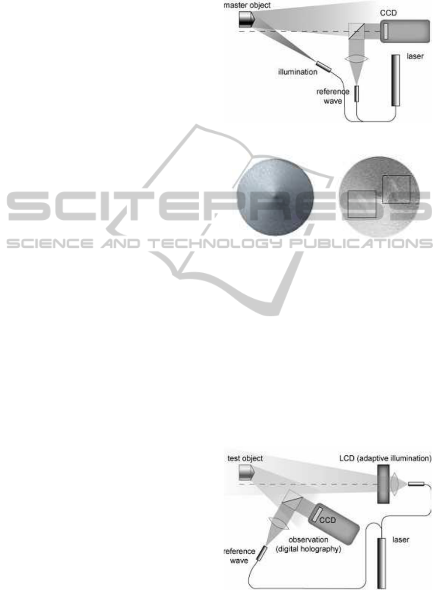
Figure 2: Recording of the coherent mask with the master
object.
(a) Master object (diameter 10
mm)
(b) Sample object with marked
dents
Figure 3: Master and Dented Sample Object.
deformation with those of a sample object having a
different microstructure:
• numerical comparison of the respective phase dis-
tributions of the relevant digital holograms or
• optical comparison of both interferograms by
Digital Comparative Holography.
In the case of a numerical comparison the differ-
ence phases of the master object and the sample object
are subtracted directly in the computer. This results in
the elimination of the basic shape of the object and the
enhancement of differences between the two objects.
In case of the optical technique the digital interfer-
ogram of the master object has to be reconstructed
Figure 4: Coherent illumination of the sample by the con-
jugated wavefront of the master.
CLOSER2013-3rdInternationalConferenceonCloudComputingandServicesScience
376
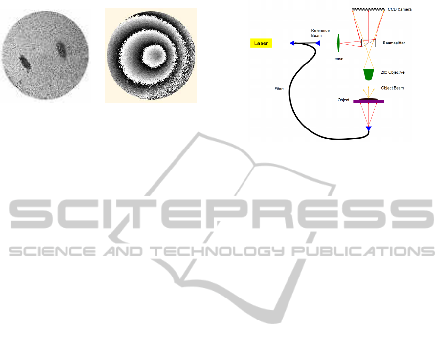
(a) Result of the coherent illumina-
tion with the conjugated wavefront
of the master
(b) Result of conventional two-
wavelength contouring
Figure 5: Shape comparison between a master and a sample
object by comparative digital holography.
by a suitable spatial light modulator such as a liquid
crystal SLM or a digital micro mirror device. Fig. 2
shows the setups for recording the master-hologram,
Fig. 4, and for investigating the sample/test object by
the comparative technology, Fig. 3(b). For that pur-
pose the sample object is coherently illuminated by
the conjugated wavefront of the master object. To re-
construct the conjugated wavefront of the master the
master-hologram is written to the SLM and the SLM
is illuminated by the conjugated reference wave that
was used for making the master-hologram. This 2step
procedure leads to an interferogram of the sample that
indicates only the difference in shape or deformation
between master and sample, Fig. 3 and Fig.5 . In our
example the objects to be compared are two macro-
scopically identical aluminum cylinders with a cone
at their upper end, Fig. 3(a). One of the cylinders
has 2 small dents of some micrometers in the cone,
Fig. 3(b). For the experiment a synthetic wavelength
of = 0,326 mm was adjusted by the two single ex-
posures with 1=579,41 nm and 2=580,44 nm. Due
to the holographic illumination of the sample with
the conjugated wavefront of the master the indicated
difference phase (P) corresponds directly to the dif-
ference of the height deflections between master and
sample in every object point. Consequently, the reg-
istered phase distribution indicates only the deviation
between master and sample, Fig. 5(a). The size of
the detected deviations depends as well on the reso-
lution of the used SLM and CCD, and the size of the
synthetic wavelength. In the described experiment we
detected height deviations of several 10 microns. Us-
ing the SLM, misalignment between the master and
the sample can be compensated by a corresponding
phase shift of the reconstructed master wavefront. A
comparison of Fig. 5(a) with Fig. 5(b), the result of
conventional holographic contouring, shows the ad-
vantage of Comparative Digital Holography for shape
comparison: only the difference in shape of two nom-
inally identical objects with various microstructure is
Figure 6: Experimental setup of the digital holographic mi-
croscopic system.
displayed. The high level of noise is justified by the
relatively large pixel size of the used LCD-modulator
compared to the available CCD-sensor (CCD 9m,
LCD 18m).
2.2 Digital Holographic Microscopic
System
In this section we describe the functional implementa-
tion of the architecture, focusing mainly on the setup
of the holographic system and the configuration of the
remote control (i.e. the components in the box on the
right in Fig. 7). The experimental setup of the digital
holographic microscopic system is shown in Fig. 6. A
laser beam of is first coupled into a fiber and subse-
quently divides into a reference arm and object arm.
The object arm fiber can be switched for different il-
lumination modes, i.e., transmission mode or reflec-
tion mode, depending on the property of the object
to be investigated. The object is imaged through a
20x/0.5 microscopic objective. The reference beam is
coupled into the system using a beam splitter, to in-
terfere with the object wave. The sample is mounted
on an electric-driven 3D positioner (Physical Instru-
ment), allowing the user to shift the field of view at
sub-micron precision. A CCD camera (SVS16000)
records the hologram and transfers the data to the
computer for sbsequent processing. The camera has a
large sensing area of 43.3 mm diagonally with 16 M
(4896× 3280) pixels of 7.4× 7.4 microns in size. The
provides a transmitting rate of as high as 1 gigabit per
second, with effective frame rates of 3f ps. It is con-
nected to the host computer through a PCI(e) network
interface card with 82541 chip set (for example, In-
tel Pro/1000 GT PCI card in our case) using an RJ45
network cable.
Reconstruction of the object wave is performed
numerically. The intensity pattern f(ξ, η) recorded
is first filtered in the spatial Fourier-Domain(M. et al.,
RemoteLaboratoriesintheCloud-ADigitalHolographicMicroscope
377
1982) , removing the DC component and the conju-
gate twin image in the reconstruction. The filtered
signal is inverse Fourier transformed and then propa-
gated and focused in the object plane (x, y) at distance
z using the Fresnel transformation T (z) (approxima-
tion of the wave propagation for distances z ≫ λ)
g(x, y, z) :=
exp(ikz)
iλz
Z
∞
−∞
Z
∞
−∞
f(ξ, η) ·
· exp(
ik
2z
((x− ξ)
2
+ (y− η)
2
))dξdη
= T (z)( f(ξ, η))
The whole reconstruction process can thus be ex-
pressed as
g(x, y, z) := T (z)(F
−1
(h(F ( f(ξ, η)))))
where F denotes the Fourier-Transform and h the
spatial filtering in the Fourier-Domain.
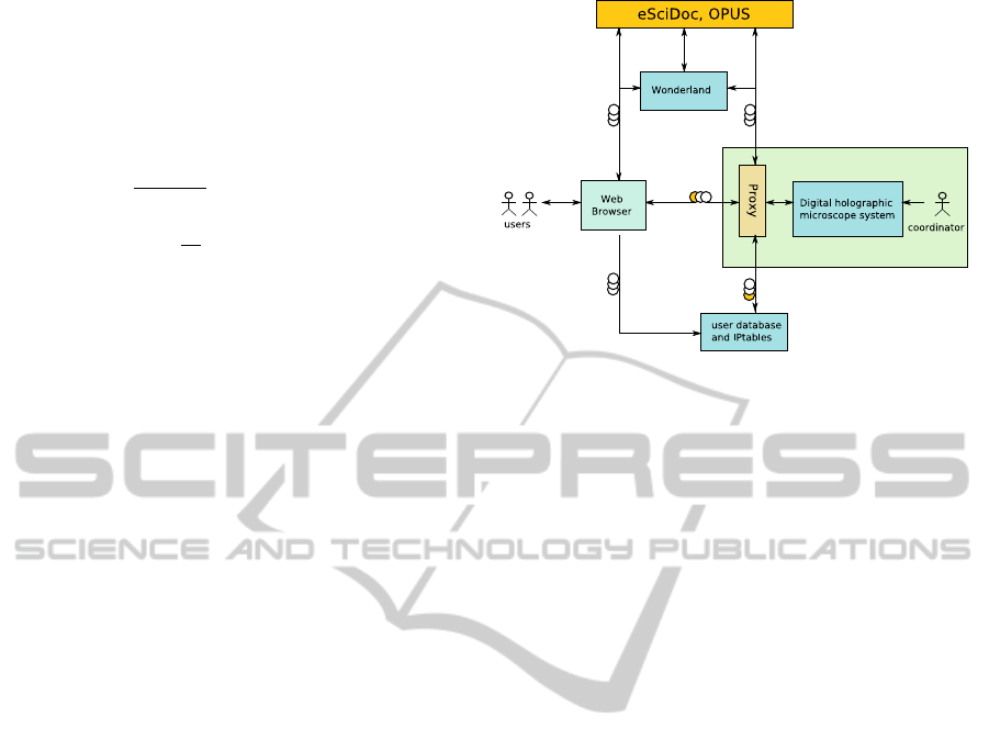
3 SYSTEM ARCHITECTURE FOR
THE HOLOGRAPHIC
MICROSCOPy
The system architecture for the remote lab is schemat-
ically shown in Fig. 7. At the heart of the archi-
tecture is the digital holographic microscopic system,
which is hidden behind a proxy server and can be ac-
cessed directly only by an operator at our institute.
The computer running the software necessary for con-
trolling the physical experiment is invisible from the
outside. All outside contact is handled by the proxy
server, using an SSH tunnel for encrypted, secure data
exchange. Users access the experiment through the
BW-eLabs portal, which authenticates against an eS-
ciDoc user data base. On successful authentication,
an SSH tunnel is opened to the SSH server running
on the proxy, with authentication passed on using
PAM (“pluggable authentication modules”). eSciDoc
also provides storage and access to experimental data,
passing data for automatic configuration of the exper-
iment, and access to the publication infrastructure of
OPUS(Opu, ) . From the user’s perspective, the func-
tionality of eSciDoc is mostly transparent, working
automatically in the background. The coordinator has
to provide a script defining the data, format and meta-
data to be stored. The actual storage process and the
corresponding retrieval process is fully symmetrical,
allowing not only access to raw data for analysis, but
also to restore the complete state of the experimen-
tal setup (e.g. in our case, the position of the ob-
ject under investigation, the focusing of the micro-
scope, the parameters requires in the reconstruction
Figure 7: Schematic architecture for the remote experimen-
tal system.
of the hologram). eSciDoc is accessible by generic
users, providing search functionality based on meta-
data generated during the experiment. The roles and
rights of users in eSciDoc are rather complex and can
be set individually for each experimental set-up and
each set of data (if desired), protecting against unde-
sired third party access while enabling collaboration
between privileged partners.
3.1 Setup of the Remote Controlling
System
Many techniques can be used for remote controlling.
The choice for our project, Virtual Network Com-
puting (VNC) used by MIT (Selmer et al., 2007) al-
lows in principle for complete control of a host com-
puter by a remote client. While somewhat slower and
very open compared to alternatives like “LabVIEW
Remote Panel” (lab, ) (LRP) developed by National
Instruments Inc, it offered some fundamental advan-
tages within the framework of the project as a whole.
VNC can connect through a proxy using an SSH tun-
nel, adding standard authentication through PAM and
encryption for security, based on existing software
such as Java-Portlets running on the BW-eLabs Portal
server and Python modules on the proxy server. As
a result, authentication is left very flexible and does
not require local accounts, any number of different
authentication methods are possible (e.g. the whole
system, including eSciDoc, could authenticate against
a trusted identity provider using Shibboleth (Shi, ) or
similar). The second argument for VNC was the easy
integration of proprietary software for remote control,
an aspect vital in future expansions of the project.
Any existing remote control can be easily integrated
into BW-eLabs through VNC, shifting the focus of
development to the interaction with eSciDoc for auto-
CLOSER2013-3rdInternationalConferenceonCloudComputingandServicesScience
378
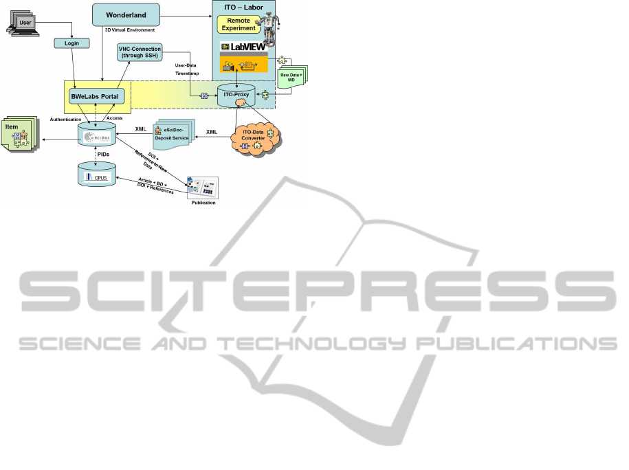
Figure 8: Architecture and Components for the Remote
Laboratory.
matic storage and access to experimental data.
The major advantage of this setup lies in the min-
imal effort demanded from the provider of the ex-
periment. User authentication, secure connection,
user management, scheduling of experiments, stor-
age, publication and retrieval of data are all provided
by the infrastructure and can be located anywhere, ei-
ther on specific systems or within the cloud (although
the publication process does require long-term acces-
sibility to the stored data, though not necessarily on
the same, permanent location).
3.2 Data Flow and Integration into the
Infrastructure
Fig. 8 shows a schematic representation of the data
flow within BW-eLabs, with the remote controlled ex-
periment described above being represented in the up-
per right corner and the connection through the BW-
eLabs portal using VNC in the center. This section
will be concerned with the integration into the infras-
tructure, mainly, the connection to the eSciDoc repos-
itory.
The data transfer between the experiment and eS-
ciDoc is very generic. A daemon (a small program
running continuously in the background) called eS-
ciDoc Deposit Service is installed on the controlling
computer and adapted to watch a specific directory. If
a file is written to this directory, it will be automati-
cally copied and send to a specified eSciDoc instance.
In the transfer process the data is extended with cer-
tain metadata, including, but not limited to:
• Description of the experiment and the object un-
der investigation (maunally created by the experi-
menting scientist)
• Parameters describing the physical state of the set-
up, including positioning of the object, focusing
of the microscope, a blind measurement needed
to compensate for the curvature of the reference
wave in the phase reconstruction (generated auto-
matically by the controlling LabView program)
• Parameters needed in the analysis and interpreta-
tion of the raw data, in our case a description of
the laser (type, wavelength), optical path length
for the Fresnel reconstruction, filter parameters
used in the Fourier domain, algorithms used etc
(generated automatically by the controlling Lab-
View program)
• Administrative metadata, specifying institution,
project, investigation, measurement series and
similar (usable in billing, parts created automat-
ically in eSciDoc).
• Time stamp and user id (created automatically in
eSciDoc).
This metadata serves in support of semantical search
as well as in restoring a specific, physical state of
the experimental setup or in the numerical analysis
and interpretation of raw data (in our case, the re-
construction of the hologram and the measured defor-
mation of the object). The first three types of meta-
data are laboratory-specific and have to be defined in
a Python/Perl/shell script (see below). The last two
generated automatically by eSciDoc.
The data itself can be anything, ranging from raw,
binary data to complex structured data. Transfer to
eSciDoc is performed using HTTP. On the eSciDoc
server, the data is passed on to an eSciDoc depository
service that in turn calls a pre-defined script (Ito Data
Converter) to build an eSciDoc item, consisting of
raw data and XML metadata. These items are stored
in eSciDoc, with the metadata being used for index-
ing search functionalities. Loading an item is again
performed using HTTP, with the returned data being
identical to that originally saved. The whole process
is completely symmetrical and transparent for the user
performing the experiment.
eSciDoc provides a multitude of functionalities to
handle experimental data, ranging from hierarchical
organization of datasets into projects, versioning and
even “publication” through the assignment of a per-
sistent identifier like a DOI. Upon publication, the
DOI marked data set can be published on the OPUS
document server utilized by several German public
and university libraries.
4 CURRENT RESULTS AND
FUTURE WORK
Figure 9 shows the frontpanel of the LabView VI
RemoteLaboratoriesintheCloud-ADigitalHolographicMicroscope
379
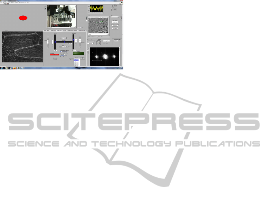
Figure 9: The current Labview front panel, showing a sam-
ple of onion cells.
(“Virtual Instrument”, the LabView term for a pro-
gram) with the image of a webcam showing the phys-
ical setup on the top left, with the numerically recon-
structed hologram, in this case, a biological sample,
onion cells, on the far right. The hologram was fil-
tered in the spatial Fourier-Domain previous to re-
construction (M. et al., 1982) , removing the DC
component and the twin image in the reconstruction
to improve the utilization of the spatial bandwidth
of the camera. The other two display below show
the phase retrieved from the hologram and the phase
difference between the currently investigated holo-
gram and a reloaded, previously recorded hologram
for comparativemetrology. Phase unwrapping (Hunt-
ley, 2001; Ghiglia and Romero, 1994; Ghiglia and
Romero, 1996) provides a 3D reconstruction of the
deformation of the object, displayed on the bottom
left.
The dials control the set-up, move the stepper mo-
tors of the 3D positioner and select a region of inter-
est for the numerical reconstruction of the hologram.
One useful feature and used to demonstrate the inter-
action with eSciDoc is the “save current position” and
the “restore saved position” buttons. The position of
the positioner is stored in an XML file and restored,
positioning the system in the original configuration.
This function is very useful in bringing a given region
of a sample back into focus, an otherwise slow and
tedious process, since the full reconstruction of the
hologram takes a couple of seconds.
The current implementation includes the actual
experiment, the controlling LabView software, the
VNC connection and the login through the BW-eLabs
server. The next steps in the ongoing work of this
project will consist of the connection to the eSciDoc
system, saving and loading data into the repository
and in the integration of the system into a virtual 3D
world, first as a simple solution displaying the VNC
interface within the 3D environment, then in a more
direct manner, controlling the LabView VI directly
from and displaying the recorded holograms directly
within virtual world.
While some provisions have been made towards
access to the laboratory from the cloud, additional
work is required. Authentication and access to the set-
up are flexible enough to accommodate access from
the cloud, as long as they are connected to a specific
eSciDoc instance. eSciDoc itself is quite flexible in
the location of its data, so could be adapted to use
a DaaS paradigm, as long as long-term access to the
data is guaranteed for the DOIs. Analysis of the data
can be either performed remotely on the lab computer,
or, given an installation of the proper LabView VI,
within the cloud under the SaaS paradigm, retrieving
the data from the eSciDoc storage.
5 CONCLUSIONS
We have shown a possible extension of the cloud
computing concept by adding real-world facilities to
the cloud. The facilities are embedded in a remote
laboratory that provides the complete infrastructure
for the remote access and data exchange. Such a
system opens up many novel opportunities in indus-
trial inspection such as the remote master-sample-
comparison and the virtual assembling of parts that
are fabricated at different locations. Moreover, a mul-
titude of new techniques can be envisaged, among
them advanced approaches to documenting, efficient
methods for metadata storage, the possibility for re-
mote reviewing of experimental results, the adding
of real experiments to publications by providing re-
mote access to the metadata and to the experimental
setup via Internet by simply quoting the uniform re-
source locator in the reference list, the presentation of
complex experiments in classrooms and lecture halls,
the sharing of expensive and complex infrastructure
within international collaborations, the implementa-
tion of new ways for the remote test of new devices,
for their maintenance and service, and many more.
However, there are still several problems that have to
be solved before the full potential of the remote labo-
ratory approach can be realized. Among these is the
need for the clarification of a series of legal questions
such as IP rights, the definition and agreement of stan-
dards (protocols, 3D-user interfaces, data structures,
data archiving, ...), and last but not least the conven-
tion and implementation of safety standards for the
remote access to the infrastructure (the continuous
availability, the facility and personal protection, the
access rights and authentication).
CLOSER2013-3rdInternationalConferenceonCloudComputingandServicesScience
380

ACKNOWLEDGEMENTS
This work was funded by the Ministerium f¨ur Wis-
senschaft, Forschung und Kunst Baden-W¨urttemberg
under the project BW-eLabs.
REFERENCES
http://code.google.com/intl/de-DE/appengine/.
http://aws.amazon.com/de/ec2/.
http://docs.google.com/.
http://zone.ni.com/devzone/cda/tut/p/id/4791.
http://openwonderland.org/.
https://www.escidoc.org/.
http://www.opus-repository.org/index.html.
http://shibboleth.internet2.edu/.
Amburst, M., Fox, A., Griffith, R., Joseph, A. D., Katz,
R. H., Konwinski, A., Lee, G., Patterson, D. A.,
Rabkin, A., Stoica, I., and Zaharia, M. (2009). Above
the clouds: A berkeley view of cloud computing.
Technical Report No. UCB/EECS-2009-28, Electri-
cal Engineering and Computer Sciences, University of
California at Berkeley.
Baumbach, T., Osten, W., von Kopylow, C., and J¨uptner,
W. (2006). Remote metrology by comparative digital
holography. Appl. Opt., 45:925–934.
Chang, F., Dean, J., Ghemawat, S., Hsieh, W. C., Wallach,
D. A., Burrows, M., Chandra, T., Fikes, A., and Gru-
ber, R. E. (2006). Bigtable: A distributed storage sys-
tem for structured data. In Proceedings of the 7th con-
ference on usenix, Symposium on operating system de-
sign and implementation, volume 7, pages 205–218.
F¨uzessy, Z. and Gyimesi, F. (1984). Difference holographic
interferometry: Displacement measurement. Optical
Engineering, 23(6):236780–236780.
Ghiglia, D. C. and Romero, L. A. (1994). Robust two-
dimensional weighted and unweighted phase unwrap-
ping that uses fast transforms and iterative methods. J.
Opt. Soc. Am. A, 11(1).
Ghiglia, D. C. and Romero, L. A. (1996). Minimum lp-
norm two-dimensional phase unwrapping. J. Opt. Soc.
Am. A, 13(10).
Huntley, J. (2001). Digital Speckle Pattern Interferometry
and Related Techniqus, chapter Automated Analysis
of Speckle Interferograms, pages 108–121. John Wi-
ley & Sons, LTD.
Jeschke, S., Hauck, E., Kr¨uger, M., Osten, W., Pfeiffer, O.,
and Richter, T. (2011). Networking resources for re-
search and scientific education in bw-elabs. In Au-
tomation, Communication and Cybernetics in Science
and Engineering 2009/2010, volume Part 2, pages
241–258.
Kemper, B. and von Bally, G. (2008). Digital holographic
microscopy for live cell applications and technical in-
spection. Applied Optics, 47(4).
Kohler, C., Schwab, X., and Osten, W. (2008). Optimally
tuned spatial light modulators for digital holography.
Appl. Opt., 45:960–967.
K¨uhn, J., Montfort, F., Colomb, T., Rappaz, B., Moratal,
C., Pavillon, N., Marquet, P., , and Depeursinge1, C.
(2009). Submicrometer tomography of cells by mul-
tiplewavelength digital holographic microscopy in re-
flection. OPTICS LETTERS, 34(5).
Langehanenberg, P., Kemper, B., and von Bally, G.
(200y). Autofocus algorithms for digital-holographic
microscopy. In Popp, J. and von Bally, G., editors,
Biophotonics 2007: Optics in Life Science, Proc. of
SPIE-OSA Biomedical Optics, volume 6633. SPIE-
OSA.
M., T., Hideki., and S., K. (1982). Fourier-transform
method of fringe pattern analysis for computer-based
topography and interferometry. J. Opt. Soc. Am., 72.
Neumann, D. (1980). Comparative holography. In Tech.
Digest, Topical Meeting on Hologram Interferometry
and Speckle Metrology. Opt. Soc. Am.
Osten, W. (2000). Holography and virtual 3d-testing. In
Osten, W. and J¨uptner, W., editors, Proceedings of the
International Berlin Workshop HoloMet 2000, vol-
ume 14, pages 14–17, Bremen, Germany. Bremen In-
stitute of Applied Beam Technology.
Osten, W., Baumbach, T., and J¨uptner, W. ((2001)). A new
sensor for remote interferometry. In SPIE, volume
4596, pages 158–168.
Osten, W., Baumbach, T., and J¨uptner, W. (2002). Compar-
ative digital holography. Opt. Lett., 27:1764–1766.
Rastogi, P. K. (1984). Comparative holographic moire in-
terferometry in real time. Appl. Opt., 23(6):924–927.
Razum, M., Schwichtenberg, F., Wagner, S., and Hoppe,
M. (2009). escidoc infrastructure: A fedora-based e-
research framework. In et al., M. A., editor, ECDL,
volume 5 2009, LNCS 5714, pages 227–238.
Sainov, V. and Simova, E. (1989). Comparative holographic
moire interferometry: Separation of moire fringes
from the carrier interference pattern. Optical Engi-
neering, 28(5):285550–285550–.
Schnekenburger, J., Bredebusch, I., Langehanenberg, P.,
Domschke, W., von Bally, G., and Kemper, B. (2007).
Dynamic in vivo analysis of drug induced actin cy-
toskeleton degradation by digital holographic mi-
croscopy. In Popp, J. and von Bally, G., editors, Bio-
photonics 2007: Optics in Life Science, Proc. of SPIE-
OSA Biomedical Optics, volume 6633. SPIE-OSA.
Selmer, A., Kraft, M., Moros, R., and Colton, C. K. (2007).
Weblabs in chemical engineering education. Trans.
IChemE Part D, 2.
Wang, L., Tao, J., Kunze, M., Castellanos, A. C., Kramer,
D., and Karl, W. (2008). Scientific cloud computing:
Early definitions and experience. In 10th IEEE Inter-
national Conference on High Performance Computing
and Communications, 2008. HPCC ’08., pages 825–
830.
RemoteLaboratoriesintheCloud-ADigitalHolographicMicroscope
381
