
Domain Controlled Architecture
A new approach for Large Scale Software Integrated Automotive Systems
Dominik Reinhardt
1
, Markus Kucera
2
1
BMW AG, Munich, Germany
2
University of Applied Science Regensburg, Germany
Keywords:
Large Scale Software Integration: LSSI: Automotive Real Time: Multi-Core: Many-Core: Embedded
Automotive Software Architecture
Abstract:
Electric and electronic functionalities increase exponentially in every mobility domain. The automotive in-
dustry is confronted with a rising system complexity and several restricting requirements and standards (like
AUTOSAR), in particular to design embedded software for electronic control units. To stand against rampant
functionalities software units could be restructured according to their affiliation and should not be attached to
a certain place. This can be effected by integration on single controllers. On the one hand the system wide
amount of hardware controllers could such be limited. On the other hand the workload for integration CPUs
will rise. To support this paradigm, multi-core systems can provide enough processing power in an efficient
way. This paper shows a first approach to combine automotive functionality on such a single controller.
1 INTRODUCTION
E/E (Electric/Electronic) systems represent an impor-
tant part in premium vehicles and are the major con-
tributor in creating added value for OEMs (Original
Equipment Manufacturer). The amount of vehicle
functions increases exponentially and functionalities
get more and more complex. This trend is tightened
by additional requirements like lightweight design
and construction, energy efficiency, functional safety
driven by the new ISO standard for road vehicles, and
last but not least by the development standard (AU-
TOSAR Administration, 2012) for automotive soft-
ware architecture AUTOSAR (AUTomotive Open Sys-
tem ARchitecture).
Facing increasing software workload and rising
need for SW/HW robustness, there is a need for more
powerful hardware resources. Furthermore, the num-
ber of ECU (Electronic Control Unit) devices must
be reduced (Gut et al., 2012). To save fuel and extend
the crusing range of electric cars, the power consump-
tion of embedded systems and in detail of electronic
semiconductors shall be minimized (Sch
¨
ottle, 2012),
(Barthels et al., 2012). The actual state-of-the-art
in science and technology (Arbeitskreis-Multicore,
2011) shows that multi-core technology can solve the
problem in a more efficient way. Ten years ago Gor-
don Moore’s Law (Moore, 1965) was contested in the
area of consumer electronics and multi-core proces-
sors were published for general public on the market.
High performance computing systems or even mobile
devices like smart phones cannot get along without
this technology to supply the requests of processing
power. This paradigm has reached the automotive in-
dustry eventually (Schneider et al., 2010) and (Monot
et al., 2010).
Dual- or quad-core systems are already available
on the market for vehicle manufacturers. In the fu-
ture this trend will be continued and the amount of
cores will rise. Many-core controllers could revolu-
tionize current development standards and strategies.
For automotive systems it is not yet completely solved
how to obtain more and more speedup with a rising
number of cores and in comparison with small but
computationally intensive, high interconnected appli-
cations. For every single vehicle function built for
domains like chassis or powertrain it is to clarify,
how to segregate them from each other and how to
achieve given constraints in time or space. According
to Amdahl’s (Amdahl, 1967) and Gustafson’s Law
(Gustafson, 1988), to optimize the systems speedup,
software modules with less dependencies to units lo-
cated on other cores can be parallelized more effi-
ciently on probably more than 16 cores. This fact
will challenge automotive software engineers to re-
view former development techniques and design rules
Reinhardt D. and Kucera M..
Domain Controlled Architecture - A New Approach for Large Scale Software Integrated Automotive Systems.
DOI: 10.5220/0004340702210226
In Proceedings of the 3rd International Conference on Pervasive Embedded Computing and Communication Systems (PECCS-2013), pages 221-226
ISBN: 978-989-8565-43-3
Copyright
c
2013 SCITEPRESS (Science and Technology Publications, Lda.)

in order to create loose coupled systems and still ful-
fill the required functionality at once.
2 TODAY’S VEHICLE
COMMUNICATION
ARCHITECTURES
To improve an automotive E/E system to deal with
gaining vehicle functionalities it is modified by a top
down approach. At first the vehicle electrical system
architecture must be fitted to be flexible enough to get
along with future upgrades and modifications. There-
fore, the integration of vehicle functions to ECUs has
to be reconsidered. In the following the actual de-
centralized communication network of BMW is com-
pared with a future centralized architecture approach.
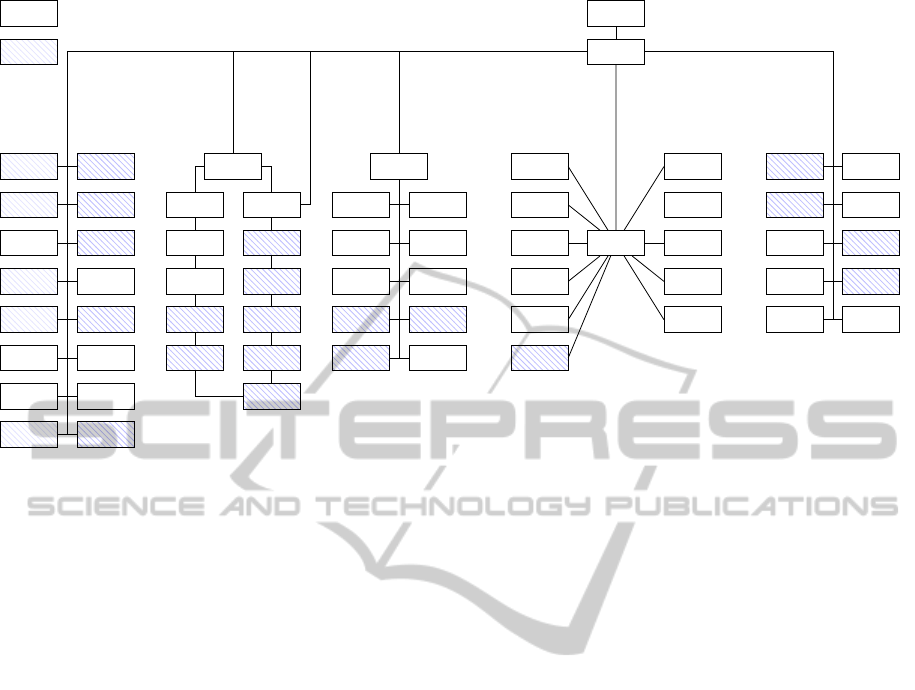
2.1 Present decentralized vehicle system
architecture
Actual embedded vehicle functions are shared be-
tween up to 70 electronic control units and are con-
nected over several buses (see Figure 1). Evoked by
this fact, electrical vehicle functions, which are ac-
counted on the OEM side, are developed by several
suppliers. Certainly it is easier to separate these prob-
lems to a manageable amount of ECUs, at least to
solve the final problem to integrate the system onto
an ECU. In present the main advantage not to over-
load the systems functionality and having a structured
software architecture overview causes less prices for
software developing and single hardware platforms.
According to the shared geometric assembly of ECUs
inside of the car transmission paths or rather the cable
runs to sensor and actuator components are shortened.
In terms of lifetime, it is easier to exchange damaged
parts if E/E components are lightweight and do not in-
clude most of the vehicles software functionality. In
detail, a shared HW/SW architecture gives persons in
charge a better control of their encapsulated system
and enhances robustness for installing later software
updates. At the end, the system is more scalable and
could be flexibly adjusted from start until end of pro-
duction of a vehicle product line.
On the one hand, decentralized systems provide
a high amount of flexibility related to loose coupled
hardware components networked within the vehicle
bus architecture. On the other hand, this flexibility in-
creases the system price due to a lot of overhead. Be-
cause of the rising communication demand between
software components, some vehicle buses could get
overloaded and would not be able to stand the volume
of signals and information any more. Due to the sys-
tem complexity, there are many masked problems like
interference with communications between ECUs and
their integrated software components. If no common
interfaces exist, intra ECU communication will cause
a lot of problems.
2.2 BMW’s approach for future
centralized system architecture
designs
Centralized car functions implicate a single source
of information which can be processed internally by
ECU and advanced function comprehensive calcula-
tions. Functions shall be clustered in a single place.
A decreased number of ECUs implies the reduce of
internetworking complexity and saves costs for car
wiring harness which is probably one of the most de-
termining factors. Due to the joint software integra-
tion on an ECU, timing constraints can be achieved
more easily in matters of integration time, if no slow-
ing transportation layer must be passed through. De-
pending of ECU capability and system architecture,
perceived events, like video camera signals, can be
evaluated much faster if the processing of signal in-
put, decision and output is located in a single system.
Nevertheless, the physical connection to most of the
actuators and sensors still has to exist. Relocating the
software responsibility on single ECUs is associated
with additional disadvantages. An obvious problem is
the need of a capable hardware controller which can
deal with the rising workload. It implies acquiring ex-
pensive hardware platforms. In the case of damage,
a valuable component must be replaced. This im-
pedes the handling of oversized systems in question
of scalability and flexibility and hence poses further
disadvantages. If applicable from a safety perspective
it means a loss of redundancy which must be solved
compliant to automotive standards.
For common hardware and software systems there
are many terms and definitions for the method to con-
sciously centralize components (e.g. High Integra-
tion, Highly Integrated Software, Very Large Scale
Integration, High Density Integration). However,
each of those do not fit to the presented require-
ments. Therefore we introduce the term ’Large Scale
Software Integration’ (abbr. LSSI), according to the
already common used term Very Large Scale Integra-
tion. Enriched by the word ’software’, it emphasizes
our site of operation. A LSSI system centralizes sev-
eral high integrity vehicle software components onto
a single ECU. To avoid interference with others, soft-
ware components have to be isolated.
Standard
Equipment
Additional
Equipment
Anti-Theft
Alarm
1 Axes Air
suspension
Center
Console
Tyre Pres-
sure Control
Rain Sensor
Light Switch
Module
Heater
Control
Heater oper-
ation front
Trailer
Module
Park Dis-
tance Cont.
Center Con-
sole front
Chassis
Integration
Sunroof
Wiper
Module
Controller
Auxilary
Heating
Human Ma-
chine Interf.
Audio Sys-
tem Cont.
Antenna
Tuner
Video
Module
Navigation
System
Amplifier
Kombi
Instrument
Multi-Media
Changer
Audio-CD
Changer
Headset
Interface
Speech In-
put System
Telephone
Interface
Car Access
System
Door Modu-
le Driver
Door Modu-
le Driver B
Seat Module
Driver
Seat Module
Driver Back
Back
Door Lift
Door Mod.
Ass. Driver
Door Mod.
Ass.Driver B
Seat Module
Ass. Driver
Seat Module
Ass.Driver B
Seat Back
Diagnostic
Access
Central
Gateway
Security/Info.
Module
Vehicle Cen-
ter Module
A Col-
umn Left
B Col-
umn Left
Driver Seat
Front
Left Door
Rear Seat
Bench
Central
Steering Col.
A Column
Right
B Column
Right
Assistant
Driver Seat
Front
Right Door
Adaptive
Cruise Cont.
Active Roll
Stabilization
Dyn. Stabi-
lity Cont.
Elect. Gear-
box Cont.
Elect. Hand
Brake
Digital Mo-
tor Cont.1
Digital Mo-
tor Cont.2
Adaptive
Light Cont.
Elect. Dam-
per Control
Rotation
Rate Sensor
K-CAN System
MOST
K-CAN Peripherals ByteFlight
PT-CAN
Figure 1: Decentralized ECUs of a example vehicle electrical system architecture (Barthels et al., 2012), (Michel et al., 2012)
3 POSSIBLE REALIZATION OF A
DOMAIN CONTROLLED
AUTOMOTIVE SYSTEM USING
MULTI-CORE CPUS
Facing the consistently growing amount of car fea-
tures, which are attended by rising software complex-
ity, vehicle electrical systems need to be restructured
and more flexible architecture patterns must be estab-
lished. Until now vehicle functions have been dedi-
cated to a certain controller.
In a domain controlled architecture, ECUs and in
special corresponding E/E vehicle functionality shall
be oriented in a domain specific manner. Typical
domains are Infotainment, Chassis, Powertrain and
Body and Comfort (Michel et al., 2012). To reach
a higher level of system scalability, an additional ab-
straction layer, in the form of capable server ECUs
called domain controllers (compare with Figure 2), is
established for each special domain. Every domain
controller can control several field bus systems. To
save energy (Sch
¨
ottle, 2012), connected network clus-
ters can be deactivated individually to allow a partial
bus operation (Fuchs et al., 2010). Furthermore, do-
main controllers are used as integration platform for
system software components. Applications, which
must always be available during car usage are inte-
grated on these ECUs. In general domain controllers
contain OEMs specific software components. Beside
others, these servers act like routers and are responsi-
ble to regulate the activity for their affiliated sub do-
main ECUs. These slave controllers in contrast are
light and flexible for operation. Typically commod-
ity functions like the airbag system will be integrated
on them, which imply a more flexible partitioning in
different locations.
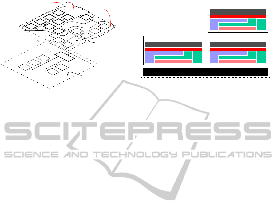
3.1 Domain driven partitioning of
software components within the
vehicle communication network
The software components unity is analyzed from a
logical side of view to reorder E/E functions within
the vehicle electrical system (see Figure 2). Appli-
cations which were sorted according to their specific
domain are sliced and integrated on a domain or sub
controller. Thereby located units, which are corre-
lated to their neighbors, form a closed composition.
The path of information between software compo-
nents shall be as condensed as short as possible. This
paradigm brings new requirements for software archi-
tectures and interface designs to dissolve strong cou-
pled applications and system functionality. Measured
by their lines of code, automotive E/E functions are
typically small applications. Therefore, it is hard to
split associated software components and share them
VF VF VF
VF VF VF
VF VF VF
VF
VF VF
VF
VF VF
Domain
Controller
Sub A Sub D
Sub B Sub D
Sub C
Technical View
Logical View
Vehicle Functions parti-
tioned for a Sub Controller
Vehicle Functions partitioned
for a Domain Controller
Figure 2: Logical segmentation of an vehicle electrical sys-
tem structure
on several ECUs. To gain the best SpeedUp in spite
of achieving all applications requirements, the chal-
lenge therein is to develop the optimal allocation for
software components. It has to be balanced if vehicle
E/E software functions are to be entirely integrated on
a domain controller, or on a sub domain ECU, or are
split up to work partly on each of them.
The architectural design has to be flexible in such
a way that E/E feature’s expansion stage is alterable
to the related car. To guarantee a flexible operation,
software components are developed in a loose cou-
pled way to be mixable and individually integrated
on a single ECU. The isolation of these components
from each other will pose another challenge if they
are classified as safety-relevant. At all points, it must
be secured within large scale software integrated sys-
tems, that no installed application interferes with oth-
ers during runtime and manipulates not related data.
Given that a lot of software components will be ex-
ecuted on a domain controller, the workload is high,
and ECUs with sufficient performance are necessary.
Besides, to supply the required computing capacity
by using a power efficient hardware we propose to use
multi-core technology. To waste no additional energy,
efficient algorithms and protocols must be developed.
The calculation capacity of on-chip integrated cores
shall not be utilized of inter core communication or
task synchronization overhead.
3.2 Proposed static ECU allocation
integrated on closed cores
To deal with a multi core system, nearly the whole
integrated software must be completely restructured
and optimized for parallel processing (Akhter and
Roberts, 2006). In a large scale software integrated
ECU, composed of multiple self-contained software
projects, there will be typically loose coupled soft-
Microcontroller (µC)
Multicore
Electronic Control Unit
Core1: AUTOSAR 4.0
Core0: AUTOSAR 4.0 (safety critical)
Core2: AUTOSAR 3.1
Figure 3: Possible core partitioning adapted for independent
ECU projects
ware units. Beside components with high dependency
to related functionalities (like former master and slave
architecture constructs), lots of car software compo-
nents exist with less or even no connection to their
neighbors. Rearranging and integrating these units on
an ECU is not too challenging from an architectural
perspective. Because of their independence to each
other, such an architecture pattern represents an em-
barrassingly parallel problem (Foster, 1995). If het-
erogeneous software components run on an embed-
ded multi-core system, shared on several cores, they
probably offer the best benefit because there are no se-
quential parts to execute. To integrate non related sys-
tems on different cores dissolves the former bin pack-
aging problem to efficiently migrate as much soft-
ware components as possible on a single core machine
and to deal with hundreds of synchronous and asyn-
chronous tasks concurrently. To realize decoupled
system behavior, hardware resources are split up be-
tween any system and core (Hilbrich, 2012), (Brew-
erton et al., 2012).
Efficient ECU partitioning could give an impulse
for future research projects. Advancing further mi-
gration strategies on the one hand and support for
functional safety for orthogonal automotive software
systems on the other hand. As pictured in Figure
3, even software projects using different AUTOSAR
versions or Automotive Safety Integrity Levels (In-
ternational Organization for Standardization, 2011)
could be integrated. To realize an independent op-
eration, hardware resources must be separated. The
Memory Management Unit (abbr. MMU) or Mem-
ory Protection Unit (abbr. MPU) for instance must be
configured correctly to control the assigned Random
Access Memory of any core. Access problems will
occur if interfaces, like communication controllers,
are used simultaneously and therefore must be re-
served for usage exclusively.
Actually there are already isolated ECUs which

comprise a massive amount of car functionalities. An
example is the engine control unit which includes up
to 300 software components. It deals with lots of sen-
sor signals and is highly interconnected with other
controllers. However, on such a centralized software
system, some integrated functionalities are highly in-
volved with each other and are not suitable for fur-
ther relocation. Inter core communication will cause a
lot of overhead between cores or even between ECUs
if higher synchronization mechanisms have to han-
dle data exchange between every component. Be-
cause applications shall be shared individually be-
tween ECUs and cores this scenario could be an ori-
gin to fulfill the postulated requirements of a future
domain controller.
3.3 A standardized middleware for
domain controllers
Based on a technical side of view, every migrated sin-
gle core software project and their software compo-
nents run encapsulated on each core. Thus, the ap-
propriate Run Time Environment Layer (abbr. RTE)
must be located independently on every core, as well.
In practice, the upcoming bottlenecks are hardware
resources (e.g. memory and communication con-
trollers in all kinds), which have to be allocated si-
multaneously. These resources shall be under control
of centralized basic software modules, like the operat-
ing system, which handles each access. According to
the ISO Standard 26262 (International Organization
for Standardization, 2011), for safety-relevant vehicle
applications, which are specified with an ASIL, there
must be arrangements made to avoid any interference
caused by other components during runtime. The ap-
proach to run single core applications shared individ-
ually on multi-core core systems is covered from the
AUTOSAR 4.0 standard and is already included in its
basic software.
The AUTOSAR Operating System (abbr. OS) is
enriched by the new IOC (Inter-OS-Application Com-
munication), which allows information exchange be-
tween OS-Applications (AUTOSAR, 2011). There-
fore all information is passed through by the IOC (see
fig. 4). For software components, running on applica-
tion layer level, this module is not directly accessible
and is decoupled by the RTE (AUTOSAR Adminis-
tration, 2011). If information transfer between soft-
ware components shared on several cores is needed,
this feature is a possible approach for it. As proposed
in (Scheidemann et al., 2010a), (Scheidemann et al.,
2010b), the IOC enables the communication chan-
nel between separated memory partitions, surround-
ing software component groups which assure freedom
from interference related on memory faults. Thus, if
the MPU or MMU is configured correctly, software
components cannot modify memory of another par-
tition. Considering a multi-core scenario, the IOC
facilitates communication over core borders. How-
ever these mechanisms have an influence on the whole
system performance and availability. Especially for
safety-relevant functions, mixed integrated on a mul-
ticore controller with hard timing constraints, provi-
sions like appropriate scheduling algorithms have to
be arranged at software integration phase (Schmidt
et al., 2012), in order to guarantee the predicted ex-
ecution time of each software component.
4 CONCLUSION AND FUTURE
WORK
In the future, Tier-2 and also Tier-1 suppliers will
mainly supply and develop multi-core platforms for
OEMs. Car manufactures are confronted with the ac-
tual hardware controller designs and have to deal with
the problem to parallelize their software and to re-
duce complexity. More and more software compo-
nents must be integrated on less automotive ECUs.
If that assumption applies, large scale software inte-
gration techniques could be the enabler for upcom-
ing automotive E/E software architectures. As men-
tioned before, these approaches will come along with
multi-core hardware platforms, derived from con-
sumer electronics.
This paper proposes a domain controlled archi-
tecture in order to exhibit a possible approach for
future vehicle electrical systems. Furthermore, it is
demonstrated that there is a need for further research,
to transfer multi-core technologies to the automotive
industry, by using the examples of consumer elec-
tronics. Nevertheless, considering the different sys-
tem and safety requirements inflicted on mobility do-
mains, typical software parallelization scenarios, as
used for personal computer software, are not entirely
suitable. In this context, the national research project
ARAMiS aims at enabling multi-core systems for au-
tomotive, railway and avionic domain, to smooth the
way for Cyber Phyical Systems (Geisberger and Broy,
2012) in the future.
ACKNOWLEDGEMENTS
This work was funded within the project ARAMiS by
the German Federal Ministry for Education and Re-
search with the funding ID 01IS11035.
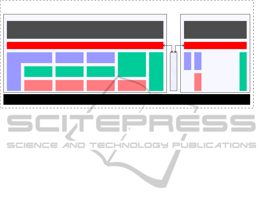
Multicore Electronic Control Unit
Core0 Core1
Application Layer Application Layer
Runtime Environment (RTE) Runtime Environment (RTE)
Service Layers
Memory
Services
Communication
Services
Onboard Device
Abstraction
Memory
Hardware
Abstraction
Communication
Hardware
Abstraction
I/O Hardware
Abstraction
Microcontroller
Drivers
Memory Drivers
Communication
Drivers
I/O Drivers
Complex Drivers
Microcontroller (µC)
Inter-OS-Application
Communicator
Operating
System
ECU State
Manager
Core Test
Complex Drivers
Figure 4: Inter core communication, using Inter-OS-Application Communicator
REFERENCES
Akhter, S. and Roberts, J. (2006). Multi-Core Program-
ming: Increasing Performance Through Software
Multi-threading. Books by engineers for engineers.
Intel Press.
Amdahl, G. M. (1967). Validity of the single processor ap-
proach to achieving large scale computing capabili-
ties. In Proceedings of the April 18-20, 1967, spring
joint computer conference, AFIPS ’67 (Spring), pages
483–485, New York, NY, USA. ACM.
Arbeitskreis-Multicore (2011). Relevanz eines Multicore-
¨
Okosystems f
¨
ur k
¨
unftige Embedded Systems. Techni-
cal report, BICCnet.
AUTOSAR (2011). Specification of Operating System.
Version 4.0.3 - Final.
AUTOSAR Administration (2011). Layered Software Ar-
chitecture - R4.0. Version 4.0.3 - Final.
AUTOSAR Administration (2012). AUTomotive Open
System ARchitecture. http://www.autosar.org.
Barthels, A., Michel, H.-U., and Walla, G. (2012). Jedes
Watt z
¨
ahlt - Intelligentes Energie- und Leistungs-
Management f
¨
ur die Autos von morgen. Elektronik
automotive, 05:24–28.
Brewerton, S. P., Willey, N., Gandhi, S., Rosenthal, T.,
Stellwag, C., and Lemerre, M. (2012). Demonstration
of Automotive Steering Column Lock using Multicore
AutoSAR
R
Operating System. In SAE International.
Foster, I. T. (1995). Designing and building parallel pro-
grams - concepts and tools for parallel software engi-
neering. Addison-Wesley.
Fuchs, M., Scheer, P., and Grzemba, A. (2010). Selektiver
Teilnetzbetrieb im Fahrzeug. In AmE 2010 - Automo-
tive meets Electronics. VDE-Verlag.
Geisberger, E. and Broy, M. (2012). agendaCPS: Integri-
erte Forschungsagenda Cyber-Physical Systems. acat-
ech Studie. Springer, Berlin.
Gustafson, J. L. (1988). Reevaluating amdahl’s law. Com-
mun. ACM, 31(5):532–533.
Gut, G., Allmann, C., Schurius, M., and Schmidt, K.
(2012). Reduction of Electronic Control Units in Elec-
tric Vehicles Using Multicore Technology. In Multi-
core Software Engineering, Performance, and Tools,
volume 7303, pages 90–93. Springer.
Hilbrich, R. (2012). How to safely integrate multiple appli-
cations on embedded many-core systems by applying
the ”correctness by construction” principle. Adv. Soft.
Eng., 2012:3:1–3:14.
International Organization for Standardization (2011). ISO
26262 Road vehicles - Functional safety - Part 1-10.
Michel, H.-U., Kaule, D., and Salfer, M. (2012). Vision
einer intelligenten Vernetzung. Elektronik automotive,
4:28–32.
Monot, A., Navet, N., Bavoux, B., and Simonot-Lion, F.
(2010). Multicore scheduling in automotive ECUs. In
Embedded Real Time Software and Systems - ERTSS
2010, Toulouse, France.
Moore, G. E. (1965). Cramming more components onto
integrated circuits. Electronics, 38(8):114–117.
Scheidemann, K., Knapp, M., and Stellwag, C. (2010a).
Load Balancing in AUTOSAR-Multicore-Systemen
Teil 1. elektroniknet, 1/2:22–25.
Scheidemann, K., Knapp, M., and Stellwag, C. (2010b).
Load Balancing in AUTOSAR-Multicore-Systemen
Teil 2. elektroniknet, 3:21–25.
Schmidt, K., Buhlmann, M., Ficek, C., and Richter,
K. (2012). Design patterns for highly integrated
ECUs with various ASIL levels. ATZ elektronik,
01/2012:22–26.
Schneider, J., Bohn, M., and R
¨
oßger, R. (2010). Migra-
tion of Automotive Real-Time Software to Multicore
Systems. In Proceedings Work-In-Progress Session of
the 22th Euromicro Conference on Real-Time Systems,
ECRTS’10, pages 37–40.
Sch
¨
ottle, M. (2012). Wir wollen den elektrischen Stromver-
brauch halbieren. ATZ elektronik, 01/2012:16–19.
Springer Automotive Media GmbH (2012).
