
Generalized Haptic Relief Atlas for Rendering Surface Detail
V´ıctor Theoktisto
1,2
, Marta Fair´en
2
and Isabel Navazo
2
1
Departamento de Computacin y Tecnolog´ıa de la Informaci´on, Universidad Sim´on Bol´ıvar, Caracas, Venezuela
2
Departament de Llenguatges i Sistemes Inform`atics, Universitat Polit`ecnica de Catalunya, Barcelona, Spain
Keywords:
Relief Textures. Image-based Rendering. Haptic Surfaces
Abstract:
A fast global approach that encodes haptic surface relief detail using an image-based Hybrid Rugosity Me-
sostructure Atlas (HyRMA) shell is presented. It is based on a depth/normal texture computed from surface
differences of the same mesh object at different resolutions (a dense one with thousands/millions of triangles,
and a highly decimated version). Per-face local depth differences are warped from volume space into tangent
space, and stored in a sorted relief atlas. Next, the atlas is sampled by a vertex/fragment shader pair, unwarped,
displacing the pixels at each face of the decimated mesh to render the original mesh detail with quite fewer
triangles. We achieve accurate correspondence between visualization of surface detail and perception of its
fine features without compromising rendering framerates, with some loss of detail at mesostructure “holes”.
1 INTRODUCTION
Haptic rendering of complex models requires high
frequency feedback of collision forces. Visually ren-
dering highly detailed objects at the same time ef-
fectively reduces haptic sampling rates and therefore
touch perception. We present a solution for fast visu-
alization using an image-based haptic atlas of per face
displacement textures and corresponding normalmaps
in substitution of actual geometry. The procedure
grows as a generalization of a haptic rendering ac-
celeration method based on rugosity mesostructures,
modified for synced visualization of relief detail.
The approach is a two-step procedure encoding all
relief detail using an image-based Hybrid Rugosity
Mesostructure Atlas (HyRMA) shell, capturing the
surface detail of a dense mesh from depth differences
against piecewise triangular prism volumes extruded
from the triangles of a highly decimated version of
the same mesh, and then warping all depth informa-
tion into orthogonal triangular prisms. Warped depths
and unwarped normals are stored as a non-contiguous
RGBα texture atlas in tangent space. In the render-
ing step, this tangent-based atlas is sampled in a relief
shader applied to the decimated mesh, rendering the
original surface relief with quite fewer triangles.
The contribution of this global approach is that ac-
curate correspondence between the surface detail ren-
dering and fine features’ perception is achieved with-
out compromising rendering framerates, ensuring G
0
and G
1
geometric continuity among faces, and a qual-
ification of loss of detail for cavities in mesostructures
The article is organized as follows: in section 2
we present a review of pertinent work in image-based
relief rendering. Section 3 describes how to build
tangent-space relief atlases out of meshes. Section 4
explains how to use the atlases for relief generation
using a GPU shader. Section 5 presents the results
from test meshes and mesostructures, ending with
conclusions towards optimizing mesostructure ren-
dering of large meshes.
2 PREVIOUS WORK
Next we review relevant milestones relevant for un-
derstanding the context of this work. A good survey
for spatial deformation methods is presented in (Gain
and Bechmann, 2008), describing a family of mod-
elling techniques for indirectly reshaping objects, in-
teractively warping the surrounding space and appli-
cable to a variety of object representations.
Texture Atlases Approaches
There have been few insights of the problems sur-
rounding the use of heightfield displacements for
image-based rendering, such as concave areas and
holes, the emphasis being made in texture stitching.
Levy et al (L´evy et al., 2002) describes the Texture
191
Theoktisto V., Fairen M. and Navazo I..
Generalized Haptic Relief Atlas for Rendering Surface Detail.
DOI: 10.5220/0004299301910196
In Proceedings of the International Conference on Computer Graphics Theory and Applications and International Conference on Information
Visualization Theory and Applications (GRAPP-2013), pages 191-196
ISBN: 978-989-8565-46-4
Copyright
c
2013 SCITEPRESS (Science and Technology Publications, Lda.)

Atlas method of mapping surfaces in an optimal one-
to-one correspondence of texture and geometry along
contour lines. Carr (Carr and Hart, 2002) describe a
one-to-one mapping from an object’s surface into its
texture space. The method uses the graphics hard-
ware to rasterize texture directly into the atlas. In
(Gonz´alez and Patow, 2009) spatial discontinuities of
multi-chart parameterizations are solved by a bidirec-
tional mapping between areas outside and inside the
charts, and stitching triangles by linear interpolation
of texel values, at low computational cost and small
memory footprint.
Pixel-based Relief Rendering
Displacement mapping approaches subdivide the
original geometry into more triangles, which are dis-
placed according to a 2D height map. A complete
survey on displacement mapping algorithms can be
found in (Szirmay-Kalos and Umenhoffer, 2008).
These approaches rely on iterated ray casting within
modern shader architectures to implement per-pixel
interception, impostor representation, multisampling
of depth relief and normal textures, and correct sil-
houette calculations for rendering geometric detail.
Hirche et al (Hirche et al., 2004) devise sampling
a displacement map per pixel in a shader. Triangles of
the base mesh are extruded along its normals and the
resulting prisms are rendered by casting intersecting
rays with the displaced surface. In Policarpo (Poli-
carpo et al., 2005) a purely image-based approach
uses front and back depth textures for real-time relief
mapping of arbitrary polygonal surfaces. Baboud &
D´ecoret (Baboud and D´ecoret, 2006) extend the for-
mer approach using six relief impostors, correspond-
ing to faces of the object’s bounding cuboid.
Parallax Occlusion Mapping (POM), described by
(Tatarchuk, 2006; Dachsbacher and Tatarchuk, 2007),
is a simpler procedure based on a linear search in
texture space, shifting the texture coordinates along
the view ray direction according to depth values, and
skipping self-occluded pixels in the current view di-
rection. The displaced surface is a prism volume,
bounded by top, bottom and three slabs along the ver-
tices’ normals. Ray marching heights gradients are
computed per tetrahedron (3 per prism).
A successful approach for relief mapping with
correct silhouettes uses a fragment shader based on
relaxed cone step mapping, as implemented by (Poli-
carpo and Oliveira., 2007), which uses an additional
precomputed “cone map” for mesostructure genera-
tion. Cones represent empty space between relief
crests that can be safely skipped in the ray-casting
process, accelerating geometry generation.
A different approach that also takes into consider-
ation self-occlusion and self shadows is described in
(Timonen and JanWesterholm, 2010), applicable only
for planar heightfields. Heightfield visibility is deter-
mined as an exact horizon for a set of azimuthal direc-
tions. Surface is shaded using the horizon information
with the light environment, producing detailed shad-
ows. Finally, Theoktisto (Theoktisto et al., 2010) de-
scribes a method to displace a triangle mesh using an
haptic Rugosity Mesostructure (HyRMA) built from
depth differences and normal maps.
3 TANGENT-SPACE RELIEF
ATLAS GENERATION
The proposed global rendering method extends the
procedure described by Theoktisto for displacing a
triangle mesh with an image-based rugosity meso-
structure applied in haptic rendering.
The Rugosity Mesostructure
The Hybrid Rugosity Mesostructure or HyRMA is
an extensible “skin shell” set atop a triangle. A
dense mesh is represented by a much simpler dec-
imated mesh, while the missing relief is provided
by piecewise triangular chunks composed of height-
field displacements, normalmaps and other informa-
tion placed on top of each triangle. It encodes all
geometric information needed for haptic interaction
as 2D textures in four or more channels. The first 3
channels store a normalmap representing surface nor-
mals while its heightfield displacement is stored in the
4
th
channel.
3.1 Per-face Normal-depth Atlases
The local nature of the previousapproach allows load-
ing arbitrary and unrelated displacement textures and
normals on top of a coarse mesh, requiring a spe-
cial treatment of edge bands when crossing triangles’
edges. Typically a vertex is ancillary to an average of
6 faces, all of them participating in the blending. This
gets very cumbersome for large number of triangles.
We now present a global method to produce a
continuous atlas (in tangent space) of hybrid rugos-
ity mesostructures, or HyRMAs, capturing geometric
information from a dense mesh into a multichannel
texture, which is then used as a “shell” layered onto
a simpler mesh (highly decimated from the former)
with all major features preserved to render as much
as possible surface detail.
This decimation is obtained by a Quadric Edge
Collapse Decimation algorithm (Hoppe, 1999; Tarini
GRAPP2013-InternationalConferenceonComputerGraphicsTheoryandApplications
192
et al., 2010) for feature preserving polygon reduc-
tion, as implemented in the MeshLab software (Vi-
sual Computing Lab, ISTI–CNR, Pisa, Italy, 2012).
Mesh construction and operations are handled using
the Trimesh2 C++ library from Princeton ImageX
Labs (Rusinkiewicz, 2012).
Local Relief Volume Warp
A preprocessing step is necessary to obtain a high res-
olution HyRMA “shell” from the M
F
mesh, and then
obtain a decimated mesh from it. This mesh M
s
need
not be optimal in size, needing only to preserve all
relevant major surface features (ridges, holes, bumps
and depressions) within some error metric. Mesh M
s
and the haptic HyRMA atlas will provide all the nec-
essary visual information.
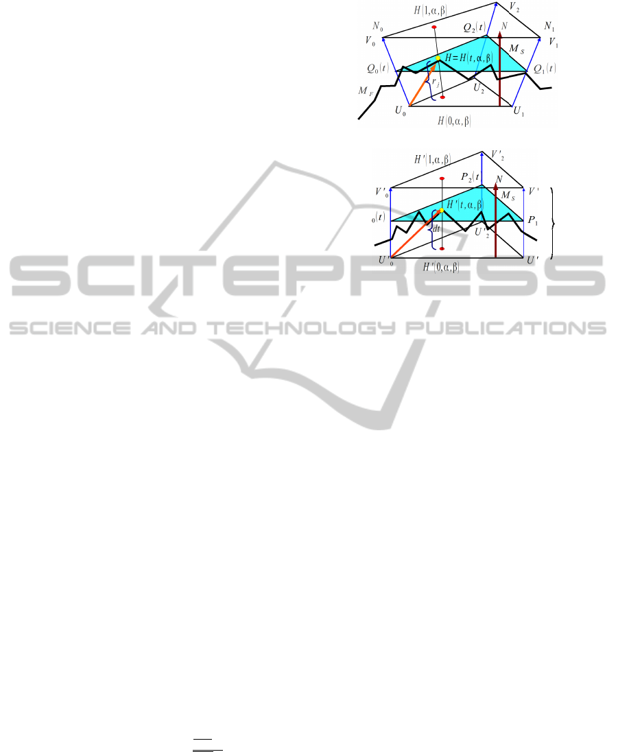
The volumes H and H’ (the triangular wedge built
around triangle i of the simplified mesh, and its corre-
sponding orthogonal prism) map to each other para-
metrically in normalized barycentric coordinates (α,
β, γ) throughout trilinear interpolation.
Both meshes are loaded and placed congruently
(same size, origin and orientation). A prism is grown
at each face of the M
s
mesh alongside vertices’ nor-
mals (both up and down), as shown on Figure 1. This
will triple the number of vertices of the mesh, and
multiply by 9 the number of triangular faces. Each
face f of the mesh M
s
is traversed (order is irrelevant),
placing a camera a constant distance d from the center
of face f and orthogonal to it.
Values α and β (and γ = 1− α− β) are barycentric
coordinates, and H(t, α,β) = H
′
(t, α,β) the height value
corresponding to these texture coordinates. At this
point, coordinates are transformed to the local space
of wedge i, following the transformation T
i
to an or-
thogonal prism onto the corresponding triangle at the
atlas (see Figure 1) and the heightfield channel at that
point is sampled.
The distance d is pre-computed by a binary search
of the minimum wedge height value ensuring that
the whole surface geometry will be enclosed by all
wedges. Prism corners V
j
and U
j
are computed from
vertex Q
j
, displaced a perpendicular distance ±d/2
along the face normal, equivalent to some value r
j
along each vertex normal N
j
, as shown by Equation 1.
Q
j
(t) = U
j
+t(V
j
−U
j
), Q
j
(t) = U
j
+t(r
j
N
j
)
P
j
(t) = U
′
j
+t(V
′
j
−U
′
j
), P
j
(t) = U
′
j
+t(dN)
j = 0,1,2,. .. t =
U
0
H·N
U
0
V
0
·N
(1)
Vertices V
k
from the M
F
mesh that fall within the face
prism are tagged and warped onto the corresponding
orthogonal wedge by means of an (invertible) trans-
formation T
i
, a trilinear interpolation to obtain the
transformed vertices V
′
k
.
N
2
(a) Mesh prism before warp
1
1
M '
F
d
P
1
t
2
(b) Mesh prism after warp
Figure 1: Heightfield Displacement Computation: Trans-
formation T
i
warps all vertices V
k
’s in M
F
that are within the
face’s prism to the orthogonal prism
To obtain the relative base height ofV
k
, we project
the distance vector from this vertex to one of the ver-
tices of the simpler mesh M
s
against the face normal.
The magnitude t of the projected vector will be the
relative height. Original vertex coordinates are recov-
ered by applying T
−1
i
to the transformed vertex V
′
k
.
H(t, α,β) = αQ
1
(t) + βQ
2
(t) + γQ
0
(t)
H
′
(t, α,β) = αP
1
(t) + βP
2
(t) + γP
0
(t)
(2)
H(t, α, β) = α[Q
1
(t) − Q
0
(t)] + β[Q
2
(t) − Q
0
(t)] + Q
0
(t)
H
′
(t, α, β) = α[P
1
(t) − P
0
(t)] + β[P
2
(t) − P
0
(t)] + P
0
(t)
1 = α+ β + γ, with α,β,γ,t ∈ R[0..1]
To obtain the barycentric coordinates used to sample
the texture, the prism is orthogonalized, warping the
volume enclosed along the vertex normals (H) into a
regular triangular prism with vertex normals parallel
to the face normal (H
′
), as shown on Equation 2 Given
t
∗
, having γ = 1 − α − β, and knowing triangle ver-
tices {Q
′
k
s, P
′
k
s}, we have all the information needed to
compute the T
i
mapping. Notice that Q
j
(0.5) = P
j
(0.5),
since they are vertices from the same base triangle k
of mesh M
s
. Having both spaces H and H
′
parametri-
cally equivalent, instead of solving a 16 by 15 linear
system to find the 15 elements on a local warp matrix,
we solve for each vertex a much simpler 2× 2 linear
system to obtain the < α, β > pairs. As long as trian-
gles are non-degenerate (a feature of good decimation
algorithms), it is straightforward to derive T
−1
i
, the in-
verse transformation from tangent to object space.
GeneralizedHapticReliefAtlasforRenderingSurfaceDetail
193
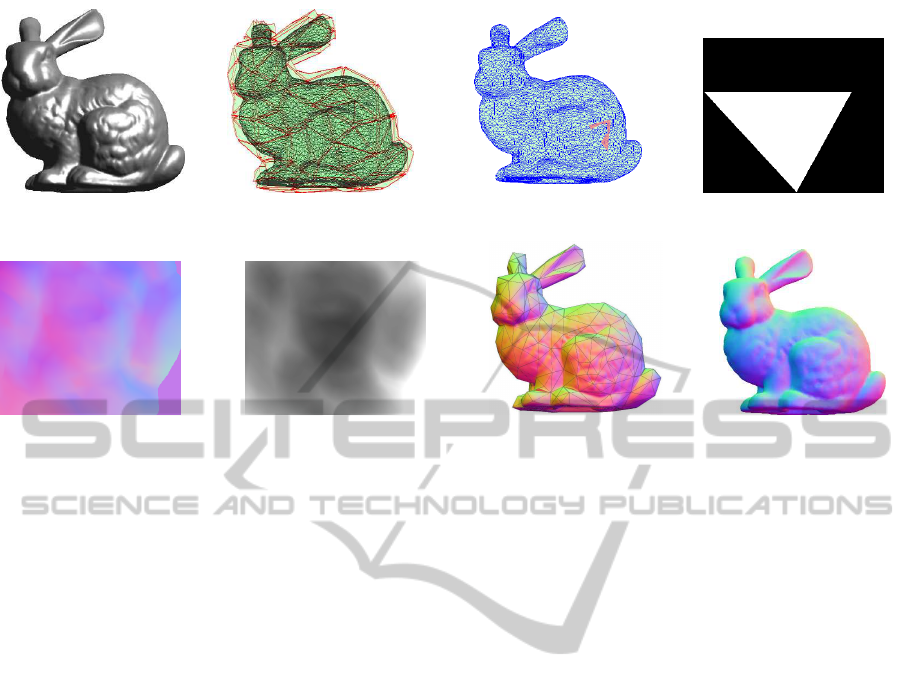
(a) Original mesh M
f
(b) Prisms of simple mesh M
s
capturing relief of M
f
(c) Current prism atop M
f
(d) Current face (white) mask
(e) Rendered face normal map (f) Rendered face z-buffer (g) Tangent-space atlas atop
decimated mesh M
s
(no relief
represented)
(h) Tangent relief sampled at
fragment shader for decimated
mesh M
s
)
Figure 2: The complete sequence for tangent atlas construction and image-based relief generation.
It follows that G
0
and G
1
continuity are guaran-
teed across edges, since a point on the shared edge of
two adjacent faces of M
s
will be mapped to the same
height at both sides, and its normal will be the same.
Therefore, when traversing the surface of mesh M
s
, all
transitions across edges will be undetectable, and will
be perceived as non-abrupt continuous surface.
3.2 Generating the Relief Atlas in GPU
The resulting submesh of M
f
(Figure 2(a)) is then
rendered to an off-screen framebuffer using a ver-
tex+fragment GPU shader, as seen on Figure 2(h).
Each face of M
s
(Figure 2(b)) gets focused by a
camera placed just outside of the top lid of the prism,
and the same transformation is applied to mesh M
f
.
An orthonormal projection samples homogeneously
the relief volume without precision loss.
Mesh M
f
is then rendered from that point of view,
with an overlap border of two pixels, to avoid ren-
dering artifacts at the edge borders. All vertices be-
longing to M
f
within the space of constructed prism
(slightly grown to actually including some neighbour-
ing outer vertices and faces to avoid special cases
when triangles of the low and high resolution mesh
coincide at edges or verices) are warped to the orthog-
onal prism, as previously explained in Figure 1.
The current face area as a stencil (Figure 2(c)),
to simultaneously cut the renderings of mesh M
f
to
the depth buffer in the range between the two lids of
the prism, (Figure 2(f)), and the corresponding nor-
mal map (Figure 2(e)). The procedure is repeated for
each triangle of the M
s
mesh, collecting all HyRMA
pairs in the atlas one by one. To save memory and disk
space, the texture triangles are sorted by edge size
and stored alternately facing up and down. The corre-
sponding uv coordinates are also stored in a separate
text file. An example of textured triangles is shown
in Figure 3, with the normalmap RGB channel (Fig-
ure 3(a)) and the relief map α channel (Figure 3(b)).
The processing part first phase of the texture gen-
eration takes enough time (several seconds) so it is not
suitable for realtime generation (yet). However, after
a tangent atlas has been generated (it only needs to be
done once), rendering relief is quite fast.
4 TANGENT-SPACE RELIEF
ATLAS RENDERING
The procedure for rendering higher visual detail is
straightforward: Load the lower resolution mesh M
s
,
the tangent-space texture atlas, the corresponding uv
mapping coordinates, then use a vertex shader to map
vertices to its correspondent uv mapping, prism and
texture, and the modified parallax occlusion fragment
shader takes the brunt of the work for relief rendering.
A run of the shading procedure (without relief
heights, to show the underlying mesh) is shown on
Figure 2(g), and the generated image with relief depth
and normals calculated by the parallax occlusion
shader is shown on Figure 2(h). Quality of volume de-
GRAPP2013-InternationalConferenceonComputerGraphicsTheoryandApplications
194
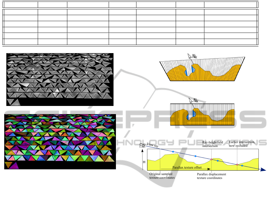
Table 1: Test Hi and Lo meshes.
HiRes mesh Triangles LoRes mesh Triangles RGBα Texture Avg. FPS Avg. POM iterations
sphere4 5,120 sphere1 80 1024×1536 645 10
sphere8 1,310,720 sphere2 320 2048×932 223 5
bunny 144,046 bunny512 512 4096×1407 226 10
bunny 144,046 bunny8192 8192 4096×2048 171 5
armadillo 32768 armadillo1024 8192 4096×8192 155 5
armadillo 345,944 armadillo16384 16384 8192×16384 92 3
(a) Depth atlas (Stanford Bunny, 256 faces)
(b) Normalmap atlas (Stanford Bunny, 256 faces)
Figure 3: Tangent atlas for the Stanford Bunny, stored by
edge length with alternating orientation.
tail depends on texture size for each rendered triangle
in tangent space, and a maximum size of 256x256 or
512x512 per triangle of mesh M
s
is quite adequate for
quick and accurate relief rendering. The creation of a
tangent atlas texture is a lossy transformation. As seen
in Figure 4, obtaining the atlas will eliminate some
concave holes, since they (Figure 4(a) will be trans-
formed orthogonally and lose subsurface empty vol-
ume. When reconstructed, holes’ walls will be along
the surface interpolated normals (Figure 4(b)), hav-
ing minor effects in lighting and shadow generation,
depending on the decimation level.
Modified Parallax Occlusion Mapping Shader
The fragment shader has some modifications from the
standard POM shader, to account for correct sampling
of the atlas, as shown in Figure 4(c):
1. In the vertex shader pass, the base triangle is iden-
tified (all 1+8 triangles from the same prism share
the same tag), and variables are set up for the
fragment shader pass, warping the entry and exit
points of the view ray crossing the prism.
2. A linear search loop samples several points back
to front, from the view ray’s exit point up to the
(a) Before Warp: concave region (in blue) won’t be included in
the tangent atlas
(b) Reversing the transformation renders a modified geometry
with smoothed holes
(c) A View Ray in orthogonal prism space samples the relief repeatedly in
tangent space (blue circles). Two Ray intersections (in red) are shown; right-
most one is occluded
Figure 4: Tangent atlas warp.
prism’s entry point. The sampling rate is adjusted
according to the angle between the view ray and
the geometric normal of the face, higher for near
horizontal rays, and close to 1 in near vertical
rays. If the ray’s height is lower than the sam-
pled relief height, search for the boundary along
the ray (towards the camera), and find the point in
which the ray hits the heightfield surface.
3. Obtain the parallax displacement, displace the
pixel in tangent space, and then unwarp to obtain
the real displacement.
4. Optionally, provide a loop for lights and shadows.
The procedure for shadow pixels is similar, but
using light rays for the calculation.
5 RESULTS
The testing equipment for the procedure is an Intel(R)
Core(TM) Quad CPU Q9550 (2.83GHz, 64 bit) with
a NVIDIA GeForce 9800GT (1 GB) graphics card,
GeneralizedHapticReliefAtlasforRenderingSurfaceDetail
195

having OpenGL v.3.3 – GLSL v.330. Except in the
sphere models, most triangles are dissimilar, and may
be represented by small pixel chunks in the map. Tex-
ture files have a maximum horizontal width of 8192
pixels, but are limitless in length. Texture size for
each individual triangle is 256× 256 or 512× 512.
Several models where chosen: Spheres at vary-
ing resolutions (an icosehedron being the ”simpler”
mesh); the Stanford Bunny mesh (144,046 triangles,
72,027 vertices); the Armadillo mesh (345,944 faces,
172,974 vertices). Table 1 shows several resolutions
of the meshes of each model.
There is not much difference rendering meshes
with one million triangles and one of five thousand.
A high number of triangles is offset by the reduced
individual size of each texture and its parallax ren-
dering. Only those triangles that are near silhouette’s
edges or belonging to sharp features need more iter-
ation, since front-facing triangles will have very little
parallax displacement, and the fragment shader does
not spend much time iterating. This means that for
each object model there is an optimal combination of
high and low resolution meshes that allows rendering
all geometric detail with the best performance.
Overall, using the same haptic image-based map
for visually rendering meshes guarantees enough pro-
cessing time for the high frequency sampling of colli-
sion detections needed for accurate force perception.
6 CONCLUSIONS
An approach using a haptic image-based relief atlas
in warped tangent space, computed out of a low res-
olution mesh and a highly detailed is shown. The ap-
proach is geared for adequate visual surface represen-
tation when interacting with haptic detail. Savings in
processing time may be dedicated to better calculate
collisions against geometry, necessary for good detail
perception in meshes with high polygon counts.
The procedure allows reducing this to a prepro-
cessing step involving a low resolution mesh to com-
pute a low distortion warped relief texture in tangent
space, and a texture sampling approach in a fragment
shader that produces good detail at interactive rates,
unwarping the texture and producing apparente geo-
metric relief using a modified POM shader.
Instead of parallax mapping, geometric displace-
ment mapping may be used, to sample the texture and
unwarp the resulting points to generate more points
using a geometryshader. The method can be extended
to multiresolution tangent atlases, generating separate
mipmap relief textures at varying resolutions, allow-
ing for more or less detail when zooming at the scene.
ACKNOWLEDGEMENTS
This work has been co-financed by project TIN2010-
20590-C02-01 from Spain’s Ministry of Education.
REFERENCES
Baboud, L. and D´ecoret, X. (2006). Rendering geometry
with relief textures. In Graphics Interface ’06, Que-
bec, Canada.
Carr, N. A. and Hart, J. C. (2002). Meshed atlases for real-
time procedural solid texturing. ACM Trans. Graph.,
21(2):106–131.
Dachsbacher, C. and Tatarchuk, N. (2007). Prism Parallax
Occlusion Mapping with Accurate Silhouette Genera-
tion. In ACM Symposium on Interactive 3D Graphics
and Games (I3D 2007).
Gain, J. and Bechmann, D. (2008). A survey of spatial
deformation from a user-centered perspective. ACM
Trans. Graph., 27(4):107:1–107:21.
Gonz´alez, F. and Patow, G. (2009). Continuity map-
ping for multi-chart textures. ACM Trans. Graph.,
28(5):109:1–109:8.
Hirche, J., Ehlert, A., Guthe, S., and Doggett, M. (2004).
Hardware accelerated per-pixel displacement map-
ping. In Proceedings of Graphics Interface 2004, GI
’04, pages 153–158.
Hoppe, H. (1999). New Quadric Metric for Simplifying
Meshes with Appearance Attributes. In IEEE Visual-
ization 1999 Conference, pages 59–66.
L´evy, B., Petitjean, S., Ray, N., and Maillot, J. (2002). Least
squares conformal maps for automatic texture atlas
generation. ACM Trans. Graph., 21(3):362–371.
Policarpo, F. and Oliveira., M. M. (2007). Relaxed cone
stepping for relief mapping. In Nguyen, H., editor,
GPU Gems 3, chapter 18, pages 409–428. Addison-
Wesley Professional.
Policarpo, F., Oliveira, M. M., and Comba, J. L. D. (2005).
Real-time relief mapping on arbitrary polygonal sur-
faces. In SI3D ’05: Proceedings of the 2005 sym-
posium on Interactive 3D graphics and games, pages
155–162, New York, NY, USA. ACM Press.
Rusinkiewicz, S. (2012). Trimesh2 C++ mesh library.
http://gfx.cs.princeton.edu/proj/trimesh2/. PIXL –
Princeton ImageX Labs, New Jersey, NJ, USA.
Szirmay-Kalos, L. and Umenhoffer, T. (2008). Displace-
ment Mapping on the GPU – State of the Art. COM-
PUTER GRAPHICS forum, 27(6):1567–1592.
Tarini, M., Pietroni, N., Cignoni, P., Panozzo, D., and
Puppo, E. (2010). Practical quad mesh simplification.
Computer Graphics Forum, 29(2):407–418.
Tatarchuk, N. (2006). Dynamic parallax occlusion mapping
with approximate soft shadows. In SI3D06, pages 63–
69.
Theoktisto, V., Fair´en, M., and Navazo, I. (2010). A hy-
brid rugosity mesostructure (HRM) for rendering fine
haptic detail. CLEI Electronic Journal (CLEIej) ISSN
0717-5000, 13(3).
Timonen, V. and JanWesterholm (2010). Scalable Height
Field Self-Shadowing. COMPUTER GRAPHICS fo-
rum, EuroGraphics 2010 issue, 29(2):723–731.
Visual Computing Lab, ISTI–CNR, Pisa, Italy (2012).
MeshLab. http://meshlab.sourceforge.net/.
GRAPP2013-InternationalConferenceonComputerGraphicsTheoryandApplications
196
