
FEASIBILITY STUDY ON
MICROWAVE POWER TRANSMISSION TO A ZIGBEE DEVICE
FOR WIRELESS SENSOR NETWORK
Tomohiko Mitani, Takuya Ichihara, Nozomu Suzuki, and Naoki Shinohara
Research Institute for Sustainable Humanosphere, Kyoto University, Gokasho, Uji, Kyoto, Japany
mitani@rish.kyoto-u.ac.jp
Keywords: Wireless power transmission, ZigBee, Wireless sensor network
Abstract: The objective of the present study is to drive or charge a ZigBee device wirelessly by microwave power
transmission. Wireless sensor network is expected to monitor several systems in order to control various
infrastructures, such as electric power consumption, actively. However, power supply for sensor terminals is
a critical problem to realize a fruitful wireless sensor network system. Primary batteries needs to be changed
soon or later, wired power supply confines their installation location, and natural energy utilization like
solar cells limits their regular operation. We therefore suggest wireless power supply for the sensor
terminals by microwave power transmission. We adopt a ZigBee device as a wireless sensor terminal
because of its low power consumption. We experimentally investigated electromagnetic compatibility
between ZigBee and microwave power transmission, and found that there were some frequencies and power
levels of microwave power transmission not to interrupt ZigBee. We also developed a microwave power
receiving system which consists of a receiving antenna, a rectification circuit, a dc-dc converter, and a
power storage circuit or a secondary battery. Finally we succeeded establishment of ZigBee network while
driving a ZigBee device without batteries by microwave power transmission. Through the experiments, we
found out intermittent microwave power transmission was preferable to CW microwave power transmission
with respect to electromagnetic compatibility and rf-dc efficiency.
1 INTRODUCTION
Wireless sensor network is becoming an attractive
application for monitoring systems such as energy
conservation systems of buildings and houses, traffic
management systems, environment monitoring
systems etc. A vast number of wireless sensor
terminals are scattered over a wide area, and send
and receive monitoring information through ad hoc
network. The collected information will be utilized
to control various infrastructures, such as electric
power consumption, actively.
One of the critical issues of the wireless sensor
network is the way to supply electric power for
sensor terminals. Primary batteris need to be
changed soon or later even though power
consumption of the sensor terminals is quite small.
That will make the running cost of the wireless
sensor network expensive. Wired power supply can
provide stable operation of the sensor terminals;
whereas it confines their installation location and
burdens the wireless sensor network with wired cost.
Natural energy utilization like solar cells with a
charging system will drive the sensor terminal
permanently; however their installation location and
regular operation are limited because the natural
energy is quite unstable.
We therefore suggest wireless power supply to
the sensor terminals by microwave power
transmission (MPT), in order to realize a fruitful
wireless sensor network. MPT is able to provide a
stable power for the sensor terminals, transmits
power even for a long distance, supplies the power
for multiple terminals simultaneously, and even
drives the terminals without batteries. By utilizing
MPT for the wireless sensor network, we can
provide new applications of the wireless sensor
network as well as the envisioned ones. A great
potential application is a wireless sensor network
system for disaster relief, as shown in Figure 1.
Wireless sensor terminals located in any places
normally sleep but work in emergency situations by
receiving the power from vehicles or helicopters via
29
Mitani T., Ichihara T., Suzuki N. and Shinohara N.
FEASIBILITY STUDY ON MICROWAVE POWER TRANSMISSION TO A ZIGBEE DEVICE FOR WIRELESS SENSOR NETWORK.
DOI: 10.5220/0005413500290034
In Proceedings of the First International Conference on Telecommunications and Remote Sensing (ICTRS 2012), pages 29-34
ISBN: 978-989-8565-28-0
Copyright
c
2012 by SCITEPRESS – Science and Technology Publications, Lda. All rights reserved
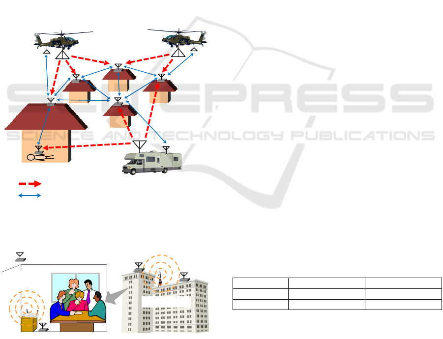
long-range MPT. The activated terminals can collect
and send disaster information via short-range
wireless communication. Another application is
“energy harvesting” from radio communication
(Kawahara, 2009). The energy harvesting system by
receiving VHF or UHF energy from TV towers were
reported in 2009 (Sample, 2009). Mobile
communication systems and wireless local area
network systems, as shown in Figure 2, will be
potential candidates as energy harvesting source in
microwave band.
The objective of the present study is to drive or
charge a wireless sensor terminal by MPT. We adopt
a ZigBee device as wireless sensor terminal because
of its low power consumption. In this paper we
describe our current status of MPT to a ZigBee
device, including our previous studies on
development of a microwave power receiving circuit
(Suzuki, 2010), and feasibility of intermittent MPT
(Ichihara, 2012).
Microwavepowertransmission
Short‐rangewirelesscommunication
Figure 1: A conceptual image of a wireless sensor network
system for disaster relief.
WLAN
routeretc.
・・・SensorTerminal
Celltower etc.
Figure 2: A conceptual image of energy harvesting from
radio communications in microwave band.
2 OUTLINE OF MPT SYSTEM TO
ZIGBEE DEVICE
2.1 Zigbee Device
ZigBee is one of the radio communication standards
and appropriate for the sensor network for the
following reasons: its power consumption is lower
than wireless LAN and Bluetooth, its production
cost is low, and its network capacity is large. Its low
power consumption is beneficial for a MPT system
from the viewpoint of electromagnetic compatibility
between MPT and ZigBee.
In the present study, we are using
IEEE802.15.4/ZigBee Evaluation and Development
Kit TWE-EK-001 produced by Tokyo Cosmos
Electric Company (TOCOS) as ZigBee devices.
ZigBee network consists of the coordinator, a router
and an end device. The coordinator is only one in a
ZigBee network system and it coordinates the
network. The router has the function of relaying data
from other routers and end devices as well as
monitoring. The end device only has the function of
monitoring and data sending. Therefore the power
consumption of the end device is lower than the
coordinator and the router. Table 1 shows measured
average power consumptions of a router and an end
device of this kit. The power consumption of the
router is stable whether or not it joins in the
network; whereas the power consumption of the end
device is quite small when it joins in the network.
We have studied on MPT to an end device in the
present paper.
In our configuration, the router and the end
device sent data for nearly 2 milliseconds every 1.14
seconds. The coordinator decided to drop them from
its network if it had not received data from them for
15 seconds. When it had dropped out of the network,
the device was requested to join in the network again.
Table 1: Measured average power consumption of ZigBee
devices.
Device type Joining Not joining
Router 57.4 mW 57.1 mW
End device 9.46 mW 61.8 mW
2.2 Microwave Power Receiving
Circuit
Figure 3 shows a schematic of a microwave power
receiving circuit. The microwave power receiving
First International Conference on Telecommunications and Remote Sensing
30
circuit consists of a receiving antenna, a rf-dc
rectifier, a power storage circuit, and a dc-dc
converter. The combination of the receiving antenna
and the rf-dc rectifier is called “rectenna”. The
power storage circuit can be omitted when the
transmitted microwave power is large enough to
drive a ZigBee device directly. The dc-dc converter
converts the rectenna output voltage to a regulated
voltage for a stable ZigBee device operation.
We adopt 2.4 GHz ISM-band, which is the same
frequency band as ZigBee, as MPT frequency, from
the viewpoint of efficient frequency usage. In this
study, continuous or intermittent microwave without
modulation transmits power to the receiving circuit.
Microwave
power
Rf‐dc
rectifier
Receivingantenna
Powerstorage
circuit
Dc‐dc
converter
ZigBee
(enddevice)
ZigBee
communication
From/to
coordinator
orrouter
From
transmitting
antenna
Figure 3: A schematic of microwave power receiving
circuit.
3 EXPERIMENTAL STUDY ON
COMPATIBITITY BETWEEN
MPT AND ZIGBEE
We firstly conducted experimental measurements of
electromagnetic compatibility between MPT and
ZigBee, in order to investigate how MPT affected
ZigBee. Also the measurements contributed to fix
the frequency and maximum transmitting power of
MPT in our study.
We defined and evaluated two indices on MPT
power density: communicable power density (CPD)
and joinable power density (JPD). CPD is the
threshold of MPT power density which does not
affect ZigBee. A ZigBee device can communicate
with the other one under the CPD when it has
already joined in the network. JPD is the threshold
of MPT power density under which a ZigBee device
can join in the network. The CPD is generally larger
than the JPD.
3.1 Measurement Setup
Figure 4 shows the experimental configuration. The
ZigBee frequency was set to 2.46 GHz (22 ch), and
the network had just two devices of the coordinator
and an end device. First, the coordinator, which was
put behind the transmitting horn antenna, established
communication with the end device. Then, the end
device was irradiated with non-modulated
microwave as alternative to MPT. We measured
CPD with increasing the non-modulated microwave
power until the communication was disabled. After
that, we measured JPD with reducing the non-
modulated microwave power until the coordinator
established communication with the end device
again.
We investigated two types of non-modulated
microwave irradiation: CW microwave irradiation
and intermittent microwave irradiation. During the
intermittent microwave irradiation, the non-
modulated microwave turned on and off under the
conditions of a pulse frequency and a duty ratio.
78.0cm
575cm
ZigBee
enddevice
Directional
coupler
Power
meter
43dB
Amplifier
(20W max)
ZigBee
coordinator
Signal
Generator
Figure 4: Experimental configuration of electromagnetic
compatibility between MPT and ZigBee.
3.2 Measurement Results
3.2.1 CW microwave irradiation
We conducted CW microwave irradiation to a
ZigBee end device, with changing the frequency
from 2.4 GHz to 2.5 GHz (20 MHz step). We
measured the maxima of the CPD and JPD at all the
frequency points.
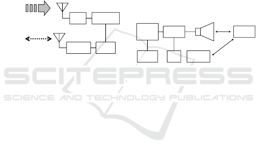
Experimental results of the CPD and JPD are
shown in Figure 5. At all the frequency points, the
CPDs were lower than 1 mW/cm
2
– the maximum
power density determined by International
Commission on Non-Ionizing Radiation Protection
(ICNIRP, 1998). Around the ZigBee frequency, the
power density of 5 pW/cm
2
even interrupted ZigBee.
From these results, CW MPT is quite difficult to be
compatible with ZigBee, in order to supply enough
power wirelessly for a ZigBee device. Although we
have not checked yet, CW MPT at another
frequency band except 2.4 GHz band might be
compatible with ZigBee.
Feasibility Study Onmicrowave Power Transmission to a Zigbee Devicefor Wireless Sensor Network
31
1.E-9
1.E-8
1.E-7
1.E-6
1.E-5
1.E-4
1.E-3
1.E-2
1.E-1
1.E+0
2.4 2.41 2.42 2.43 2.44 2.45 2.46 2.47 2.48 2.49 2.5
Power density / (mW/cm²)
Frequency / GHz
Maximum of
communicable power
density (CPD)
Maximum of joinable
power density (JPD)
Figure 5: Measurement results of the CPD and JPD when
the ZigBee end device was irradiated with CW microwave.
3.2.1 Intermittent microwave irradiation
Under the same condition as shown in Figure 4, we
conducted intermittent microwave irradiation to a
ZigBee end device. We fixed the intermittent
microwave frequency of 2.46 GHz, at which we
obtained the lowest maximum of the CPD and JPD
in the CW microwave irradiation case. The end
device was irradiated with intermittent microwave,
within the pulse frequency range from 1 Hz to 200
Hz and the duty ratios of 0.1, 0.5 and 0.9.
From experimental results, 1.91 mW/cm
2
of the
peak power density with any duty ratios allowed the
end device to participate in the network and
communicate with the coordinator. This means the
CPD and JPD of the intermittent microwave is more
than 10
8
times larger than those of CW microwave,
when the MPT frequency is the same as the ZigBee
frequency.
We also measured error rates of ZigBee during
the intermittent microwave irradiation. Experimental
results under the peak power density of 1.91
mW/cm
2
are shown in Figure 6. Since we fixed the
peak power density in the measurements, the
average power density was dependent on the duty
ratio: 0.191 mW/cm
2
, 0.955 mW/cm
2
and 1.72
mW/cm
2
at the duty ratios of 0.1, 0.5 and 0.9,
respectively. The experimental results show that the
ZigBee end device could communicate with the
coordinator almost perfectly at the duty ratio of 0.1;
whereas it seemed difficult for the ZigBee end
device to send data stably at the duty ratio of 0.9.
In the measurements, interference would occur
stochastically because we made the period of
intermittent microwave irradiation irrelevant to that
of ZigBee. Therefore, it is important to build a
scheduling rule between intermittent MPT and
ZigBee for a robust wireless sensor network with
MPT.
0
20
40
60
80
100
1 10 100
Error rate / %
Pulse frequency / Hz
0.1 0.5 0.9
Duty ratio
Figure 6: Measurement results of error rates when a
ZigBee end device was irradiated with intermittent
microwave under the peak power density of 1.91 mW/cm
2
.
4 DEVELOPMENT OF A
RECEIVING CIRCUIT
4.1 Rectenna
Rectenna consists of a receiving antenna and a rf-dc
rectifier. As with the experiments in Section 2, we
focused on the MPT frequency of 2.46 GHz.
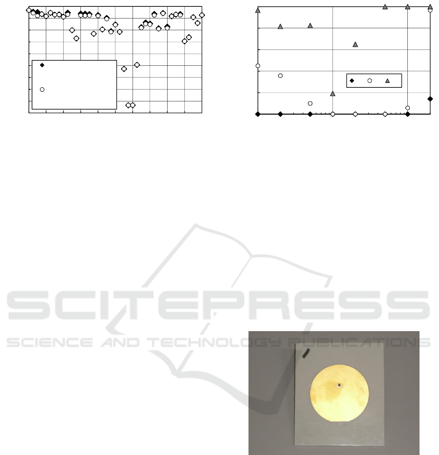
Circular patch antenna was adopted as receiving
antenna. Figure 7 shows a photograph of the circular
patch antenna. The measured antenna gain was 6.5
dBi.
Figure 7: Photograph of the circular patch antenna.
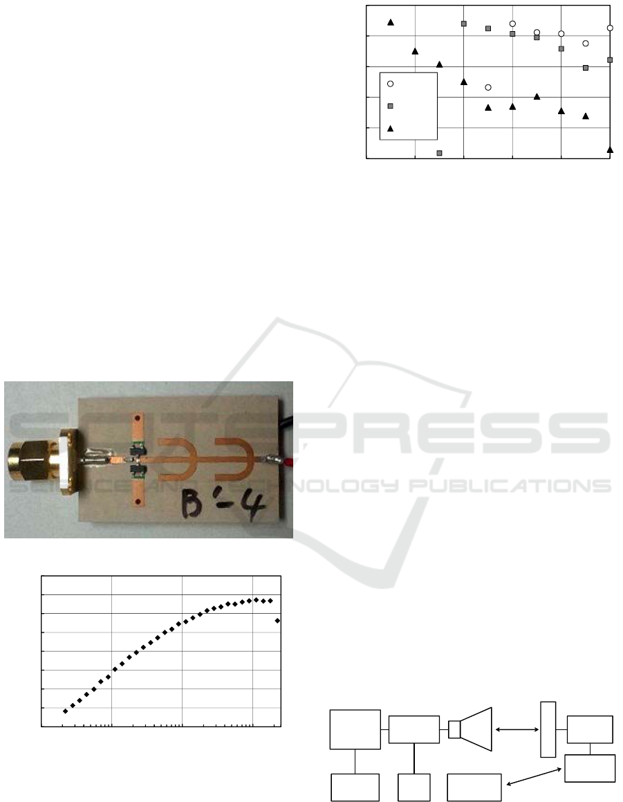
We developed a single-shunt type rf-dc rectifier,
whose photograph is shown in Figure 8. We adopted
Schottky barrier diode (Avago HSMS-2860) as
rectifier diode. Measurement results of rf-dc
conversion efficiency are shown in Figure 9. The
rectifier provided the maximum rf-dc conversion
efficiency of 65 % at 2.46 GHz when the output load
was 138.1 ohms, in the CW microwave case (Suzuki,
2010). The rf-dc conversion efficiency started to be
dropped at an input power of 180 mW. This drop in
conversion efficiency is related to the breakdown
voltage of the diode.
First International Conference on Telecommunications and Remote Sensing
32
We also investigated rf-dc conversion efficiency
when the intermittent microwave was input to the
rectifier. The duty ratio of the intermittent
microwave was changed from 1 (CW) to 0.1, the
pulse frequency was 1 kHz, and the average input
power was 16 mW, 65 mW and 101 mW. Since we
fixed the average input power, the peak input power
was dependent on the duty ratio. The peak input
power was equal to the average input power at the
duty ratio of 1; whereas it became 10 times larger
than the average input power at the duty ratio of 0.1.
Figure 10 shows measurement results of rf-dc
conversion efficiency in the intermittent microwave
case. Of great interest is that the rf-dc conversion
efficiency depended on the peak input power. Even
if the average power is small, one can obtain the
maximum rf-dc conversion efficiency by adjusting
the duty ratio of intermittent microwave. The rf-dc
conversion efficiency dropped down at low duty
ratios when the average input power was 65 mW and
101 mW, because the peak input power became over
the input power of 180 mW, where the rf-dc
conversion efficiency started to be dropped.
Figure 8: Photograph of the rf-dc rectifier (Suzuki, 2010).
0
10
20
30
40
50
60
70
80
0.1 1 10 100
Rf-dc conversion efficiency / %
Input power / mW
Figure 9: Rf-dc conversion efficiency of the rectifier in the
CW microwave case.
56
58
60
62
64
66
0 0.2 0.4 0.6 0.8 1
Rf-dc conversion efficiency / %
Duty ratio
101 mW
65 mW
16 mW
Figure 10: Rf-dc conversion efficiency of the rectifier in
the intermittent microwave case.
4.2 Dc-dc converter
The rectenna output voltage became over 4 V at the
input microwave power of 180 mW from the
measurement results; whereas the ZigBee input
voltage should be in the range from 2.7 V to 3.6 V.
We therefore adopted a step-down dc-dc converter
(Texas Instruments TPS62120) as dc-dc converter.
This dc-dc converter provided an efficiency of over
90 % in an output voltage range around 3 V.
5 INTERMITTENT MPT
DEMONSTRATION TO
ZIGBEE DEVICE
We conducted demonstration experiments of power
supply to a ZigBee end device by intermittent MPT.
A demonstration configuration and a photograph of
the demonstration are shown in Figure 11 and Figure
12, respectively. The MPT frequency was 2.46 GHz,
and the pulse frequency was changed from 1 Hz to
50 Hz. Three rectennas were connected in series.
The ZigBee end device had no batteries, that is, it
was driven only by intermittent MPT. In this
demonstration, we fixed a peak power density of 2.4
mW/cm
2
at the rectenna position.
175.0cm
575cm
ZigBee
enddevice
Directional
coupler
Power
meter
43dB
Amplifier
(20W max)
ZigBee
coordinator
Signal
Generator
3Rectennas
Dc‐dc
converter
Figure 11: Configuration of intermittent MPT
demonstration to a ZigBee end device.
Feasibility Study Onmicrowave Power Transmission to a Zigbee Devicefor Wireless Sensor Network
33

Figure 12: Photograph of intermittent MPT demonstration
to a ZigBee end device.
From the demonstration experiments, the end
device was driven by intermittent MPT at any pulse
frequency when the duty ratio of the intermittent
MPT was above 0.4. We therefore succeeded
battery-less operation of the ZigBee device by MPT.
Moreover, when the pulse frequency was 10 Hz, the
end device could communicate with the coordinator
with no error, while its power was being supplied by
MPT.
6 CONCLUSIONS
We succeeded MPT to a ZigBee device which was
driven without batteries. Intermittent MPT was
preferable to CW MPT because of the following
reasons: ZigBee was better compatible with MPT,
and higher peak power of MPT was allowed. The
latter factor contributed to higher rf-dc conversion
efficiency of the rectifier even at the low average
power. Moreover we confirmed that the ZigBee end
device worked and communicated correctly with the
coordinator while its power was being supplied by
intermittent MPT.
As future works, we will study on scheduling
management between MPT and ZigBee. Although
we succeeded intermittent MPT demonstration to a
ZigBee device as a feasibility study, scheduling
management will be essential for realizing a fruitful
wireless sensor network. Also we will have to study
how to transmit microwave power to multiple
ZigBee devices in a wide area.
ACKNOWLEDGEMENTS
A part of the present study is supported by The
Japan Prize Foundation.
REFERENCES
Ichihara, T., Mitani, T., Shinohara, N., 2012. Study on
Intermittent Microwave Power Transmission to a
ZigBee Device. In Proc. of 2012 IEEE MTT-S
International Workshop Series on Innovative Wireless
Power Transmission: Technologies, Systems, and
Applications (IMWS-IWPT 2012), pp.209-212.
International Commission on Non-Ionizing Radiation
Protection (ICNIRP), 1998. Guidelines for Limiting
Exposure to Time-varying Electric, Magnetic, and
Electromagnetic Fields (up to 300 GHz). Health
Physics, 74 (4), pp.494-522.
Kawahara, Y., Lakafosis, V., Sawakami, Y., Nishimoto,
H., Asami, T., 2009. Desing Issues for Energy
Harvesting Enabled Wireless Sensing Systems. In
Proc. of Asia-Pacific Microwave Conference 2009
(APMC 2009), pp.2248-2251.
Sample, A., Smith, J. R., 2009. Experimental Results with
two Wireless Power Transfer Systems. In Proc. of
IEEE Radio and Wireless Symposium 2009
(RWS2009), pp.16-18.
Suzuki, N., Mitani, T., Shinohara, N., 2009. Study and
Development of a Microwave Power Receiving
Circuit for ZigBee Device. In Proc. of Asia-Pacific
Microwave Conference 2010 (APMC 2010), pp.45-48.
First International Conference on Telecommunications and Remote Sensing
34
