
Two-arm Robot Teleoperation using a Multi-touch Tangible User
Interface
Andreas Angerer, Andreas Bareth, Alwin Hoffmann, Andreas Schierl, Michael Vistein
and Wolfgang Reif
Institute for Software and Systems Engineering, University of Augsburg, D-86135 Augsburg, Germany
Keywords:
Software Architecture, Teleoperation.
Abstract:
Teleoperation of robots can be interesting in various scenarios: operation in hazardous environments, medical
surgery in the presence of radiation or, in general, remote control of robots in (partially) unknown environ-
ments. Crucial to teleoperation systems is an intuitive interface for the remote operator to ensure straightfor-
ward and precise control of the operated system. Advanced hardware devices and powerful software frame-
works allow for quick development of such interfaces. We present a case study implementing a novel two-arm
robot teleoperation interface using multi-touch and tangible user interface concepts. The focus lies on the
implementation of this system, using an object oriented robot programming framework and the Microsoft
Surface as a user interface platform.
1 INTRODUCTION
Recent progress in sensor hardware, sensor informa-
tion processing and cognititive capabilities led to a
significant increase in the autonomy of (mobile) robot
systems. Robots can autonomously fetch objects (Jain
and Kemp, 2010), open doors (Meeussen et al., 2010),
and even cook pancakes (Beetz et al., 2011). While
this progress leads to less involvement of human op-
erators in some areas, there are other cases where hu-
man intervention is desirable or even indispensable –
e.g. in rescue robotics, where certain decisions should
rather be taken by a human than relying on a machine.
In these areas, teleoperation systems that support hu-
man operators in efficiently controlling robot systems
remotely play an important role.
A variety of teleoperation systems has already
been developed, mostly targeted at controlling the
navigation of mobile robots. In (Skrzypczyliski,
1997), a graphical interface has been developed to
achieve telepresence for an operator navigating a mo-
bile robot through indoor environments. A similar
concept is employed in (Zalud, 2006) with a special
focus on data fusion of various sensors to augment
the picture taken by the robot’s main camera. In both
projects, visual feedback by cameras as well as 3D
visualization of the scenery play an important role.
Besides different concepts for presenting data to
the operator, new user interface concepts like multi-
touch have also been applied to robot teleoperation.
Micire et al. (Micire et al., 2011) presents a system
based on the Microsoft Surface for remote operation
of a mobile robot through an intuitive multi-touch in-
terface. In (Seifried et al., 2009), a multi-touch table-
top device is used for controlling several home de-
vices, including a vacuum cleaner robot. In those sys-
tems, the intuitiveness of (multi-)touch user interfaces
is used for easing the remote operation.
In this work, we present a multi-modal, tangible
user interface for teleoperation of a two-arm robot
system. We developed this system mainly as a case
study to evaluate the usefulness of an object oriented
robot application framework called the Robotics API
(cf. (Angerer et al., 2010)); the experiences made
will be illustrated in this work. Besides that, this
system could serve as an intuitive way to operate
a mobile two-arm robot which is currently planned
to be built at our institute. On the hardware side,
two KUKA Light Weight Robot (LWR) arms were
used. These 7-axis robot arms achieve industry-grade
movement precision, and integrated torque sensors
and corresponding control algorithms (Bischoff et al.,
2010) open up interesting possibilities e.g. for force-
controlled manipulation. Those sensors can, however,
also provide valuable feedback in a teleoperation sce-
nario, as will be illustrated later. For realizing the tele-
operation user interface, we employed the Microsoft
Surface platform
1
and the corresponding SDK.
1
http://www.microsoft.com/surface/
327
Angerer A., Bareth A., Hoffmann A., Schierl A., Vistein M. and Reif W..
Two-arm Robot Teleoperation using a Multi-touch Tangible User Interface.
DOI: 10.5220/0004046503270332
In Proceedings of the 9th International Conference on Informatics in Control, Automation and Robotics (ICINCO-2012), pages 327-332
ISBN: 978-989-8565-22-8
Copyright
c
2012 SCITEPRESS (Science and Technology Publications, Lda.)
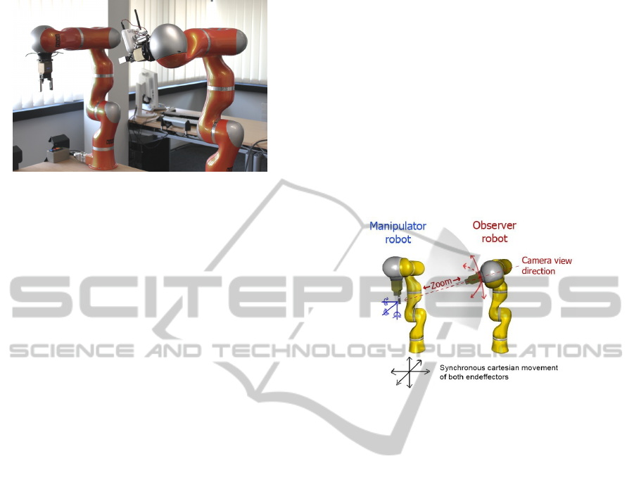
Figure 1: Light Weight Robot setup.
The paper is structured as follows: In Sect. 2, the
concepts and user interface of the developed teleoper-
ation application are explained. Sect. 3 explains the
implementation challenges and how those could be
adressed using the Robotics API. The following Sect.
4 presents some experimental results. Finally, Sect. 5
concludes the work and gives an outlook.
2 A TANGIBLE USER
INTERFACE FOR
TELEOPERATION
This work is focused on a rather simple test sce-
nario: A tele-operator should be able to pick work-
pieces from some location and put those workpieces
to any target location. Though the core steps in this
task are quite simple, it may involve preliminary steps
like deciding a gripping strategy (see (Siciliano and
Khatib, 2008), pp. 671) or even moving other ob-
jects that block access to the workpiece to be trans-
ported. A human operator can infer most of those
necessary steps quickly from just observing the scene
(or the camera picture, respectively), in contrast to
complex cognition steps in an automated robotic sys-
tem. The tele-operator should be able to perform pick
and place tasks with intuitive support by the teleop-
eration system. Similar to previous work in this area
(see Sect. 1), visual perception of the scene is con-
sidered very important and should be realized here by
a single camera, mounted next to the gripper of one
of the robot arms. Fig. 1 shows the laboratory setup
of both Light Weight Robots. The observer robot
is equipped with a simple network camera (Intellinet
NSC15-WG), which utilizes Wireless LAN for trans-
mitting the video stream to the application.
The teleoperation system supports two distinct
modes of operation: In the direct control mode , the
robot arm with the camera mounted on it performs
the gripping task. In this mode, the movement of
the camera (and thus the scene perceived by it) cor-
responds directly to the arm movement commanded
by the user. It can be considered a “first person” per-
spective. In the observer mode, the robot arm with the
camera mounted takes an observer position, while the
second robot arm, the manipulator robot, performs the
actual task (cf. Fig. 2). The observer robot automat-
ically follows movements of the manipulating robot.
The operator can rotate the camera robot around the
observed point of interest. Additionally, by moving
the observer robot closer to or further away from the
point of interest, a zooming functionality can be real-
ized. Thus, the scene can be observed flexibly.
Figure 2: Observer mode.
As mentioned before, the user interface of the pro-
posed teleoperation system is based on the Microsoft
Surface platform. This platform consists of a table-
shaped, touch-sensitive 30-inch display and a cor-
responding Software Development Kit. In contrast
to many touch-sensitive devices nowadays, the Mi-
crosoft Surface utilizes optical recognition of fingers
or other objects that touch it. Therefore, arbitrary
shapes can be recognized, as well as special graphi-
cal tags.
The application designed for teleoperation on the
Microsoft Surface offers a user interface consisting of
four main parts as shown in Fig. 3. The camera pic-
ture (1) is shown in the top center part of the user
interface area, where it is in the center of the opera-
tor’s field of view. Below the camera view, a 3D view
(2) of the robots is located. The view can be rotated
and zoomed in order to get a good overview of the
robots’ poses. It listens to data supplied by the robots’
joint position sensors and updates the pose visualiza-
tion accordingly. The perspective can be rotated by
swiping over the view with one finger, and zoomed
by swiping two fingers in opposite directions. Ad-
ditionally, pre-defined perspectives on the scene can
be activated by pressing one of the buttons for Left,
Top, Right, Front or Back perspective (cf. Fig. 4).
The view also displays the Cartesian forces measured
at the robots’ endeffectors, which are visualized as ar-
ICINCO2012-9thInternationalConferenceonInformaticsinControl,AutomationandRobotics
328
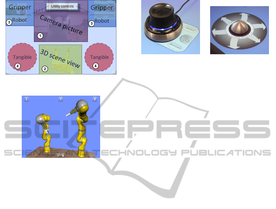
Figure 3: Overview of the tangible teleoperation user inter-
face.
Figure 4: 3D visualization of robot poses.
rows pointing in the direction of the measured force.
The length of the arrows indicates the magnitude of
the force. This proved to be valuable feedback for the
operator to judge the current state of the system.
For controlling the robot arms during teleopera-
tion, a combination of physical objects and virtual
user interface elements is used. The motion control of
the manipulator robot is realized using the 3D mouse
SpaceNavigator by 3Dconnexion. This 6-DOF mouse
can be used to intuitively control cartesian movement
and rotation of the robot endeffector. The SpaceNav-
igator is at the same time used as a tangible user in-
terface element: When it is placed somewhere on the
teleoperation UI (4), a Surface tag sticked to its bot-
tom is recognized by the application. The user inter-
face control shown in Fig. 5 is displayed and at the
same time, movement of the manipulator robot arm is
enabled. From then on, the SpaceNavigator controls
the robot movement. The displayed control provides
additional selectable options, in particular switching
from direct mode to observer mode and vice versa.
In observer mode, the observing robot arm can be
rotated around the manipulator robot’s endeffector in
two dimensions (up/down and left/right). Addition-
ally, the user can zoom into and out of the perspec-
tive by moving the observer robot closer to or further
away from the manipulator robot. This three degrees
of freedom are controlled by a second tangible inter-
face element, which is a simple hemispherical object
with a Surface tag attached to it. Upon contact to the
Figure 5: Visualization of
the manipulator robot con-
troller.
Figure 6: Visualization of
the observer robot con-
troller.
Surface, the UI control shown in Fig. 6 is displayed.
Moving the tangible element outside the center of the
visualization rotates the observer robot, while rotating
the tangible element when it is inside the center zone
controls the zoom level by moving the observer robot
closer to or away from the manipulator robot’s tool
The UI elements depicted as (3) in Fig. 3 provide
some utility controls for the robots (e.g. moving to
safe positions) and grippers.
3 IMPLEMENTATION
CHALLENGES AND
CONCEPTS
The teleoperation application as described in the pre-
vious section posts the following requirements to the
underlying robot control framework:
1. Reading Sensor Data: information about the cur-
rent robot positions and the measurements of the
torque sensors have to be provided.
2. Cartesian Velocity Control: for the proposed 6-
DOF mouse and tangible input devices, control of
the Cartesian velocity of the robot arms is most
adequate. Thus, means of specifying Cartesian
velocity set points are required.
3. Movement Synchronization: in observer mode, the
movement of the observer robot needs to be syn-
chronized to the manipulator robot’s movement.
Note that the observer robot may itself be moving
with a certain velocity relative to the manipulator
robot (i.e. when changing the observer perspec-
tive), so both requirements need to be combinable.
The application was implemented using the
Robotics API (cf. (Angerer et al., 2010)), an object-
oriented robot control framework developed in the
research project SoftRobot. It is a modular frame-
work for developing real-time critical robotic applica-
tions. It supports the development of complex multi-
robot applications, including real-time robot coopera-
Two-armRobotTeleoperationusingaMulti-touchTangibleUserInterface
329
Robot Control Core
Realtime Primitives Interface
Implementation
Application Application
Robotics API
Robot Hardware
Real-Time Robot Control
Application Programming
Non Real-Time Environment
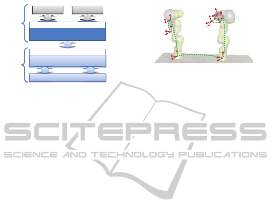
Figure 7: Robot control architecture used for implementa-
tion of the teleoperation system.
tion and sensor-controlled manipulation. The frame-
work’s architecture consists of two main parts (cf.
Fig. 7), the Robotics Application Programming In-
terface (Robotics API), and a Robotics Control Core
(RCC) which provides the Realtime Primitives In-
terface (RPI, see (Vistein et al., 2010)). The core
idea behind this architecture is a splitting of concerns
when developing robotic applications: the application
workflow can be developed using the object-oriented
Robotics API which provides a set of concepts to
support the developer, like classes encapsulating ma-
nipulator or tool functionality, classes for modeling
frames and physical objects and classes for access-
ing and processing sensor data. Actuator operations,
reactions to defined events and actuator synchroniza-
tion can be defined by means of Robotics API con-
cepts. Subsequently, they are automatically mapped
to an RPI dataflow command specification and trans-
ferred to the Robotics Control Core, which ensures
real-time critical execution of those requests. In that
way, real-time robot control is encapsulated and sep-
arated from high-level application workflow.
The Robotics API provides means of reading a va-
riety of sensor data which matches the first require-
ment of the teleoperation application. Reading sensor
data is performed by registering SensorListener ob-
jects to instances of the Sensor class. The measure-
ment values delivered by a respective driver module
in the RCC are then automatically propagated to the
registered listeners.
Controllable Devices like robot arms are modeled
by specialized versions of the Robotics API class Ac-
tuator. Actuators have the ability to execute certain
Actions, like joint or Cartesian motions (for robots)
or gripper commands (for grippers). Instances of the
class Robot, which is a subclass of Actuator, also sup-
port the execution of Actions that accept velocity set
points as input during their execution. One such Ac-
tion is called CartesianJogging. Its implementation
employs an online planner and ensures that the spec-
Base frame
Flange frame
Camera frame
Gripper
frame
Gripper
frame
Flange frame
Base frame
Figure 8: Relevant frames for CartesianJogging in teleoper-
ation. Dotted lines indicate connections between frames.
ified cartesian translational and rotational velocities
are established by the robot’s endeffector in a contin-
uous way. The CartesianJogging action is used in the
teleoperation application to achieve the desired carte-
sian velocity control by mapping deflections of the
6-DOF mouse and movement of the observer robot
tangible control to target velocity values.
Considering movement synchronisation, the
Robotics API provides some built-in support by its
world model. Cartesian coordinate systems, modeled
by the Frame class, may be moving relative to other
frames (like a robot’s endeffector frame relative
to its flange frame) and Action implementations
are provided information about the current state
(position, velocity) of moving frames and have to
respect this. In particular, CartesianJogging requires
two Frames as parameters: The reference frame
defines the base frame relative to which the jogged
frame should be moving with the specified velocity.
If the reference frame is itself moving, the Action’s
implementation ensures that the motion is followed
in addition to the specified jogging velocity. This
feature is useful for the application’s observer mode:
here again, a CartesianJogging Action can be used
with an appropriate choice of the reference frame.
Fig. 8 shows all frames that are relevant in the
teleoperation application.
One problem remains considering the zooming
functionality of the observer robot: During zoom-
ing, the center of rotation of the observer robot’s
CartesianJogging should stay in the position of the
manipulator robot’s endeffector. This was not the
case with the existing implementation of Cartesian-
Jogging, which used the jogged frame’s position as
rotation center (i.e. the observer robot’s camera frame
in this case). To solve this problem in a generic way,
we extended the definition of the CartesianJogging
Action by introducing a third frame, called the pivot
frame. This frame’s position is used as point at which
to apply rotational jogging velocities. By choosing
the manipulator robot’s endeffector frame as pivot
frame for the observer robot’s jogging Action, the be-
havior is as desired.
ICINCO2012-9thInternationalConferenceonInformaticsinControl,AutomationandRobotics
330
4 EXPERIMENTAL RESULTS
The developed teleoperation system was successfully
tested using two Lightweight Robot arms mounted on
a table. For a first validation of its effectiveness, we
put up a test scenario consisting of several objects ran-
domly placed in a box. The task was to pick a certain
object from the box. Such challenges arise in practi-
cal teleoperation scenarios as well, like handling con-
taminated material in nuclear power plants, or search-
ing for survivors in destroyed buildings. In most
cases, multiple actions (moving away blocking ob-
jects) were necessary to get access to the desired ob-
ject. The operators (students, postgraduates and pro-
fessors with technical background) had no eye con-
tact to the robots, they had to stick to the information
provided by the teleoperation system. After a short
learning phase, they could all complete the task suc-
cessfully. The observer mode was the preferred mode
of operation, as it proved to be more flexible due to the
ability to inspect the scene from various perspectives.
Although the task of moving objects seems quite sim-
ple, the experiments showed that quite some visual
and haptic information is required to correctly judge
the geometric properties and relations of the involved
objects.
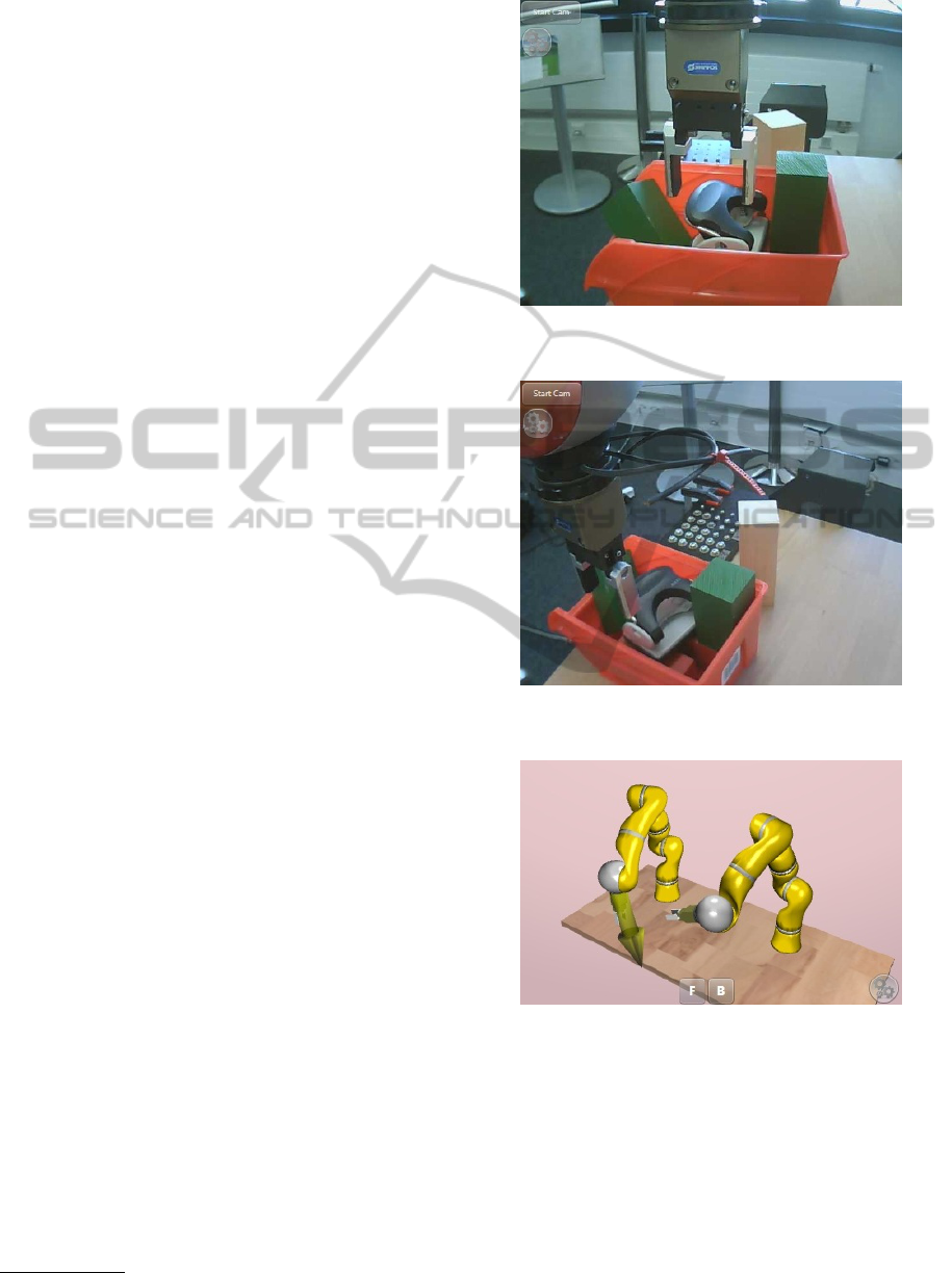
Fig. 9 shows a scene from the experiments. Fig. 10
shows the same scene viewed from a different an-
gle by adjusting the observer robot. This example
shows how the ability to change perspective helps in
judging the situation: From just observing the first,
central perspective on the scene, the operator cannot
recognize whether the robot’s gripper is positioned
above the hole-puncher that should be fetched from
the box. By rotating the perspective, the situation be-
comes clearer. The visualization of the contact force
as shown in Fig. 11 offers the operator an additional
perceptional dimension and can help to resolve visual
ambiguities. A video of the application is available
2
.
5 CONCLUSIONS
In this work, we presented an application for teleop-
eration of a two-arm robot system. The realization
employs multi-touch and tangible user interface con-
cepts and is realized on the Microsoft Surface plat-
form. The implementation of the teleoperation system
concentrated mainly on the user interface design and
the general application logic. Interfacing the robot
arms showed to be straightforward and simple due to
the rich framework support provided by the Robotics
2
http://video.isse.de/teleop
Figure 9: Manipulated object viewed from a central per-
spective.
Figure 10: Manipulated object viewed from a side perspec-
tive.
Figure 11: Force visualization during contact to the object.
API for controlling the arms as well as monitoring the
various sensors. The CartesianJogging action proved
to be a powerful tool for creating a flexible, velocity-
based robot control interface. However, we learned
that its initial definition using two frames did not
cover all practical cases of expected behavior, so we
had to extend it by introducing an additional frame.
Currently, we are working on some extensions to
the current implementation to make the system more
robust. In the current state, reaching a robot’s joint
Two-armRobotTeleoperationusingaMulti-touchTangibleUserInterface
331

limits leads to termination of the jogging action and
requires it to be restarted. Similar problems arise
in singular robot poses. First tests with strategies
that limit joint velocities in such situations look very
promising.
In the future, we will continue to create case stud-
ies like this one, as we see them as an excellent option
for evaluating the current state of a software frame-
work. Beyond that, the developed teleoperation sys-
tem could be a valuable tool for controlling e.g. a
planned mobile two-arm manipulator.
ACKNOWLEDGEMENTS
This work presents results of the research project
SoftRobot which was funded by the European Union
and the Bavarian government within the High-
Tech-Offensive Bayern. The project was carried
out together with KUKA Laboratories GmbH and
MRK-Systeme GmbH and was kindly supported by
VDI/VDE-IT.
REFERENCES
Angerer, A., Hoffmann, A., Schierl, A., Vistein, M., and
Reif, W. (2010). The Robotics API: An object-
oriented framework for modeling industrial robotics
applications. In Proc. 2010 IEEE/RSJ Intl. Conf. on
Intelligent Robots and Systems (IROS 2010), Taipeh,
Taiwan, pages 4036–4041. IEEE.
Beetz, M., Klank, U., Kresse, I., Maldonado, A.,
M
¨
osenlechner, L., Pangercic, D., R
¨
uhr, T., and
Tenorth, M. (2011). Robotic roommates making pan-
cakes. In 11th IEEE-RAS International Conference on
Humanoid Robots, Bled, Slovenia.
Bischoff, R., Kurth, J., Schreiber, G., Koeppe, R., Albu-
Sch
¨
affer, A., Beyer, A., Eiberger, O., Haddadin, S.,
Stemmer, A., Grunwald, G., and Hirzinger, G. (2010).
The KUKA-DLR lightweight robot arm - a new ref-
erence platform for robotics research and manufactur-
ing. In Proc. IFR Int. Symposium on Robotics (ISR
2010).
Jain, A. and Kemp, C. (2010). El-e: an assistive mobile
manipulator that autonomously fetches objects from
flat surfaces. Autonomous Robots, 28:45–64.
Meeussen, W., Wise, M., Glaser, S., Chitta, S., McGann, C.,
Mihelich, P., Marder-Eppstein, E., Muja, M., Eruhi-
mov, V., Foote, T., Hsu, J., Rusu, R. B., Marthi, B.,
Bradski, G., Konolige, K., Gerkey, B., and Berger, E.
(2010). Autonomous door opening and plugging in
with a personal robot. In Int. Conference on Robotics
and Automation.
Micire, M., Desai, M., Drury, J. L., McCann, E., Norton, A.,
Tsui, K. M., and Yanco, H. A. (2011). Design and val-
idation of two-handed multi-touch tabletop controllers
for robot teleoperation. In Proc. 15th Int. Conf. on
Intelligent User Interfaces, IUI ’11, pages 145–154,
New York, NY, USA. ACM.
Seifried, T., Haller, M., Scott, S. D., Perteneder, F., Rendl,
C., Sakamoto, D., and Inami, M. (2009). CRISTAL: a
collaborative home media and device controller based
on a multi-touch display. In Proc. ACM Int. Conf.
on Interactive Tabletops and Surfaces, ITS ’09, pages
33–40, New York, NY, USA. ACM.
Siciliano, B. and Khatib, O., editors (2008). Springer Hand-
book of Robotics. Springer, Berlin, Heidelberg.
Skrzypczyliski, P. (1997). Supervision and teleoperation
system for an autonomous mobile robot. In Proc.
1997 IEEE/RSJ Int. Conf. on Intelligent Robots and
Systems, volume 2, pages 1177 –1181 vol.2.
Vistein, M., Angerer, A., Hoffmann, A., Schierl, A., and
Reif, W. (2010). Interfacing industrial robots using
realtime primitives. In Proc. 2010 IEEE Intl. Conf. on
Automation and Logistics (ICAL 2010), Hong Kong,
China, pages 468–473. IEEE.
Zalud, L. (2006). ARGOS - system for heterogeneous mo-
bile robot teleoperation. In Proc. 2006 IEEE/RSJ Int.
Conf. on Intelligent Robots and Systems, pages 211
–216.
ICINCO2012-9thInternationalConferenceonInformaticsinControl,AutomationandRobotics
332
