
A PRACTICAL IMPLEMENTATION OF A FUNCTIONAL
DOMAIN WITHIN A CLOUD
Jonathan Eccles
1
and George Loizou
1,2
1
Department of Computer Science and Information Systems, Birkbeck, University of London,
London WC1E 7HX, U.K.
2
Department of Computer Science and Engineering, European University Cyprus,
1516 Nicosia, Cyprus
Keywords: Cloud Architecture, Profiles, Policy Management, Virtualization, Abstraction Classes, Service Control.
Abstract: This summary describes a specific aspect of the work that has been done to virtualize the IT server estate of
a company with a modern business architecture of about 3-400 servers. This results in a practical server
environment with the same architecture and servers and integrated networking in an abstracted form by
using sets of HP c7000 chassis units. This has been done by applying hypervisor-based Virtualization
technologies to clusters implemented across constituent blades between sets of chassis units. This working
system is enhanced by enabling specific HP c7000 operational capabilities together with separate
virtualization technologies, which are consolidated in a single coherent design model that is enabled as a
virtualized system implemented within one to three HP c7000 chassis units on a single site. Furthermore,
this system is enhanced by enabling virtual L3 Ethernet via specific HP c7000 chassis operational
capabilities which are consolidated in a single coherent design mode. The system is now enhanced to
operate on a multiple site basis and also to use physical as well as virtual systems (e.g. servers, appliances,
applications, networks, storage) in the same functional domain.
1 INTRODUCTION
There are many projects now underway which
involve producing virtualized environments to
support large-scale systems. Some of these are
created as the result of physical-to-virtual
transformation programs where, in the first instance,
virtual servers may replace the equivalent physical
servers. In many cases, this may not involve any
improvement in design other than the consolidation
of server processes inherent in the virtual model.
However, the virtualization paradigm may yield
many improvements in systems architecture and
design at many levels (Daniels, 2009), some of
which are discussed in an upcoming paper (Eccles
and Loizou, in preparation_a).
It is often the case that the system designer
requires a method in order to be able to model and
simulate part of the target system using the
infrastructure intended to support it. In this case the
target system constitutes a virtualized environment
and the infrastructure that complements it is also
made up of virtualized components. These
virtualized components are derived from the
orchestration policy which is in turn part of the
modelling system as shown in
Figure 2. The target
area for the Functional Domain (FD) is given as the
specific layer in the model that is derived via the
orchestration system whose function is to take not
just the Virtual Machine (VM) object references, but
also the Virtual Appliance (VA) object references
and construct the equivalent virtual objects in the
designated FD, subject to the policy of that specific
FD. Additionally, the target system is fabricated as
part of the overall virtualized environment and
essentially can be said to be an FD (Eccles and
Loizou, 2011). This FD is separated from the main
parent virtualized environment by a construct which
we have called a Functional Domain Nexus Interface
(FDNI). (See Figure 1, where NAS RDP, SAN and
VDI stand for Network Accessed Storage, Remote
Desktop Protocol, Storage Area Network and Virtual
Desktop Interface, respectively). The FDNI provides
a secure point of entry to the designated FD such
that neither TCP/IP-based traffic nor files may
traverse the construct in either direction except by
using a specific transit process. Thus the FD is a
secure area within the Virtualized Environment, or
13
Eccles J. and Loizou G..
A PRACTICAL IMPLEMENTATION OF A FUNCTIONAL DOMAIN WITHIN A CLOUD.
DOI: 10.5220/0003904400130026
In Proceedings of the 2nd International Conference on Cloud Computing and Services Science (CLOSER-2012), pages 13-26
ISBN: 978-989-8565-05-1
Copyright
c
2012 SCITEPRESS (Science and Technology Publications, Lda.)
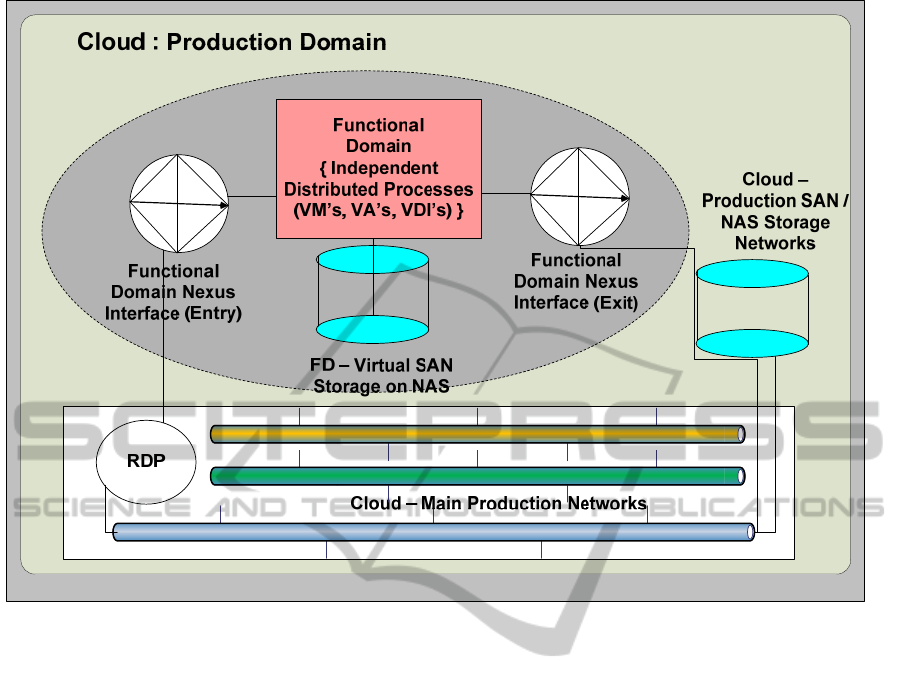
Figure 1: The basic overview of the FD concept within the Cloud.
within the cloud as a whole. This paper describes
how the FDNI and the FD are hosted within a totally
virtualized environment created by using one or
more HP chassis units and a set of blades with X86
hypervisors (VMware ESXi v4.1 (VMware, 2006)).
This concept has been referred to as ‘superhosting’,
since in essence it consists of the hosting of a
virtualized distributed system by a totally virtualized
environment. Distributed systems may be
implemented within this environment and tested
according to requirements. Alternatively, this
method of virtualised systems engineering can be
regarded as a method by which specific areas, within
a dynamic cloud structure, can be defined to exist
within certain policy constraints pertinent to the
specific FD.
This paper introduces the FDNI and will
illustrate the practical development of the associated
FD based on the use of a chassis, blades, and the
chassis-based On-Board Administrator / VC system
together with sets of hypervisors to host sets of VMs
in conjunction with Virtual Ethernets. The detailed
construction of the FDNI in conjunction with its role
in integrated FDs is a key part of another upcoming
paper (Eccles and Loizou, in preparation_b).
One of the key additional areas of practical
development that is shown in this paper is how to
enable the practical extension of the FD across more
than one site within a Wide-Area Network (WAN).
The corollary of this is that the Functional Design
object gains the properties of being able to integrate
with physical servers or appliances as well as virtual
ones. This leads to highly flexible designs for FDs
within the business environment context of the cloud.
This paper also discusses how the classes and
inter-connectivity of the constituent VMs is based on
modelling structures (Carman, 2001) and paradigms
for the virtualized cloud that are the focus of an
upcoming paper (Eccles and Loizou, in
preparation_a). The latter modelling structures are
initially based on those used for distributed systems
and are modified so as to produce networks of VMs,
VAs and Virtual Storage in the context of an FD.
Therefore this paper presents a new way of
formulating a solution to the problem of producing a
practical model for a (virtualized) subsystem of a
distributed application. This can be used in the
assessment of the performance and the behaviour of
the latter by direct access and measurement of the
relative performance and capabilities of the sub-
CLOSER2012-2ndInternationalConferenceonCloudComputingandServicesScience
14
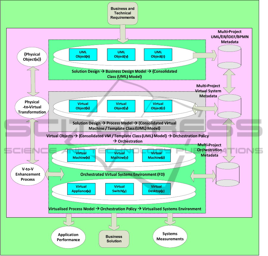
Figure 2: Derivation of the practical Virtualized Environment from the Process Model of the VMs created from the
Physical-to-Virtual Process Model.
components with reference to the system as a whole
(Menasce and Almeisida, 2004).
2 PRELIMINARIES
2.1 Current Paradigms
The initial purpose of this work was to meet the
challenge of delivering the same functional solution
at the application level to the business problems
faced by a customer, but at a much lower level of
delivery cost (say 30%), and also at a much lower
level of cost with respect to future expansion and
implementation. This requires that the solution be at
least an order of magnitude more flexible and able to
add more value. In order to achieve this, it is
required that the new system be modelled (Niculescu
and Moldovan, 2005) at every level, and also ideally
virtualized at every level in a fully networked
abstracted environment. (The requirement to be
virtualized is not essential as is shown in the WAN-
based testing FD (
Figure 10)).
This solution becomes important not only
because of the implicit reduction in costs but also
because the mapping of the business perspective to
APRACTICALIMPLEMENTATIONOFAFUNCTIONALDOMAINWITHINACLOUD
15

the technological areas used in the abstracted
environment allows for transparent integration of
systems to improve performance, and also to extend
the lifetime of most classes of legacy systems.
Therefore, the solution extends the natural lifetime
of a legacy system, as it becomes virtualized and
therefore no longer dependent on the functioning of
its hosting hardware. Additionally, it enables the
evolution of proven software programs to become
more powerful by becoming part of larger-scale
integrated systems, which in turn may become a part
of a virtualized enterprise. Over time, this virtualized
environment provides a vehicle to enable service-
based implementations, eventually enabling the
deployment of SOA (Service Oriented Architecture)
in a virtualized environment.
A more immediate purpose of this work was to
enable the delivery of a virtualized FD that mimics
the Production Domain but also has the capability of
independent policy-based control. This must
simulate the business problems faced by the
customer and must enable system testing within an
effective Proof-of-Concept (PoC) virtualized
environment. Within this requirement the capital
cost of the interface to the virtualized FD (PoC)
must equate to zero. This necessitates a solution that
is at least an order of magnitude more flexible and
able to add more value. In order to achieve this, it is
required that the new system be modelled and
virtualized at every level in a fully abstracted
networked environment. The natural extension to
this scenario is how to enable the virtualized FD to
operate in a transparent manner across a WAN. This
requires the production of an effective FD that may
serve as a PoC operating between operational
domains or network sites. Such a system must be
able to include physical as well as virtual servers in
the PoC operational server set.
2.2 Current Approaches
The only current alternative approaches proposed to
creating an FD for use as, for example, a PoC are
those that are recognized as ‘standard’ within the IT
industry, largely on the grounds of security and risk.
These will have the equivalent properties of an
independent virtualized domain that functions on the
business network, but which forms a fully isolated
environment that is secure. They involve the use of
routers, firewalls and the construction of an
independent network at high capital cost and
uncertain capability with respect to meeting the
specific requirement of keeping the same IP
addressing in the isolated FD environment as is kept
in the parent cloud environment, and yet be secure
with respect to IP address separation. In addition, the
equivalent standard physical network would not be
as flexible nor be as cost-effective, especially with
respect to being extended so as to form integrated
FD sets (Caetano et al., 2007).
2.3 Current Status
The FD system is now in full implementation for
PoC and also for VM / virtual system evaluation
performance testing. This PoC facility now forms a
critical part of the new Physical-to-Virtual system
transferral methodology in the stages of final testing
in the authors’ development facility area for the
generation of Virtualized Environments at minimal
cost.
2.4 New Approaches
One of the key attributes of the concept of an FD,
referred to in (Eccles and Loizou, 2011), involves
the M:M relationship to a business system. This
gives the required degree of flexibility necessary to
enable multiple business systems functions (e.g.
services) to relate to multiple degrees of control
structure on a peer-to-peer basis in conjunction with
hierarchies within a cloud. This leads naturally to the
following formalism for the logical representation of
the properties of a generic FD ; namely,
∀ Network_Node(x
i
) ∃ { Functional_Domain(y) | Network_Node(x
i
) ∈ {Functional_Domain(y)}
∧ ((1 ≤ y
≤ Max(Functional_Domain(y)))
∧ (1 ≤ x
i
≤ Max(Network_Node(x
i
))))
∧ ((Network_Node(x
i
) ∈ {Business_System.Node(a
i
)})
∧ (1 ≤ a
i
≤ Max(Business_System.Node(a
i
))))
∧ ((Business_System.Node(a
i
) ∈ {Functional_Domain(y).BusSys(z)})
∧ (1 ≤ z ≤ Max(Functional_Domain(y).BusSys(z)))) }
CLOSER2012-2ndInternationalConferenceonCloudComputingandServicesScience
16
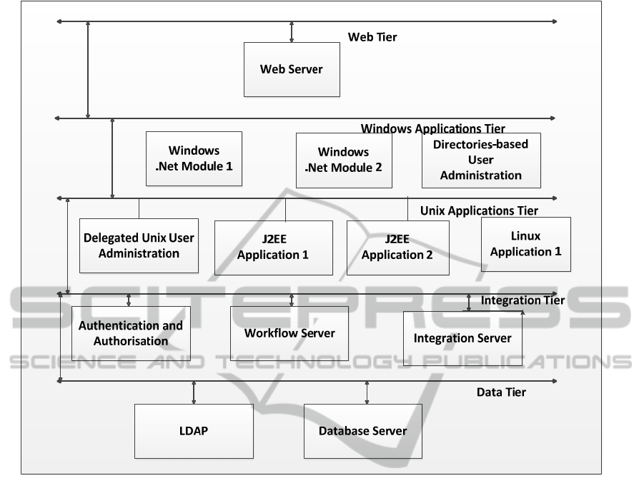
Figure 3: A generic tier-based structure to illustrate the major classes and subclasses of an application that may exist within
a conventional distributed systems environment.
which is in (Eecles and Loizou, 2011).
The concept of the FD, as it is herein presented,
enables the requirement that a node may belong
either to different domains within an operational
session, depending on the set of abstracted processes
being invoked; or alternatively, it may be a member
of more than one domain simultaneously. By
abstracting the concept of the network node within a
cloud, each Network_Node object can be associated
with different subclasses of abstracted cloud classes,
such as those of users, user groups or workstations.
2.5 Server Process Abstraction
There is a great degree of overlap in the structure
and the basic design of a cloud when compared to a
large-scale open enterprise system. There is an ever-
increasing tendency to formulate applications as
distributed systems for a variety of reasons.
Amongst these is the requirement for source code to
become more agile in the sense that it can become
more re-usable. When dealing with conventional
physical systems this essentially means that modules
that are constructed and compiled using such code
(e.g. ActiveX, .NET (Conrad and Dengler, 2000),
CORBA (Mowbry, 1997, Otte, 1996), JMS (Farley,
1998) modules) are copied between different
physical servers. In such cases their degree of
separation within a single project tends to be
governed by their relative degrees of utilization
within that selfsame environment. Thus this pattern
tends to follow the relatively restricted pattern of the
distribution of server class shown in Figure 3.
From this point on it becomes essential to add
value to the process of virtualization, and from there
to the formation of a cloud through the use of
processes that are currently being developed to
consolidate the distribution of VMs in conjunction
with their relative degrees of utilization (Solomon
and Ionescu, 2007). This enhancement of
virtualization is presently being modelled (Eccles
and Loizou, in preparation_a), so as to achieve a
greater level of consolidation of application modules
on the basis of their function with respect to their
APRACTICALIMPLEMENTATIONOFAFUNCTIONALDOMAINWITHINACLOUD
17
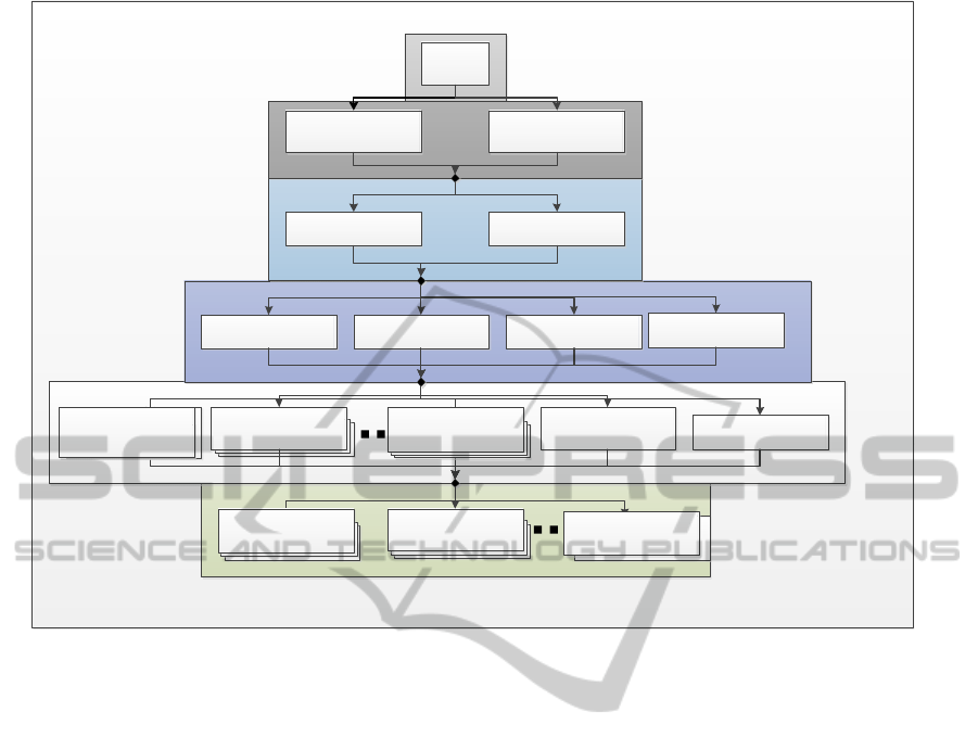
Figure 4: A generic tier-based structure to illustrate the general classes of operating system and systems hosting that may be
compliant with each level of application in a conventional distributed system.
access functions. If the access functions are
distributed and yet owned by separate projects, then
the ownership paradigm must not be a determinant
for which application modules become associated by
threads to the required software modules. This
indicates that many projects can therefore have
temporary ‘ownership’ through the use of associated
threads of one or more virtualized processes.
If this policy is implemented, then the result tends
toward a distributed software environment that is
more in line with that shown in Figure 4. This
illustrates the basis of a distributed environment that
is, whilst ideally virtualized, also shared such that
multiple projects within a business may have access
to the same resource sets (VMs, VAs et al.) that
exist within each level (Loy et al., 2009, Traore et al.,
2003). This concept leads to the formulation of a
generic tier-based structure to illustrate the general
classes of operating system and systems hosting that
may be compliant with each level of application in a
conventional distributed system. The essential
concept to convey at this point is that each instance
of such a structure can be configured to occupy a
single FD, where it may be examined in detail. The
natural extension to this paradigm is that multiple
areas of such shared resources may be deployed
within one or more FDs in the same superhost.
Each such tier contains many VMs, VDIs and
VAs that may be accessed by multiple access
modules from multiple projects. The security level
issues are not addressed in this paper but are the
result of different policies from different FDs
resulting in different software module access
profilers being generated in accordance with
different system requirements.
2.6 Hardware Environment
The Virtualization Environment was developed
using blade technology on an HP c7000 chassis
which has 16 internal device bays. A chassis is able
to host up to 16 half-height blades or up to 8 full-
height blades or any combination of the two
depending on the class of blade. The chassis
operational system was configured using an HP
c7000 Operational Adminstrator (OA) module and
an HP c7000 Virtual Connect (VC) bay module. All
external interface modules (power, network, Host
Bus Adapter (HBA) for Fibre-Channel (FC) storage
access) were implemented in duplicate for seamless
failover. The virtualized environment selected
User
Access
DMZ
Compartment
Client
Compartment
Utility Services
Application
Group 2
Application
Group 2
Standalone
Applications
Physical Virtual
Windows 2000 Windows 2003 Windows 2008
Application
Group 1
Application
Group 1
Application
Group n
Application
Group n
UNIX/Linux
CLOSER2012-2ndInternationalConferenceonCloudComputingandServicesScience
18

involved the use of X86 processor architecture to
implement the VMware ESXi v4.1 hypervisor.This
was done through the use of the HP BL490c blade (2
* 4 core @2.56GHz, 96GB RAM, 2 * 1 Gbps NIC).
The external HBA interface consists of 4 * 4Gbps
FC interfaces to the SAN controller for direct access
to the SAN-based hard drives through an HP
XP24000 storage chassis. The network consisted of
dual 3 * 10Gbps Ethernet from the VC bay (ports
3X, 4X, 5X) implemented as a shared system
connected to the dual Cisco 6509 L3 switches. This
is complemented by a dual link to the NAS storage
drive via a NetApp VFiler which is accessed through
port 6X of the VC bay using IP at 10Gbps. This
hardware setup is duplicated on both sites and is
illustrated in Figure 10. The HP XP24000 SAN is
simulated through the use of a VM in the FD that
accesses the NAS whilst running a software
emulator for the HP XP24000 SAN.
2.7 Proof-of-Concept / Subsystem
Abstraction
The concept of the virtualization of distributed
subsystems has been utilized in order to test
complex distributed applications, some of which
have been produced by Physical-to-Virtual
operations and some through more conventional
UML modelling (Muller, 1997). These VMs are
required to be integrated in a duplicate environment
to that of main production using equivalent software
design but in a situation that was secure and where
the relative performance criteria could be assessed.
This system is now in full implementation for PoC
testing and also for VM Factory testing.
3 DESIGN OF A GENERIC
APPROACH
The initial approach was to undertake an analysis of
the extant physical environment, producing the
required landscape and cost of the basic business
solution. This was followed by a projection based on
the model of future operations with available
compute technology for high level processing,
yielding the initial levels of %CPU utilization based
on physical server hosting. This solution concept
was re-worked using the ‘superhosting’ concepts
described within this paper. A ‘superhost’ is a
computing system capable of running a very large
number, in our case more than 200, COTS
(Commercial Off-the-Shelf)-based subserver
operating systems. These systems are normally
extended applications that are implemented as
distributed systems that have the property of being
able to be interconnected at the level of a routable
protocol (e.g. DCOM, COM+, ODBC, .NET (Corn
and Mayfield, 1998)).
The latter sets of systems also have the
requirement to be interconnected at a routing (L3)
level and are thus able to be implemented within
flexible environments produced by different FDs.
This re-working was followed by process analysis of
the extant physical system as a whole. This is in
order to evaluate the optimum processing capability
of the proposed classes of Target Host server with
reference to the measured utilization of the threads
of the extant physical server processes. From this,
the VM-to-Target Host Server mappings are
computed to evaluate the theoretical Physical-to-
Virtual (P2V) consolidation ratios of the VMs to the
Target Hosts. This can create a number of alternative
mapping scenarios, depending on the sets of VMs
and target classes selected.
The initial approach involved an automated
analysis of the current customer physical
environment, producing the required system and
P2V model and cost of the basic VM-to-target
mapping solution. This was followed by a projection
based on the model of future operations and costings
with available compute technology for high level
processing, yielding the initial levels of %CPU
utilization based on the best projected set of VM-to-
Target mappings. For each functional sub-domain
within the derived host model, this solution concept
as a whole was re-worked using ‘superhosting’ by
employing blades within chassis architectures.
The next step in the Transition Mode of
Operation (TMO) was to create an FD in the HP
c7000 chassis, separated by an FDNI, so as to be
able to create VMs from the current Production area
and test the basic functionality of each generated
VM. This was done by creating sets of Virtual
Ethernets using the VC functions on the HP c7000
chassis. The critical point of the architecture is
where the separation of the independent FD for the
superhost is achieved using the FDNI. The
separation of the Production network into two or
more networks with the same IP subnet domain is
achieved by the FDNI effectively acting as a
network diode, so as to achieve a unidirectional
dataflow between them, where the event of passing
an object through the diode is only able to be
achieved through a deliberate action using a transfer
facility within the FDNI. This degree of separation is
achieved as a consequence of the FDNI
APRACTICALIMPLEMENTATIONOFAFUNCTIONALDOMAINWITHINACLOUD
19

implementing the following criteria: No IP
Forwarding between the two physical NIC’s of the
blade server; Virtual Ethernet Separation via nested
VMs hosting nested firewalls and via Protocol
Separation through a VM hosting a dual-point of
access created to a SAN datavolume, which is
addressed using both the NFS and the CIFS
protocols. This results in no capital cost overhead.
The range of this solution was extended by
evaluating the internetworking of each physical
server with respect to the hosted application’s
dataflow(s), and adding this information to the
model of the current TMO environment. The next
step in the TMO was to create a restricted area in the
HP c7000 chassis in order to be able to create VMs
from the current Production area. This was
complemented by the creation of a TMO ‘proving
area’ to test the basic functionality of each generated
VM. The FD in the proving area enables the
validation and tuning of the VM in conjunction with
final confirmation on the functionality of the VM.
This was followed by the creation of the
Virtualized Ethernets and their inter-connection
using both L2 networking through sets of inter-
connecting VMs. The virtual networks which are
defined within the model are implemented using HP
Virtual Network technology which utilizes OSI
Level 2. We have extended this through the use of
both VAs and VMs. In this case a set of Linux-based
VAs were created to enable OSI Layer 3 routing
between different subnets as well as firewalls to
separate different virtual Ethernet environments,
such as DMZ architectures, within the Virtualized
‘SuperHost’ (cf. Figure 8, Figure 9). This is the most
basic overview utilizing approved modelling
techniques. A full model is multi-layered and too
complex to be included in this short paper. We
utilized the IEEE standard RFC1918 which allowed
the building of controlled networks such that L3
routing was required to enable their inter-
connection.
The initial area of innovation presented here is
the derivation of a full virtualized system from a
complex model. This level of complexity must be
retained as systems management will be integrated
with the full multi-layered model. The main area
presented extends the L2 Virtualized Ethernet to L3
using specific sets of L3 routers implemented as
VAs, which enables the integration of sets of
disparate COTS-based technologies, so that they
may inter-operate transparently in the same HP
c7000 device. This involves using sets of specific
VAs to enhance the functional capabilities of the
Virtualization Management software controlling the
HP Smart Chassis and Blade Solution. The next area
of innovation is to use the described extensions to
enable a VDI layer virtual Ethernet to give a layer of
secure access from the Cisco-based production
network in a transparent manner through an uplink
(Figure 10).
3.1 Functional Domain Nexus Interface
Mk II
Nexus Mk II Zones for the PILOT Environment
Design: the design essentially becomes similar to a
‘Jump Box’ using IEEE RFC1918 networks and
Microsoft Terminal Services technology. A
Microsoft Firewall is active on the Nexus VM. IP
forwarding is NOT permitted on this VM. Shared
FC SAN is still used in the datacentre
implementation allowing the implementation of a
‘Reverse Nexus’. The virtualized equivalents of the
physical environment are consolidated into
Virtualized Ethernets (Vnets) for Vmotion and for
Virtual Business networks that are within a defined
virtual site that hosts the virtualized datacentre. The
VLAN principles for the FD pilot area are that the
VLAN configurations from the Cisco 6509 L3
switch to the HP c7000 chassis are standard for each
production chassis. The term Vnet is used to
describe an HP VC internal chassis network.
Internally, the HP VC module software and
VMWare ESXi hypervisor will be configured to
provide intra-chassis variance. The pilot intra-
chassis variance (Figure 5) will be as per FDNI Mk
II design, where a Vnet connected to production is
present; a Vnet ‘Transit’ NOT connected to
production is present and Vnets ‘Pilot-V-
Production1’ and ‘Pilot-V-Production2’ NOT
connected to ‘Production’ is present. ‘Transit’ Vnet
is a 172 IP; ‘V-Datacentre1’ and ‘V-Datacentre2’
are similar in structure to those in the Production
area, but are segregated by ‘Transit’ and the FDNI
VM from main production.
3.2 Functional Domain: Creation of the
Basic ‘Superhost’
This section illustrates the more detailed
construction of the FD by increasing the complexity,
and thereby the corresponding degree of
functionality, of the superhost. Initially, as shown in
Figure 6, the production network of the cloud is
linked through a VC port (3X, 4X, 5X) of the HP
c7000 chassis to the FDNI entry port via the
production NIC (NIC-1) of the HP BL490c blade
upon which the FDNI / FDNI VM has been installed.
CLOSER2012-2ndInternationalConferenceonCloudComputingandServicesScience
20
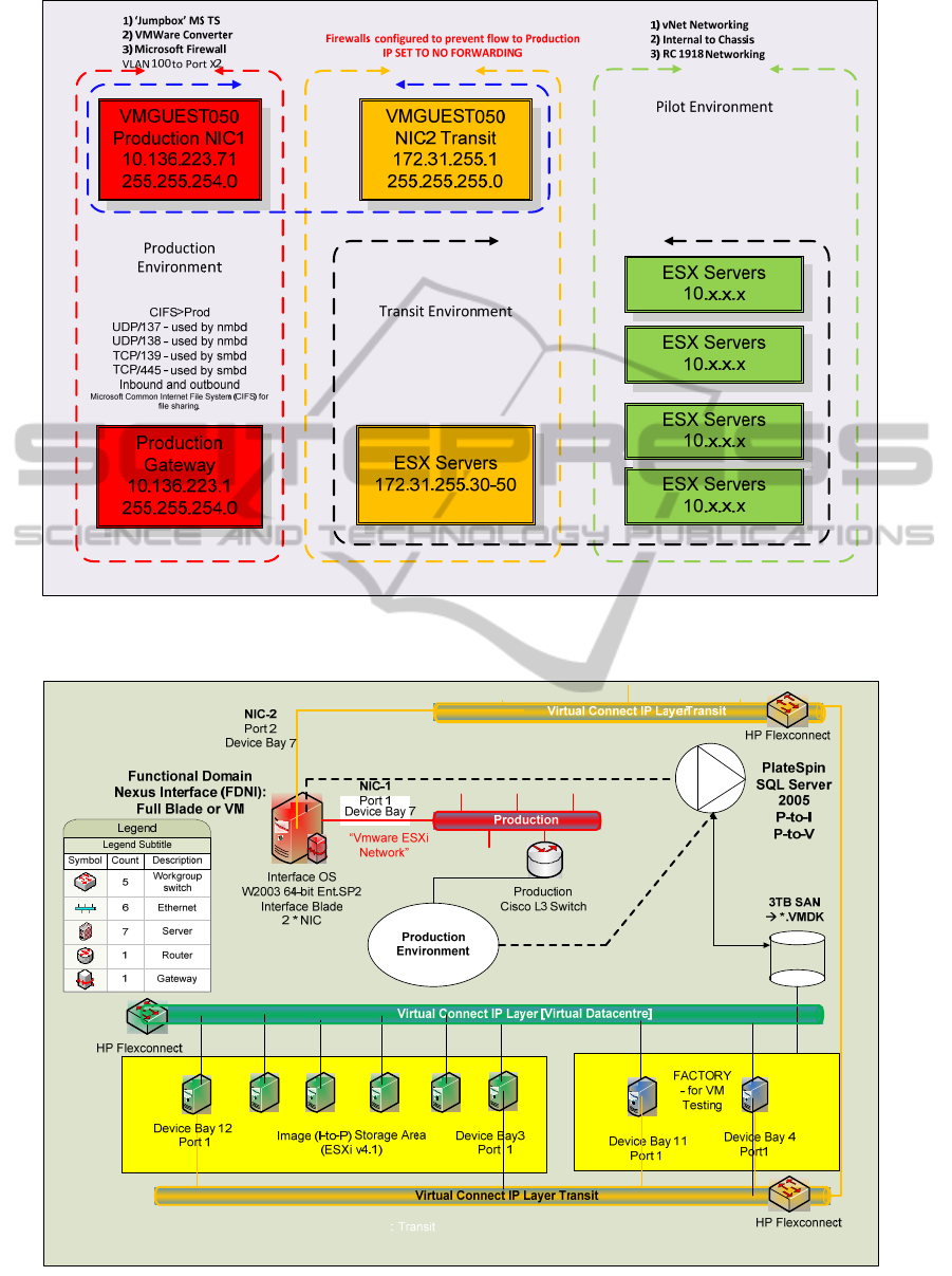
Figure 5: A summary illustration of the FDNI that shows the basic parameters that are involved in the interfacing between
the Production, the Transit and the FD (Pilot) environments.
Figure 6: View of the initial 'Superhost' structure showing the interface between the Production, the Transit and the FD (in
this case the Virtual Datacentre) environments.
APRACTICALIMPLEMENTATIONOFAFUNCTIONALDOMAINWITHINACLOUD
21
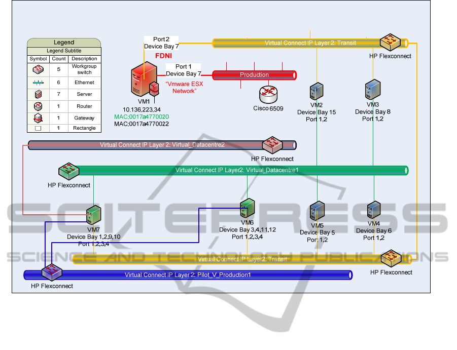
Figure 7: The addition of more Virtual Ethernets to the FD. These can only be accessed from the ‘Transit’ Virtual Ethernet
employing TCP/IP L2 using the 4 vNIC ports in any of the local VMs.
The FDNI is connected to the exit port via NIC-2 of
the blade, which is in turn connected to the ‘Transit’
virtual Ethernet. As the name implies, all constituent
HP BL490c blades in their respective clusters within
the FD have one of their two NIC’s connected to the
‘Transit’ virtual Ethernet. This gives a method of L2
TCP/IP connection for all VMs / VAs that are
installed in the FD. However, not all installed VMs
require direct connectivity to the ‘Transit’ virtual
Ethernet. It is only important that there is a route that
can be taken by L2 to ‘Transit’ at this point. The
next level of development is to use the latter L2
connectivity to facilitate the addition of further
virtual Ethernets (e.g. Virtual_Datacentre2,
Pilot_V_Production1 in Figure 7) using HP c7000
VC software.
This is now complemented by the addition of an
extra virtual Ethernet for the hosting of a set of VDIs.
The VDIs are communicated with via the FDNI
using the RDP (Microsoft). When activated the user
has access to a remote desktop window which
operates inside the FD / PoC, and with this the user
may operate safely without any risk that his/her
activities may compromise the functionality or the
integrity of the external cloud. The FD design is now
taken to a further level by the addition of a L3
switch, which is implemented by using a VM with a
Red Hat Linux guest operating system together with
a FreeSCO L3 switch command system. This now
results in the design model of Figure 8. This has
resulted in the use of VAs to enable a DMZ to be
constructed (Figure 9). The totality of these
incremental layers of development is now available
using L3, and also using uplinks to the 3X, 4X or 5X
HP c7000 VC ports to the Cisco Ethernet networks.
This leads to the extension of the design concept
in that the overall FD can access an isolated Ethernet
that runs between the two sites. As such it is
important to understand that the Ethernet concerned
must be isolated from the main network, so that
there may be no interference with respect to the
traffic or the TCP/IP addressing ranges. Thus, this
requirement is met by the set of two FDs illustrated
in Figure 10.
Therefore the next area of innovation is to enable
a VDI layer virtual Ethernet to give a layer of secure
access from the Cisco-based production network in a
transparent manner through an uplink from the
chassis (Figure 10) to the Cisco L3 switch layer.
This results in the FD being extended so that it is
still bounded by the FDNI_entry and the FDNI_exit
but now extends between the two sites in a seamless
CLOSER2012-2ndInternationalConferenceonCloudComputingandServicesScience
22
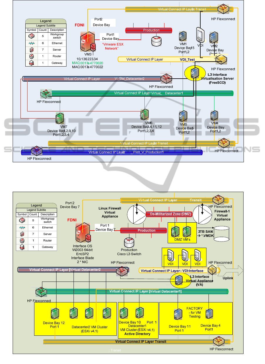
Figure 8: The addition of an extra VDI virtual Ethernet as well as additional production emulation layers within the FD.
These inter-communicate using TCP/IP L2. The addition of TCP/IP L3 switching capability to this set of virtual Ethernets
is done by creating a VA--based on Red Hat Linux using the FreeSCO L3 switch software.
Figure 9: The addition of a De-Militarised Zone (DMZ) made up of Linux-based VA Firewall units on a separate DMZ
virtual Ethernet, and a L3 switch to link all of the FD virtual Ethernets.
APRACTICALIMPLEMENTATIONOFAFUNCTIONALDOMAINWITHINACLOUD
23
Figure 10: Extended cross-site virtualized FD (PoC).
fashion. This has been done using a stretched VLAN
between sites to maintain the same subnet and
gateway address, but this technique only works
where the physical connectivity distance between
the sites is less than of the order of 20km. If
stretched VLANs were replaced by L3 switching,
then the FD network could still be isolated but the IP
addresses of the constituent FD elements will be
different on each of the respective sites.
This does not mean that this design no longer
works, but rather that the mapping models in Figure
2, Figure 3 and Figure 4 must be accurately detailed
so that the IP addressing of each VM on each site is
categorized and implemented through the use of
DHCP / DNS. This design enables users to use the
VMs / VAs either directly through the specific use
of RDP from the Production network through the
FDNI, or via controlled access of the VDIs via the
uplink interface from the isolated test virtual
Ethernet to the HP c7000 VC. This is extended to
operate on a WAN-based cross-site basis as shown
in Figure 10. This can now include physical devices
as well as VMs / VAs.
This design enables the testing of a set of specialised
applications with an HP Superdome and a SUN
F15K using the FD PoC environment adapted so as
to isolate the physical server components of the
required applications. The physical and virtual
servers are implemented using the current IP
addresses of their equivalent Production hosts due to
the capabilities of the FDNI.
4 DISCUSSION
It is envisaged that each such subsystem may be
represented within an FD with the contents of each
such subsystem making up an individual distributed
application. From this paper it can be seen that such
contents could be either virtual or physical. This
technology introduces a practical means of
implementing ‘Systems Engineering depth to
breadth switching’ which is broadly defined as “The
ability of systems engineers and architects to
cognitively alternate, from a detailed engineering
discipline rigor, to a meaningful broad level of
abstraction. These unique individuals have the
ability to build models that hide underlying
implementation details and bridge the
communication gaps between multiple disciplines.”
(Trowbridge et al., 2003). Each such subsystem
modelled within an FD should be able to be
represented as a single class comprised of a set of
constituent classes. The relationship to be pursued
here is not one of inheritance as in a superclass to a
set of subclasses (Muller, 2007, Shannon, 2000) but
rather one employing the techniques of frame-based
modelling (Minsky, 1974, Karp, 1992) to produce a
framework class to represent the knowledge of how
the system is constructed.
Site 2
Isolated Test VLAN
DC / DNS/ DHCP
Superdome
(if VM)
HP XP
Isolated Transit LAN
Wintel App
Servers
(if VM)
FDNI-2
RDP VM
Isolated Transit LAN
FDNI-1
Isolated Test VLAN
Wintel App
VM’s
Isolated Test VLAN uplinked to
X4
10Gbs Max
SuperDome
vProduction2 uplinked
to X4
10Gbs Max
SuperDome
Stretched VLAN
10.0.0.8,
255.0.0.0
(Isolated Test
VLAN)
L3 Virtual Ethernet
Isolated VLAN
Virtual Ethernet
VDI
Wintel SQL
Server Servers
(if VM)
RDP
X3 X4 X5 X3
X4
X5
L3 Virtual Router
Appliance
L3 Virtual Router
Appliance
Virtual Connect Ports
Virtual Connect Ports
Production Network
CISCO STRETCHED|VLAN Isolated Testing Network for Advanced Distributed Applications / HP Superdome / SUN F15K
Superdome
(Physical)
Isolated Test
VLAN uplinked
to X4
10Gbs
Max
SuperDome
Site 1
X3,X4, X5 =
10Gbps
Ethernet
CLOSER2012-2ndInternationalConferenceonCloudComputingandServicesScience
24

5 FUTURE WORK
This area of integration is carried out within a single
HP c7000 chassis and extended across multiple
chassis units to form a distributed centre capable of
supporting in the order of more than 1000 VMs.
Further work is required in building a fully
integrated model with distributed sets of chassis
units that are linked using L3 TCP/IP with DHCP /
DNS / X.500-based directory services to facilitate
the dynamic movement of VMs that are within the
same FD, but are actually located on different sites.
This work also needs to be extended in applying
different classes of QMS Requirement-based
Clustering (Codina et al., 2007) to the multi-cluster
blade model within the ‘SuperHost’, enabling
different ‘SuperHost’ entities to be clustered in
different manners (Kim and Han, 2007) according to
the QMS Requirements specified. This leads
towards using the ‘SuperHost’ system as a key
component in a practical solution to cloud
computing. The principle here is that an FD could be
used to enable a set of pattern-based design tools to
create a practical means of designing and modelling
systems (Hohpe and Woolfe, 2004, Shannon and
Hapner, 2000), from the simple to the very complex.
Such systems, through the use of associated
metadata, could also have the capability of
interfacing to complex simulation systems based on
describing systems in terms of specific class-based
connectivity, such as Hyperformix. Creating
multiple sets of overlapping FDs for accelerated
policy simulation and system modelling is another
area that is being currently pursued. This can be
done through the use of mathematics followed by
the creation of VMs as simulated application
servers. This will create overlapping models where
the resultant effect on the net policies can be
virtualized.
NB. All hardware devices mentioned in this paper
can be replaced by analogous ones with minimal
modifications to all configurations.
6 CONCLUSIONS
This paper presents the basis for advancing the
concept of the metamodel that involves the concept
of moving from a set of modelling methods within a
framework methodology (Fayed et al., 2000) to an
equivalent model that is virtual and can participate
in positive testing and evaluation before the main
product is finally constructed, thereby lowering the
overall cost and risk involved in a development
project.
REFERENCES
Caetano, A., Pombinho, J., Tribolet, J., 2007 In
Representing Organizational Competencies, SAC’07
(ACM), pp.1257-1262.
Carman, C., 2001 Applying UML and Patterns (2
nd
Ed),
Prentice Hall.
Codina, J. M., Sanchez, J., Gonzalez, A., 2007 Virtual
Cluster Scheduling Through the Scheduling Graph. In
International Symposium on Code Generation and
Optimization (CGO'07) (IEEE), pp.89-101.
Conrad , J., Dengler, P., 2000 Introducing .NET, WROX
Pub.
Corn, C., Mayfield, V., 1998 COM / DCOM Primer Plus,
SAMS.
Daniels, J., 2009 Server Virtualization Architecture and
Implementation, ACM Crossroads, 16 (1), pp.8-12
Eccles, J,.,Loizou, G., 2011 Functional Domain Concepts
in the Modelling of Cloud Structures and the
Behaviour of Integrated Policy-Based Systems
Through the use of Abstraction Classes, In 1
st
International Conference on Cloud Computing and
Services Science (CLOSER 2011), Noordwijerhout,
The Netherlands, 7-9
th
May 2011, pp.86-97.
Eccles, J., Loizou, G., (in preparation_a) A Methodology
to Control the Production of a Practical Virtual
Environment for a Cloud in an Optimal Manner from a
Complex Physical Environment.
Eccles, J., Loizou G., (in preparation_b) An Extended
Methodology to Integrate Multiple Functional
Domains within a Virtualized Environment by
enhancing the Functional Modelling of the Nexus
Interface units.
Farley, J., 1998 Java Distributed Computing, O’Reilly.
Fayed, M. E., Johnson, R. E., 2000 Domain-Specific
Application Frameworks, Wiley.
Hohpe, G., Woolf, B., 2004 Enterprise Integration Patterns,
Addison-Wesley.
Traore, I., Aredo,D. B., Ye, H., 2003 An Integrated
Framework for Formal Development of Open
Distributed Systems. ACM Symposium on Applied
Computing (SAC2003), pp.1078-1085.
Karp, P.D., 1992 The Design Space of Frame Knowledge
Representation Systems, SRI International Technical
Note No 520, Artificial Intelligence Centre,
Computing and Engineering Sciences Division.
Kim, Gui-Jung., Han, Jung-Soo., 2007 The clustering
algorithm of design pattern using object-oriented
relationship. In Proceedings of the 2007 international
conference on Computational Science and its
Applications (ICCSA’07)- Volume Part III, Springer-
Verlag Berlin, Heidelberg, pp. 997-1006.
Loy, I., Galan, F., A.Sampaio, Gill, V., Rodero-Merino,
L.,, 2009 Service Specification in Cloud Environments
Based on Extensions to Open Standards. ACM
APRACTICALIMPLEMENTATIONOFAFUNCTIONALDOMAINWITHINACLOUD
25

Communication System Software and Middleware
(COMSWARE 09), Dublin, Ireland.
Menasce, D.A., Almeisida, V.A., 2004 Performance by
Design, Prentice Hall.
Minsky, M., 1974 A Framework for Representing
Knowledge, MIT-AI Laboratory Memo 306.
Mowbry, T. J., Malveau, R. C., 1997 Corba Design
Patterns, Wiley Computer Publishing.
Muller, P., 1997 Instant UML, Woz Press.
Niculescu, V., Moldovan, G., 2005 Building an Object
Oriented Computational Algebra System Based on
Design Patterns, In Proceedings of the Seventh
International Symposium on Symbolic and Numeric
Algorithms for Scientific Computing (SYNASC '05),
IEEE Computer Society Washington, DC, USA, pp.8.
Otte, R., Patrick, P., Roj, M., 1996 Understanding Corba
(Common Object Request Broker Architecture),
Prentice Hall.
Shannon, B., Hapner. M., 2000 Java 2 Platform Enterprise
Edition – Platform and Component Specification,
Addison Wesley.
Solomon, B., Ionescu, D., 2007 Real-Time Adaptive
Control of Autonomic Computing Environments, IBM
Centre for Advanced Studies, Toronto, pp. 1-13.
Trowbridge, D., Mancini D., Quick, D., Thoughtworks
Inc., 2003 Enterprise Solution Patterns using
Microsoft.NET, Version 2.0, Microsoft Press.
VMware Corporation, 2006 VMware Server
Administration Guide 1.0 VMware Inc. Available
from: http://www.vmware.com/support/pubs.
CLOSER2012-2ndInternationalConferenceonCloudComputingandServicesScience
26
