RENDERING VIRTUAL OBJECTS INTO REAL SCENE
BY USING A DIFFUSE SPHERE
Yuji Kanda
1
, Fumihiko Sakaue
1
, Jun Sato
1
, Kazuhisa Ishimaru
2
and Masayuki Imanashi
3
1
Nagoya Institute of Technology, 466-8555 Nagoya, Japan
2
NIPPON SOKEN Inc., 445-0012 Nishio, Japan
3
DENSO Corporation, 448-8661 Kariya, Japan
Keywords:
Augmented Reality, Diffuse Sphere, Light Source Distribution, Shading, Shadows.
Abstract:
In this paper, we propose an efficient method for rendering virtual objects into real scene images. We put a
diffuse sphere into the scene as a reference object, and use the direct relationship between the intensity of the
diffuse sphere and the intensity of virtual objects for rendering the virtual objects in images. We also generate
shadows of the virtual objects by using shadows of the reference sphere. As a result, arbitrary virtual objects
and their shadows can be rendered quite efficiently from a single diffuse sphere put in the scene. The proposed
method is tested in real image experiments, and evaluated quantitatively comparing with the existing method.
1 INTRODUCTION
Rendering virtual objects into real scenes is very use-
ful for making movies and for designing augmented
reality systems. For generating realistic augmented
reality images, it is very important to generate accu-
rate shade and shadow of virtual objects in images.
The existing methods generate shade and shadow
of objects by estimating light source distributions of
the scene (Marschner and Greenberg, 1997). The
spherical mirror is often used for measuring light
source distributions (Debevec, 1998; Kanbara and
Yokoya, 2004). In these methods, a camera observes
the spherical mirror put in the scene, and the light
source distributions are measured from the camera
image directly. Although these methods are simple
and efficient, cameras in general do not have enough
dynamic range to measure the light source distribu-
tions directly. Thus, these methods require to take
multiple images changing the shutter speed of the
camera. For solving the problem, known diffuse ob-
jects such as diffuse spheres were also used for esti-
mating the light sources (Zhang and Yang, 2001; Wei,
2003; Takai et al., 2004; Weber and Cipolla, 2001).
These methods use the boundary lines on diffuse ob-
jects, which separate illuminated and un-illuminated
areas for estimating light source orientations. How-
ever, extracting these boundary lines on diffuse ob-
jects is not easy in practice. Furthermore, it is diffic-
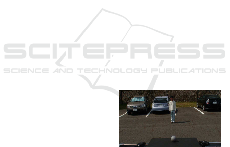
Figure 1: The reference sphere and a plane put in the scene.
We use a diffuse sphere and a plane for generating shading
information and shadows of virtual objects.
ult for these methods to estimate light source distribu-
tions which consist of many light sources. As shown
in these research, accurate estimation of light source
distributions is not easy in practice.
Thus, we in this paper propose an efficient
method for rendering virtual objects into real scenes
without estimating light source distributions as far as
possible. In our method, we use a diffuse sphere put
in the scene as a reference object as shown in Fig. 1.
Our method separates the task of shading and the task
of shadowing. We separate these two tasks, since we
generate shading information without estimating light
source distributions of the scene, while we generate
shadows by estimating the light source distributions.
For generating shading information of virtual ob-
279
Kanda Y., Sakaue F., Sato J., Ishimaru K. and Imanishi M..
RENDERING VIRTUAL OBJECTS INTO REAL SCENE BY USING A DIFFUSE SPHERE.
DOI: 10.5220/0003850202790285
In Proceedings of the International Conference on Computer Vision Theory and Applications (VISAPP-2012), pages 279-285
ISBN: 978-989-8565-03-7
Copyright
c
2012 SCITEPRESS (Science and Technology Publications, Lda.)

jects, we use the direct relationship on intensity be-
tween the virtual object and the diffuse sphere. The
proposed method is very efficient and reasonably ac-
curate, since this method does not need to estimate
light source distributions, and does not suffer from the
estimation error of light source distributions.
For generating the shadow of virtual objects, we
use the shadow of reference diffuse sphere. If we
have a known object on a ground plane, the shadow
of the object on the plane is a very useful cue to esti-
mate light source distributions. Sato et al. (Sato et al.,
2003) proposed a method for estimating light source
distributions from shadows on a plane, which are gen-
erated by known objects. However, their method as-
sumes that there is no inter reflection between the ob-
ject and the plane. Hence, their method suffers from
the inter reflections, if the reflectance of the object is
large. Thus, we in this paper estimate light source
distributions from shadows of a diffuse sphere taking
account of the effect of inter reflections between the
sphere and the plane. As a result, virtual objects and
their shadows can be rendered quite efficiently and ac-
curately from a single diffuse sphere put in the scene.
In the following sections, we first propose an ef-
ficient method for generating shading information of
virtual objects from a reference diffuse sphere with-
out using light source information. We next propose
a method for generating shadows by estimating light
source distributions from the shadow of the reference
sphere. We in this paper assume all the light sources
are at infinity, and virtual objects put into the scene do
not emit any light and are Lambertian.
2 SYNTHESIZING VIRTUAL
OBJECTS INTO THE SCENE
The standard method for synthesizing virtual objects
into real scene is based on the estimation of light
sources of the scene. Suppose we have M light
sources at infinity, whose directions are represented
by unit vectors s
k
(k = 1, ··· , M), and magnitudes are
E
k
= [E
R
k
, E
G
k
, E
B
k
]
⊤
(k = 1, ··· , M) in red, green and
blue color channels. If the object surface is Lamber-
tian, the image intensity I
i
= [I
R
i
, I
G
i
, I
B
i
]
⊤
of ith point
on the surface illuminated by E
k
(k = 1, ··· , M) can
be described as follows:
I
i
=
M
∑
k=1
CR
i
E
k
v
ik
n
⊤
i
s
k
(1)
where n
i
denotes the surface normal at the ith point,
and v
ik
denotes a visibility function, which takes 1 if
the ith point is illuminated from the kth light source,
and takes 0 in the other case. R
i
is a 3 × 3 diag-
onal matrix whose diagonal components are the re-
flectance of the surface point ρ
R
i
, ρ
G
i
, ρ
B
i
in R, G and
B components as follows:
R
i
=
ρ
R
i
0 0
0 ρ
G
i
0
0 0 ρ
B
i
(2)
C denotes the characteristic function of the camera,
which represents the response of the camera in R, G
and B channels, i.e. the gain of output signals with re-
spect to input signals. In general the crosstalk among
R, G and B channels is very small and negligible, and
thus we assume the matrix C is also diagonal as fol-
lows:
C =
C
R
0 0
0 C
G
0
0 0 C
B
(3)
where, C
R
, C
G
and C
B
denote gains in each channel.
We in this paper assume that the gamma correction
does not exist in the camera, and its characteristic
function is linear.
From (1), we find that we need light source in-
formation E
k
in each orientation s
k
and camera char-
acteristics C for synthesizing the image intensity of
virtual objects. Thus, the existing methods estimate
light source information of the scene by using various
cues, such as shadows and shading, and measure the
characteristic function of the camera by using color
chart etc. However, the results suffer from the mea-
surement errors of these components.
Thus, we in this paper propose a method which
enables us to compute the image intensity of virtual
objects without estimating light sources and camera
characteristic functions. In our method, we put a dif-
fuse sphere in the scene as a reference object as shown
in Fig. 1, and use its image information for synthesiz-
ing virtual objects into the scene. Since the sphere has
surface normals in all the directions, the surface nor-
mal of any point on a virtual object in the scene has
its reference surface normal on the sphere. Although
not all the surface normals are visible in a single cam-
era image, all the visible surface normals of virtual
objects have their references in the visible part of the
sphere, if we assume affine projection.
Now, let us consider an image intensity I
′
j
of a jth
point on the reference sphere, whose surface normal
n
′
j
is identical with the surface normal n
i
of ith point
on the virtual object, i.e. n
′
j
= n
i
. Then, I
′
j
can be
described as follows:
I
′
j
=
M
∑
k=1
CR
′
j
E
k
v
′
jk
n
⊤
i
s
k
(4)
VISAPP 2012 - International Conference on Computer Vision Theory and Applications
280

where, R
′
j
is the reflectance matrix of the jth point on
the reference sphere, and v
′
jk
is a visibility function of
the point with respect to the kth light source. If the
object is convex, v
ik
is identical with v
′
jk
. If the object
is not convex, v
ik
is not completely identical with v
′
jk
.
However, in most of the case, v
ik
is close to v
′
jk
. Thus,
we in this paper assume v
ik
and v
′
ik
are identical.
Since both C and R are diagonal, (1) and (4) can
be described as follows:
I
i
= R
i
L (5)
I
′
j
= R
′
j
L (6)
where,
L =
M
∑
k=1
CE
k
v
ik
n
⊤
i
s
k
(7)
From (5) and (6), we find that the image intensity I
i
of the virtual object can be computed from the image
intensity I
′
j
of the reference sphere as follows:
I
i
= R
i
R
′
j
−1
I
′
j
(8)
As a result, we do not need to estimate light source
distributions nor characteristic function of cameras
for synthesizing virtual objects into the real scene im-
ages. Thus, the proposed method is very simple and
efficient.
Since the image of the reference sphere is digital
and the surface normals of the reference sphere are
discrete in practice, we compute the image intensity
I
′
j
of a point on the reference sphere, whose surface
normal is identical with that of the virtual object, by
using the linear interpolation. To ensure a reasonable
accuracy of synthetic image generation, the reference
sphere in the image should not be too small.
3 SYNTHESIZING SHADOW OF
VIRTUAL OBJECTS
We next consider a method for generating shadow of
objects. For realistic virtual images, it is very impor-
tant to generate realistic shadows on the floor. We
generate shadow of virtual objects by using the same
reference sphere used for shading virtual objects.
Suppose the reference sphere is put on a planar
Lambertian surface. Then, the shadows of the sphere
appears on the planar surface, and they are visible
from the scene camera. These image shadows pro-
vide us useful information for generating the shadows
of virtual objects put in the scene. Sato et al. (Sato
et al., 2003) proposed an efficient method for estimat-
ing light source distributions from shadows of scene
Figure 2: Sampling of light source distributions on a
geodesic dome. Each patch on the dome represents the di-
rection of each light source.
objects. We extend their method for estimating light
source distributions and generating shadows from the
reference sphere. Sato et al. assumed that there is
no inter reflection between the scene objects and the
planar surface, and estimated the light source distri-
bution from the shadows of the scene objects on the
planar surface. This assumption is reasonable if the
reflectance of objects is small, and the form factors
between the object and the plane are also small. The
form factor is the visibility between two patches on
surfaces, and it becomes large if the relative orienta-
tion between normals of these two patches is close to
π radian and these patches are close to each other. In
our method, we use a reference sphere put on a plane.
The reference sphere and the plane are very close to
each other at around the contact point of these two ob-
jects. Furthermore, the relative orientation of two sur-
faces is close to π radian at around the contact point.
Thus, inter reflections are not negligible in the esti-
mation of light source distributions. Therefore, we
propose a method for estimating light source distribu-
tions and generating shadows taking account of inter
reflections.
3.1 Sampling of Light Source
Distribution
In order to estimate light source distributions under
multiple lights, we represent the light source distribu-
tions by using a geodesic dome as shown in Fig.2. In
this model, a light source distribution is represented
by the magnitude of light source E
k
= [E
R
k
, E
G
k
, E
B
k
]
⊤
(k = 1, ··· , M) in M light source directions s
k
(k =
1, ··· , M), which are represented by M patches on
the geodesic dome. Since s
k
(k = 1, · ·· , M) is prede-
fined on the geodesic dome, the estimation of a light
source distribution is same as the estimation of E
k
(k = 1, ··· , M).
RENDERING VIRTUAL OBJECTS INTO REAL SCENE BY USING A DIFFUSE SPHERE
281

3.2 Light Source Distributions from
Shadows of Reference Objects
Let us consider a reference object, which consists of a
sphere and a plane with known reflectance, as shown
in Fig. 1. Although many other objects exist in the 3D
space, we consider these other objects as light sources
at infinity, and these light sources illuminate the ref-
erence object. Hence, the inter reflection occurs be-
tween the reference sphere and the reference plane,
but it does not occur between the reference object and
other objects in the 3D space. This assumption is
valid in most of the case, since the distance between
the reference object and other objects are much larger
than the distance between the reference sphere and
the reference plane in general. Thus, we model the
3D world by the reference object and light sources at
infinity, which are represented by a geodesic dome.
Suppose we have N patches on the reference ob-
ject, and M patches on the geodesic dome. Then, M
patches on the geodesic dome emit light, and the inter
reflection occurs among N patches on the reference
object. Then, the following radiosity equation holds:
I
i
=
N
∑
j=1
F
ij
R
i
I
j
+
M
∑
k=1
G
ik
CR
i
E
k
(9)
where, the first term in the right side of (9) represents
the inter reflection and the second term represents the
direct illumination by light sources on the geodesic
dome.
F
ij
denotes the form factor between ith and jth
patches on the reference object, and G
ik
denotes the
form factor between ith patch on the reference object
and kth patch on the geodesic dome. These are de-
scribed as follows:
F
ij
=
A
j
v
ij
cosθ
i
cosθ
j
πr
2
(10)
G
ik
=
A
k
v
ij
cosθ
i
π
(11)
where, A
i
denotes the area of ith patch, and θ
i
denotes
the angle between the surface normal of ith patch and
a ray between two patches. r is the distance between
two patches. Note, r
2
term does not exist in G
ik
, since
each patch on the geodesic dome represents a light
source at infinity, and its energy does not decrease
with respect to the distance r. Also, each patch on the
geodesic dome is front-parallel, and thus cosθ
k
= 1.
This is why cosθ
k
does not exist in (11).
Since we have N patches on the reference object
and M patches on the geodesic dome, we can derive
the following system of linear equations from (9).
G
11
R
1
··· G
1M
R
1
.
.
.
.
.
.
G
N1
R
N
··· G
NM
R
N
E
′
1
.
.
.
E
′
M
=
I
1
−
∑
F
1j
R
1
I
j
.
.
.
I
N
−
∑
F
N j
R
N
I
j
(12)
where, E
′
k
is a light source distribution multiplied by
the camera characteristic function C as follows:
E
′
k
= CE
k
(k = 1, ··· , M) (13)
We in this paper estimate E
′
k
instead of E
k
, which en-
ables us to generate virtual shadows without knowing
camera parameters C. If N ≥ M, we can estimate the
light source distribution E
′
k
(k = 1, · ·· , M) by solving
(12) taking account of the inter reflection between the
reference sphere and the reference plane.
3.3 Synthesizing Shadows
Once the light source distribution is estimated, the
shadow of virtual objects can be generated from the
distribution.
Let us consider an image point P in the ith patch
on the ground plane, whose image intensity is I
P
and
reflectance is R
P
. Let G
ik
be the form factor between
the ith patch on the ground plane and kth patch on the
geodesic dome before putting virtual objects, and let
G
′
ik
be that after putting the virtual objects. Both G
ik
and G
′
ik
can be computed easily from the geometric
relationship between the virtual objects and the light
source directions. Then, if we neglect inter reflec-
tions, the image intensities of point P before and after
putting the virtual objects are described as follows:
I
P
=
M
∑
k=1
G
ik
R
P
E
′
k
(14)
= Dr
P
(15)
I
′
P
=
M
∑
k=1
G
′
ik
R
P
E
′
k
(16)
= D
′
r
P
(17)
where, D and D
′
are diagonal matrices, whose diag-
onal components are
∑
M
k=1
G
ik
E
′
k
and
∑
M
k=1
G
′
ik
E
′
k
re-
spectively, and r
P
is a three vector which consists of
the three diagonal components of R
P
.
Then from (15) and (17), we find that the image
intensity I
′
P
of point P after putting the virtual objects
can be computed from the image intensity I
P
of the
point before putting the virtual objects as follows:
I
′
P
= D
′
D
−1
I
P
(18)
As shown in (18), the image intensity of shadows can
be computed without knowing reflectance R
P
of the
ground plane and camera parameters C.
VISAPP 2012 - International Conference on Computer Vision Theory and Applications
282
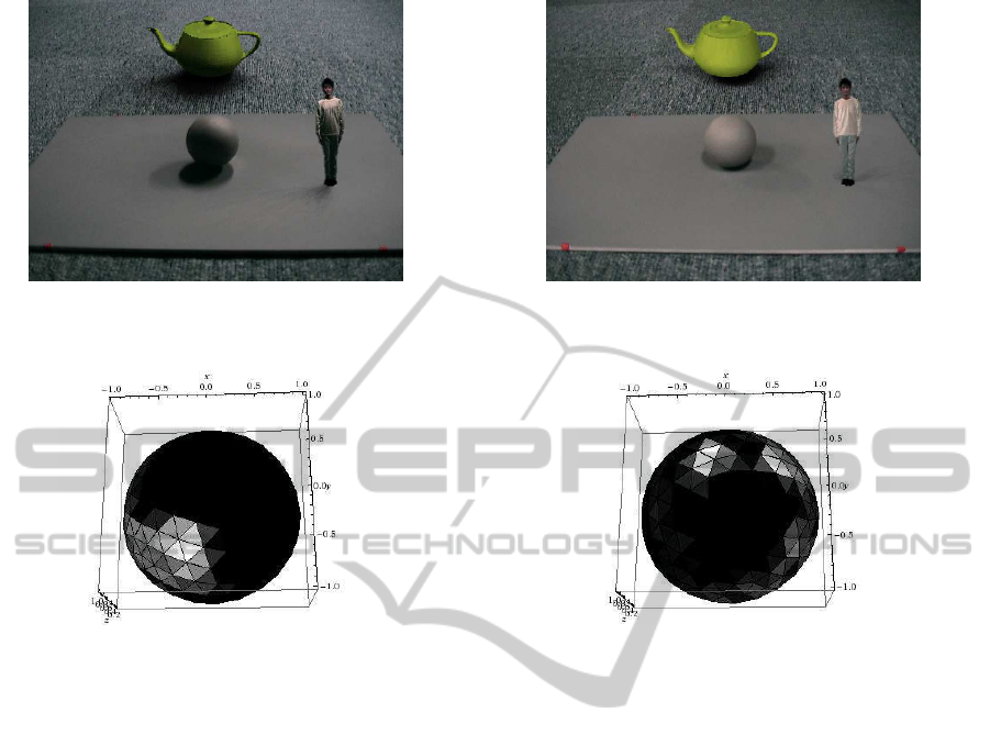
Figure 3: The image of the reference sphere and synthesized
virtual objects (person, pod).
Figure 4: The light source distribution estimated from Fig. 3
by using the proposed method.
4 EXPERIMENTS
4.1 Real Image Experiments
We next show the results of some real image exper-
iments. In these experiments, we synthesize virtual
objects into real scene images. The virtual objects
are rendered by using the method shown in section 2,
and their shadows are rendered by using the method
shown in section 3.
Fig. 3 shows the image of a reference sphere and a
reference plane. The intensity of the sphere was used
for rendering virtual objects into the image, and the
shadow of the sphere was used for estimating the light
source distributions and rendering shadows of the vir-
tual objects into the image. Fig. 4 shows the light
source distribution estimated from Fig. 3 by using the
proposed method. The light source distribution was
measured at 225 points on the geodesic dome. Fig. 3
shows virtual objects (i.e. person, pod) and their shad-
ows rendered by using the proposed method. Fig. 5
and Fig. 6 show another example of image synthesis
under a different light source distribution. As shown
in these figures the shade and shadow of the virtual
Figure 5: The image of the reference sphere and synthesized
virtual objects (person, pod).
Figure 6: The light source distribution estimated from Fig. 5
by using the proposed method.
objects were generated properly, although the light
source distributions of the scene are very complex.
4.2 Accuracy Evaluation
We next evaluatethe accuracy of the proposed method
comparing with other methods. In this evaluation, we
use synthetic images for quantitative evaluation.
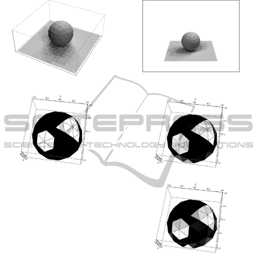
Fig. 7 shows the synthetic 3D scene of the ref-
erence object used in our experiments. The refer-
ence sphere and the plane are Lambertian and their
reflectance is 0.6 in R, G and B. The light source dis-
tribution used for generating the scene is shown in
Fig. 8. There are 75 light sources on the geodesic
dome. Fig. 9 shows an image of the scene observed by
a virtual camera. The number of the observed patches
of the reference object was 83, and that of the ground
plane was 374. The Gaussian image noises with the
standard deviation of 1.0 were added to the image in-
tensity of each point, while the range of image inten-
sity is from 0 to 255. We estimated the light source
distribution of this scene from the image shown in
Fig. 9 by using the proposed method. We also esti-
mated the light source distribution by using the exist-
ing method proposed by Sato et al. (Sato et al., 2003)
for comparison.
RENDERING VIRTUAL OBJECTS INTO REAL SCENE BY USING A DIFFUSE SPHERE
283
-2
0
2
x
-2
0
2
y
0.0
0.5
1.0
1.5
2.0
z
Figure 7: 3D scene used in our simulation experiments.
Figure 8: The light source distribution used in the simula-
tion experiments.
Fig. 10 (a) shows the light source distribution es-
timated by using the proposed method, and Fig. 10
(b) shows that of the existing method. From Fig. 10
and Fig. 8, we find that the proposed method provides
us better estimation of light source distribution com-
paring with the existing method. The RMS error of
the estimated light source distribution divided by the
maximum ground truth light source magnitude was
0.14 in the proposed method and was 0.40 in the ex-
isting method.
We next evaluated the accuracy of estimated light
source distribution changing the reflectance of the
reference object. Fig. 11 shows the RMS error of
light source distributions estimated from the proposed
method and the existing method. The horizontal axis
shows the reflectance of the reference object, and the
vertical axis shows RMS error divided by the maxi-
mum light source magnitude. As shown in this figure,
if the reflectance of the reference object is small, the
error of estimation is small in both methods. How-
ever, if the reflectance of the reference object is large,
the accuracy of the existing method (Sato et al., 2003)
degrades drastically, while the proposed method still
provides us good accuracy. This is because the ex-
isting method suffers from inter reflections, when the
reflectance of the reference object is large.
Figure 9: The synthetic image generated by projecting the
3D scene shown in Fig. 7.
(a) Proposed method.
(b) Existing method.
Figure 10: The light source distribution estimated by using
the proposed method (a) and the existing method (b). The
ground truth is shown in Fig. 8.
5 CONCLUSIONS
In this paper, we proposed an efficient method for
synthesizing virtual objects into real scene images
by using a diffuse reference sphere. The proposed
method uses the direct relationship between the inten-
sity of the reference sphere and the intensity of virtual
objects for generating the shading information of ob-
jects. Also, the proposed method generate shadows of
VISAPP 2012 - International Conference on Computer Vision Theory and Applications
284

0.0 0.1 0.2 0.3 0.4 0.5 0.6 0.7
reectanc
e
0.0
0.2
0.4
0.6
0.8
1.0
error
Figure 11: The accuracy of estimated light source distribu-
tions. If the reflectance of the reference object is large, the
accuracy of the existing method (Sato et al., 2003) degrades
drastically, while that of the proposed method does not.
the virtual objects by using the shadows of the refer-
ence sphere. As a result, the virtual objects and their
shadows can be rendered quite efficiently from a sin-
gle diffuse sphere put in the scene.
We tested the proposed method by using real
scene images. We also evaluated the accuracy of
the proposed method by using a synthetic 3D scene
comparing with the existing method. The proposed
method can synthesize virtual objects quite efficiently
with reasonable accuracy, and thus it is very useful.
The future work includes the extension of the pro-
posed method to the video streams, so that moving
virtual objects and their shadows are rendered prop-
erly into real scene videos.
REFERENCES
Debevec, P. (1998). Rendering synthetic objects into real
scenes: Bridging traditional and image-based graphics
with global illumination and high dynamic range pho-
tography. In Proc. SIGGRAPH 98, pages 189–198.
Kanbara, M. and Yokoya, N. (2004). Shadow representation
for augmented reality by estimating light environment
and shape of real scene. In Proc. MIRU, volume 2,
pages 247–252.
Marschner, S. and Greenberg, D. (1997). Inverse lighting
for photography. In Proc. Color Imaging Conference,
pages 262–265.
Sato, I., Sato, Y., and Ikeuchi, K. (2003). Illumination from
shadows. IEEE Transaction on Pattern Analysis and
Machine Intelligence, 25(3):290–300.
Takai, T., Nishimura, K., Maki, A., and Matsuyama, T.
(2004). Difference sphere: an approach to near light
source estimation. In Proc. IEEE Conference on Com-
puter Vision and Pattern Recognition, pages 98–105.
Weber, M. and Cipolla, R. (2001). A practical method for
estimation of point light sources. In Proc. British Ma-
chine Vision Conference, pages 471–480.
Wei, J. (2003). Robust recovery of multiple light source
based on local light source constant constraint. Pattern
Recognition Letters, 24(1–3):159–172.
Zhang, Y. and Yang, Y. (2001). Multiple illuminant di-
rection detection with application to image synthesis.
IEEE Transaction on Pattern Analysis and Machine
Intelligence, 23(8):915–920.
RENDERING VIRTUAL OBJECTS INTO REAL SCENE BY USING A DIFFUSE SPHERE
285
