
Towards Domain-specific Modeling for Java Enterprise
Applications
Moritz Balz and Michael Goedicke
Paluno – The Ruhr Institute for Software Technology
University of Duisburg-Essen, Campus Essen, Germany
Abstract. Enterprise Applications are usually developed in the context of cer-
tain frameworks and platforms, for example the Java Enterprise Edition. These
environments determine specific software architectures for such applications with
respect to modularization, distribution, and interface provision, so that the struc-
ture of the applications is often very similar. However, so far no domain-specific
models for these architectures exist. In this position paper we propose a domain-
specific model for such applications that considers design information available
as meta data in the program code. This will enable graphical design, verification,
monitoring, and design recovery for this class of enterprise applications.
1 Introduction
Enterprise applications are developed for and run in sophisticated server environments.
These usually provide services for networking, persistence, modularization, distribu-
tion, and interface provision that the applications can use. By this means repeating
tasks are shifted into the underlying platforms. Enterprise applications do therefore
usually not consist of monolithic program code blocks, but of smaller units of code
and configuration files using platform services provided by appropriate frameworks. If
server platforms are standardized, like the Java Enterprise Edition (JEE), services and
programming interfaces are independent from server implementations and a uniform
programming model exists.
This kind of development influences software architectures of such applications
since developers are in many aspects not free to choose, but bound to rules determined
by the frameworks. Architectures of different applications are thus in many cases very
similar. In addition, many frameworks use inversion of control [1]: Applications have
only limited influence of their life cycle; instead, since they fulfill the purpose to answer
requests over the network, they provide definitions of single modules that are instanti-
ated and used by the server. This results in architectures consisting of well-defined
modules with entry points published as interfaces, so that design information is avail-
able inside the applications.
Despite these very similar structures, currently no widely-accepted domain-specific
models for enterprise applications exist. Most model-driven software development
(MDSD) approaches focus on deriving implementations from abstract specifications
with program code generation [2]. However, this is not yet widely accepted: The fact
Balz M. and Goedicke M.
Towards Domain-specific Modeling for Java Enterprise Applications.
DOI: 10.5220/0003017600300039
In Proceedings of the 8th International Workshop on Modelling, Simulation, Verification and Validation of Enterprise Information Systems (ICEIS 2010), page
ISBN: 978-989-8425-12-6
Copyright
c
2010 by SCITEPRESS – Science and Technology Publications, Lda. All rights reserved

that abstract modeling languages do not cover implementation details often leads to
tuning and amendment of generated code [3] and prevents continuous synchronization
between models and code [4]. Efforts to specify detailed information in modeling lan-
guages lead to modeling language stacks being as complex as the platforms they are
intended to abstract from [5].
Program code of enterprise applications is thus usually created manually. However,
since they are often comparatively large and used in business-critical situations, they
must meet certain demands to maintainability and reliability. Therefore, models for en-
terprise applications are desirable to enable efficient design, program comprehension,
verification, debugging, and even design recovery. In this position paper we propose
a domain-specific model for JEE applications that uses design information available
inside enterprise applications instead of external modeling notations. Thus no incon-
sistencies between higher abstraction levels describing design information and lower
abstraction levels of the implementation can occur, since both are already contained in
JEE applications.
This contribution is structured as follows: We describe design information in JEE
applications in section 2. A model specification based upon this is proposed in section
3. We describe the value of the model for design, verification, debugging, and design
recovery in section 4, and evaluate the approach in section 5. Afterwards we consider
related work in section 6 and conclude in section 7.
2 Design Information in JEE Applications
The JEE provides development and deployment of server-centric applications [6] com-
prising web applications, interface provision (e.g. with web services), business logic
components, message services, and persistence components. As stated in the intro-
duction, we consider design information contained in JEE applications to propose a
domain-specific model. We will thus now explain the JEE’s principles to represent de-
sign information, and afterwards describe the specific information containing the actual
design of enterprise applications.
2.1 Design Information Representation
The JEE specifies two ways for describing components: For information concerning
program code fragments, meta data in the code is used (attribute-oriented program-
ming [7]) which is compilable and available at run time too. In Java the related concept
is called Java Annotations. Second, design information that is not related to specific
program code elements is given in configuration files, referred to as deployment de-
scriptors. In general, components in the JEE are called Enterprise Java Beans (EJBs)
[8] and are usually classes equipped with meta data so that they can be managed and
executed by the server.
Access to design information in annotations and deployment descriptors is stan-
dardized by the programming language and the JEE specifications. Tools exist that read
annotations from source code, for example Java IDEs like Eclipse. At run time, annota-
tions can be accessed from inside the application server by means of structural reflection
31
@Stateless
@Remote(IFacade.class}
public class FacadeBean implements IFacade {
@EJB
IBusiness dependency;
public void doSomething() {
dependency.doSomething();
}
}
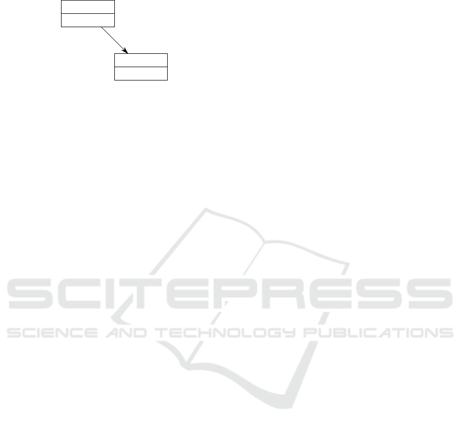
IFacade
FacadeBean
IBusiness
BusinessBean
doSomething()
Fig.1. The concept of session beans and dependencies: At the left hand the conceptional view
on two dependent beans, at the right hand the implementation of one bean in the program code
containing necessary design information as annotations.
[9] and also in the compiled Java bytecode. The design information is thus accessible
with standardized programming interfaces.
2.2 Business Logic Components
Business logic in JEE applications follows the inversion of control principle. Single
units are a certain kind of EJBs called session beans. They have an implementation (the
class) and an interface which can be simply the programming interface of the class, a
separate Java interface publishing selected methods, or a web service interface provided
by the server. By this means session beans define certain functionality of business logic
that can be executed. However, they don’t control actual execution. Instead, the server
is responsible for receiving requests, instantiating the session bean they are targeted to,
and forwarding related data.
This influences dependencies between session beans, which are specified descrip-
tively. This is done with a class attribute annotated with meta data. The dependencies
are then instantiated automatically too. All session beans are defined with meta data to
be valid for single requests, user sessions managed by the server, or the life time of the
whole application so that only a single instance exists. Thus a session bean or a net-
work of dependent session beans is instantiated by the server according to the lifecycle
definitions to serve single requests.
An example is shown in figure 1 with two dependent session beans. The Facade-
Bean has an interface IFacade published remotely as indicated with the annotation
@Remote. It contains a dependency to a session bean with the interface IBusiness
as specified by the annotation @EJB. The variable dependency is injected by the
server with an appropriate implementation of the interface IBusiness. With these
simple meta data annotations the network of session beans is defined so that it can be
instrumented by the server at run time.
2.3 Composition of Applications
Session beans are a vital part of JEE applications since they provide the actual busi-
ness logic. Therefore they are connected to other parts of the JEE environment. This
is always the case for session bean interfaces that can be used at least from inside the
32
CustomerServiceBean
CustomerService
[Local Interface]
CustomerService
[Web Service]
ICustomerService
ValidationBeanPersistenceBean
Interface
Layer
Business
Logic
Layer
Data
Layer
Web
Layer
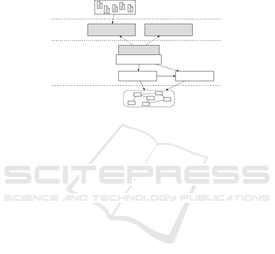
Fig.2. The structural view on the model with layers for web applications, published interfaces,
business logic, and data models. The core of the model is the business logic which is connected
to the other layers.
server, for example from web applications on the same server instance. When inter-
faces are published they are handled by respective communication layers provided by
the server. By this means remote access to the beans is possible, with different protocols
being handled by the server.
Business logic of enterprise applications is almost every time related to data stored
in databases. For this reason the JEE offers a persistence layer [10] that maps object-
oriented data to databases. This is also mostly configured with annotations. The related
entity beans are classes carrying information about the underlying relational schema,
including information about relations between entities. Single attributes and methods
can be decorated with validation information [6] restricting the value range of variables.
Both entails that rich information is available about the data model and its possible
state spaces. The mapping to an actual data base instance is configured in a separate
deployment descriptor.
In summary, business logic in the JEE is described with respect to the provided
program code fragments and its connections to the data in use as well as provided in-
terfaces. Applications consist of different modules for web applications, business logic,
and persistent data models. These modules can be merged into packages that contain
deployment descriptors for the modules and are interpreted by the servers to start the
enterprise applications.
3 Approach
We have so far outlined the design information that is embedded in program code and
configuration files of JEE applications. Based on this we will now propose a basic
domain-specific model that uses this information systematically.
33

3.1 Objectives
Our approach has the goal to apply the advantages of MDSD to Java enterprise ap-
plications. Selic defines the following to be the “quality of models” [11]: Abstraction
hides implementation details and thus allows to cope with complexity; understandabil-
ity finds representations that can be understood intuitively and thus with less effort;
accuracy ensures that models represent a real-world system realistically; predictiveness
allows to infer properties from a modeled system that are of interest, but not obvious,
by formal analysis or experiments; finally, inexpensiveness is desirable since a system
can be better analyzed and constructed when it is based on a model. We will use these
desirable properties of models as objectives for creation (and, later on, as criteria for
evaluation) of our model.
3.2 Structural View
A visual view on the structural elements of the model is illustrated in figure 2. The
model is structured into four layers: The business logic layer contains actual business
logic as session beans and the definition of interfaces at the level of the programming
language. The interface layer is inferred from the business logic layer and represents
resulting interfaces of session beans explicitly. The web layer is part of the model since
web applications can be part of enterprise application compositions. Although they are
not in the focus of our model, their interaction with session beans is comprehensible.
The data layer contains data models with entity beans. Although we will not focus on
data modeling here, we can use some of its properties to determine the state spaces the
business logic is using.
Figure 2 contains a simple example with three session beans: The CustomerSer-
viceBean has an interface ICustomerService published as a local interface and
available inside the server instance. In this case it is used by a web application running
on the same server. In addition, the interface is published as a web service accessible
by clients over the network. The bean has dependencies to the PersistenceBean
and the ValidationBean. Both have no separate interfaces and can thus only be
accessed from inside the business logic. Both use a data model consisting of a set of
entity beans.
In general, the structural view contains single units of program code for session
beans, interfaces, and definitions of dependencies which can be used in session bean
implementations to invoke methods of other session beans.
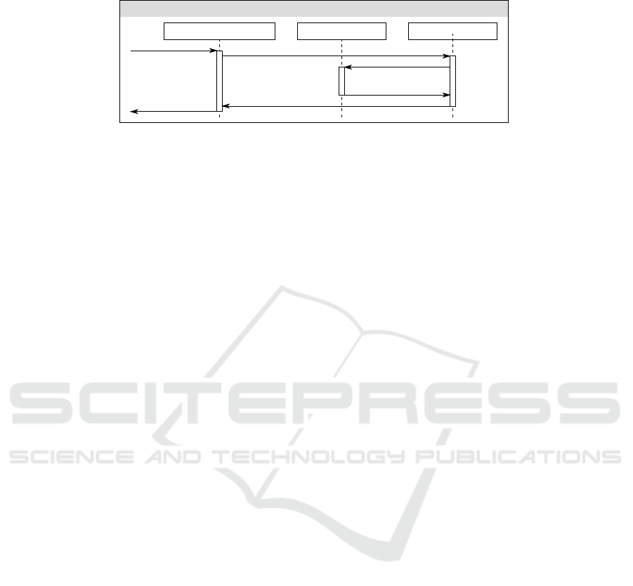
3.3 Behavioral View
Besides the structural view, behavioral aspects are represented in the model since re-
lated information is available in dependencies and method invocations between session
beans. Thus a request from a client arrives at an interface and results in a sequence of
method invocations. Possible sequences are determined by paths defined by the depen-
dencies which can be visualized similar to UML sequence diagrams [12] as illustrated
in figure 3. In this example, a request to the method createCustomerin the web ser-
vice interface is handled by the interface implementation in the CustomerService-
Bean and afterwards in the PersistenceBean and ValidationBean. Method
34
CustomerServiceBean
CustomerService [Web Service]
ValidationBean PersistenceBean
createCustomer
saveCustomer
void
true
validateCustomer
true
Fig.3. The behavioral view on the domain-specific model. It contains sequences of method invo-
cations that occur when a request arrives at the provided interfaces.
invocations are identified by method names and, in the case of parameter overloading,
by the parameter types (not shown here for clarity of the illustration). Methods can re-
turn values or the placeholder void. Of course, similar to UML sequence diagrams,
method invocations might occur only under certain conditions, which could also be
supplemented in the diagram.
3.4 Model Definition
Considered at an abstract level, the interface layer and the business logic layer thus con-
sist of nodes, i.e. session beans and interfaces, and edges, i.e. dependencies, which are
used by method calls from one session bean to another. The interfaces thus provide en-
try points to the model, and invocations of these interfaces lead to sequences of method
invocations in the session bean implementations.
We thus define a domain-specific model for JEE applications to be a tuple M =
hE, I, B, D, S, Ci. E is a set of entry points, each defined in an interface i ∈ I. B is a
set of business logic units that are connected by the set of dependencies D ⊆ B × B.
E and D imply that, beginning with the entry points, a set of possible sequences S of
method invocations exists. A subset S
U sed
⊆ S is realized as determined by method
invocations between session beans. Each sequence s ∈ S is not always strictly linear,
but has a set P
s
of possible paths that can be taken. P
s
defines more than one path if
conditions of the set C apply during method invocation that influence the specific path
a sequence takes.
This definition is comparatively simple, but covers the specifications of the JEE
business logic on an abstract level. It can be used to describe the structural as well as the
behavioral view on the model, and is the foundation of our proposal for the application
of MDSD techniques to JEE applications.
4 Value of the Model
The definition of the model as given above is no value in itself, but must be benefi-
cial during development of enterprise applications according to the objectives given in
section 3.1 during different stages of the development process.
At design time visual design of structural elements is possible, i.e. for session beans,
interfaces, methods, and dependencies. When source code is written, the behavioral
35

view can be extracted to analyze paths of method invocations. Both views thus sup-
port the design of enterprise applications and at the same time understandability and
program comprehension. In addition, program code can participate in model-to-model-
transformations: When abstract models are used for requirement definition, design, or
specification of applications, appropriate transformations to our model can be created.
Thus source code stubs of structural elements can be generated or differences can be
detected. More important, design information in the source code can be extracted and
transformed to abstract models if the transformation is bidirectional. The implementa-
tion of the enterprise application is supported since the visual design is tightly coupled
with creation and modification of the source code. In addition, the implementation is
structured by graphical representations of source code artifacts. The advantages regard-
ing program comprehension and understandability apply here, too.
Several ways exist to use the model for verification since abstract specifications
are connected to implementations directly. The model can be verified in structural and
behavioral views, and inconsistencies between model elements can be discovered. On
the implementation level static source code analysis can be applied since sequences and
paths allow to reduce complexity with slicing [13]. By this means a possible impact
of changes and resulting side effects can be detected at the level of the model. For
sequences, assertions can be given so that model checking for the Java code [14] is
possible. The state space is reduced for this purpose by considering only a limited set
of variables in related methods. When entity beans are used, the state space is further
reduced since value ranges and relations are limited. When source code is connected to
the entry points, static analysis can be applied to analyse if the interface contracts are
fulfilled by clients. In general, single elements of the model can be systematically used
for annotation with constraints, for example with the Java Markup Language [15].
At run time design information is also available to a certain degree as explained in
section 2.1 and can be used for debugging and monitoring. Graphical model representa-
tions can be reconstructed by means of reflection or bytecode analysis and thus support
detection of errors, especially when they visualize method invocations. When contracts
have been specified at model elements for verification, they can also be monitored at
run time to discover deviations.
Finally, when existing systems are abandoned, successional systems often re-use
existing processes or data to fulfill the same purposes. This is usually difficult since
models are mostly used as documentation, and as such have the tendency to get out of
sync with the running systems when adaption, maintenance, and tuning activities have
been applied for years. Since our model can be reconstructed from source code and
partly even from compiled program code, design recovery is possible by considering
the static elements of JEE applications.
In summary, the domain-specific model as proposed here can support development
and maintenance of JEE applications by different means in different stages of the de-
velopment process.
36

5 Evaluation
We will now evaluate the approach by considering its fulfillment of the objectives de-
fined in section 3.1.
The model certainly enables abstraction for JEE applications. It is based on in-
formation available in the program code, but extracts structures that are more coarse-
grained and simplified. This is true for the structural view, which is reduced to in-
terfaces, business logic classes, and dependencies, and also for the behavioral view,
which considers paths through the application. Design information in the program code
is therefore systematically used to enable working at different abstraction levels. For
the same reason, the model facilitates understandability since the abstraction can be
used to create visual representations as boxes-and-arrows-diagrams which are easily
understandable. This is especially true in comparison to the “traditional” enterprise
application development, which consists of manual creation of compilation units and
distributed creation and adaption of meta data fragments in program code.
The model can also contribute to accuracy: With model-to-model transformations
and visual representations, the implementation of enterprise applications is more sys-
tematic and can be partly automated. Usage of the model for verification as proposed in
section 4 enables predictiveness, since appropriate tools can infer properties of model
and implementation at different abstraction levels.
When such tools as described here are available for different development tasks,
the development of enterprise applications can be less expensive: Model-to-model-
transformations can be used to generate substantial structural parts of the source code.
Visual design tools allow for faster creation of the structures, and can also shorten the
time needed for program comprehension. The verification mechanisms can help to pre-
vent some classes of errors, and integration in debugging tools can fasten the detection
of errors that occur at run time.
In summary, we think that such models support the objectives and therefore fulfill
the requirements. However, this is so far only a proposal, so that no implementation and
no empirical evaluation exist. In addition, the model definition is so far limited to the
business logic and does not cover all JEE specifications.
6 Related Work
As mentioned in the introduction, most MDSD approaches consider source code a re-
sult of automated derivation from high-level notations. This leads to problems when
requirements, programming interfaces, libraries, or integration into existing or cus-
tomized source code are not supported by modeling tools. In contrast, we consider
models that already exist as design information in JEE applications. Thus we do not
need round-trip engineering [16] between notations since the program code contains all
necessary abstraction levels.
For the same reason we do not propose domain-specific languages (DSL) [17] with
separate notations. Model execution [18] is not applicable since the execution of JEE
applications is completely controlled by the application server. The models proposed
here are also not derived from abstract models and embedded in the program code [19],
but use only semantics of the JEE framework that are already available.
37

Since our approach relies on well-known program code structures, neither design
recovery[20] nor pattern detection [21] are applicable since they aim at detecting design
information that is not known beforehand and thus work with fuzzy data. For the same
reason tool support for program comprehension of arbitrary program code [22] is not
necessary.
7 Conclusions
We proposed a domain-specific model for JEE enterprise applications. This model does
not rely on any specific notation, but considers design information that is available in
program code of JEE applications, which are based on attribute-oriented programming
with the respective meta data. This enables working at different abstraction levels, in
which we see the potential for appropriate design, verification, debugging, and design
recovery tools.
The approachhas been evaluated theoretically with respect to desirable propertiesof
models: Abstraction, understandability, accuracy, predictiveness, and inexpensiveness.
These are from our point of view given since appropriate tools can enable program
comprehension, accurate implementation of requirements, verification of the related
program code, and reduction of effort for these tasks. However, the tools are still to
be developed to verify these assumptions. In addition, the model specification is not
complete, since only the most important aspects of the business logic are covered.
For the future we thus plan implementations of tools to demonstrate the feasibility
of the approach. For this purpose a bachelor’s thesis is currently written at our work-
ing group that implements, as a first step, the visualization of design information as
extracted from the program code. We will also consider the coverage of different JEE
specifications and for thus purpose define the model more precisely. In summary, we
are convinced that the approach to consider design information in enterprise applica-
tion frameworks is promising and want to stimulate discussion about its potential.
References
1. Fayad, M., Schmidt, D.C.: Object-Oriented Application Frameworks. Communications of
the ACM 40 (1997) 32–38
2. Brown, A.W., Iyengar, S., Johnston, S.: A Rational approach to model-driven development.
IBM Systems Journal 45 (2006) 463–480
3. Hailpern, B., Tarr, P.: Model-driven development: The good, the bad, and the ugly. IBM
Systems Journal 45 (2006) 451–461
4. Baker, P., Loh, S., Weil, F.: Model-Driven Engineering in a Large Industrial Context – Mo-
torola Case Study. In Briand, L., Williams, C., eds.: Model Driven Engineering Languages
and Systems, 8th International Conference, MoDELS 2005, Montego Bay, Jamaica, October
2-7, 2005, Proceedings. Volume 3713 of LNCS., Springer (2005) 476–491
5. Fowler, M.: PlatformIndependentMalapropism (2003) http://www.martinfowler.com/bliki/
PlatformIndependentMalapropism.html.
6. Sun Microsystems, Inc.: Introduction to the Java EE 6 Platform. White Paper (2009)
7. Schwarz, D.: Peeking Inside the Box: Attribute-Oriented Programming with Java 1.5. ON-
Java.com (2004) http://www.onjava.com/pub/a/onjava/2004/06/30/insidebox1.html.
38

8. Sun Microsystems, Inc.: JSR 318: Enterprise JavaBeans
TM
3.1 - Proposed Final Draft (2008)
http://jcp.org/en/jsr/detail?id=318.
9. Demers, F.N., Malenfant, J.: Reflection in logic, functional and object-oriented program-
ming: a short comparative study. In: In IJCAI ’95 Workshop on Reflection and Metalevel
Architectures and their Applications in AI. (1995) 29–38
10. Sun Microsystems, Inc.: JSR 220: Enterprise JavaBeans
TM
, Version 3.0 - Java Persistence
API (2006) http://jcp.org/en/jsr/detail?id=220.
11. Selic, B.: The Pragmatics of Model-Driven Development. IEEE Software 20 (2003) 19–25
12. Raistrick, C., Francis, P., Wright, J.: Model Driven Architecture with Executable UML.
Cambridge University Press, New York, NY, USA (2004)
13. Weiser, M.: Program Slicing. In: ICSE ’81: Proceedings of the 5th International Conference
on Software Engineering, Piscataway, NJ, USA, IEEE Press (1981) 439–449
14. Visser, W., Havelund, K., Brat, G., Park, S., Lerda, F.: Model Checking Programs. Auto-
mated Software Engineering Journal 10 (2003)
15. Beckert, B., Hhnle, R., Schmitt, P.H.: Verification of Object-Oriented Software. The KeY
Approach. Springer-Verlag New York, Inc. (2007)
16. Sendall, S., Kster, J.: Taming Model Round-Trip Engineering. In: Proceedings of Workshop
on Best Practices for Model-Driven Software Development. (2004)
17. van Deursen, A., Klint, P., Visser, J.: Domain-Specific Languages: An Annotated Bibliogra-
phy. ACM SIGPLAN Notices 35 (2000) 26–36
18. Hen-Tov, A., Lorenz, D.H., Schachter, L.: ModelTalk: A Framework for Developing Domain
Specific Executable Models. In: Proceedings of the 8th OOPSLA Workshop on Domain-
Specific Modeling. (2008)
19. Bravenboer, M., Visser, E.: Concrete Syntax for Objects: Domain-Specific Language Em-
bedding and Assimilation without Restrictions. In: OOPSLA ’04: Proceedings of the 19th
annual ACM SIGPLAN conference on Object-oriented programming, systems, languages,
and applications, New York, NY, USA, ACM (2004) 365–383
20. Kraemer, C., Prechelt, L.: Design recovery by automated search for structural design patterns
in object-oriented software. In: Proceedings. 3rd Working Conference on Reverse Engineer-
ing, Monterey, CA 1996. Los Alamitos, Calif. (1996) 208–215
21. Philippow, I., Streitferdt, D., Riebisch, M., Naumann, S.: An approach for reverse engineer-
ing of design patterns. Software and Systems Modeling 4 (2005) 55–70
22. Schauer, R., Keller, R.K.: Pattern Visualization for Software Comprehension. In: IWPC ’98:
Proceedings of the 6th International Workshop on Program Comprehension, Washington,
DC, USA, IEEE Computer Society (1998) 4
39
