
USING AToM
3
FOR THE VERIFICATION OF WORKFLOW
APPLICATIONS
Leila Jemni Ben Ayed, Ahlem Ben Younes and Amin Ben Brahim Achouri
Research Unit of Technologies of Information and Communication (UTIC), ESSTT
5, Avenue Taha Hussein, P.B. 56, Bab Menara, 1008 Tunis, Tunisia
Keywords:
Workflow applications, Specification, AToM
3
, UML activity diagram, Formal verification, Event B.
Abstract:
In this paper, we propose an approach for the verification of workflow applications using AToM
3
and Event
B. Workflow carries applications where many actors take part and cooperate in order to execute operations.
Upon composing those operations, many problems such as deadlock, freeness and livelock might appear. In
this context, we are going to show how to build a meta-model for UML activity diagram in AToM
3
. From this
meta-model, AToM
3
generates a visual tool to build and to specify workflow applications where syntactical
verification is made. Further, we are going to define a graph grammar to generate a textual code from the
graphically specified workflow. This code will maintain information about all the activities and their depen-
dencies. Another role of the graph grammar is to generate an Event B machine used for the verification of the
workflow. Structural errors like deadlock and absence of synchronization can be captured from the resulted
Event B model. Functional requirements are also verified using the resulted Event B model.
1 INTRODUCTION
Workflow application consists on a composition of
many application components that should be executed
in a specific order depending on their control and data
dependencies (Espinosa et al., 2000). They are ex-
tensively used in scientific fields like meteorology,
bioinformatics, biology and astronomy (Foster and
Kesselman, 1998). This can cause a structural error
in the workflow. Deadlocks and lack of synchronisa-
tion are examples of those errors (Sumit et al., 2007).
It becomes an imperative to maintain the correctness
of the workflow applications from their conception to
their execution.
It is therefore necessary to follow a strict process
of modeling, and formal verification. This allows
one to rigorously verify required properties before the
implementation. The last few years have witnessed
the emergence of a number of successful specifica-
tions approaches which dealt with workflow applica-
tions(Sadiq and Orlowska, 1996)(Wang et al., 2008).
More precisely, activity diagrams are used to model
organisational process. Thus, a sequencing of a set
of activities which are defined to accomplish larger
and sophisticated goals. They are adequate to specify
workflow (Dumas and Hofstede, 2001) (Russell et al.,
2006).
On the other hand, workflow verification can be
composed of semantic, syntactic and structural verifi-
cation. Semantic verification means that the model is
in conformance with the business process goals. Syn-
tactic verification means that the model is in confor-
mance with the grammar of the language. Structural
verification means that the model will not lead to er-
roneous execution like deadlock and problem of syn-
chronization.
In our previous work (Ben Younes and Ben Ayed,
2008), we have proposed a specification and verifi-
cation approach using UML activity diagrams (UML
AD) to specify workflow applications and Event B
to prove the correctness of the workflow. A work-
flow application is initially specified with UML AD.
The resulting model is then transformed into event B
and required properties are added as invariants of this
model. The next step consists on the verification that
the model preserves properties using the tool B4free.
We considered syntactical and structural properties.
The generation of Event B model is based on a set of
translation rules and properties are added by the user.
In this paper, we propose an approach for the
verification of workflow applications using AToM
3
(De Lara and Vangheluwe, 2002a). This allow an au-
tomatic verification of syntactical and structural prop-
erties. AToM
3
supports model transformation using
32
Jemni Ben Ayed L., Ben Younes A. and Ben Brahim Achouri A. (2010).
USING AToM3 FOR THE VERIFICATION OF WORKFLOW APPLICATIONS.
In Proceedings of the 5th International Conference on Software and Data Technologies, pages 32-39
DOI: 10.5220/0002930400320039
Copyright
c
SciTePress

graph grammar. In AToM
3
, formalisms and models
are described as graphs. From the specification of
a formalism (i.e., graph), AToM
3
produces a tool to
operate visually (create and edit) models described
in the formalism indicated. With AToM
3
, meta-
modelling becomes easier, since the graphical inter-
face provided to specify any formalism. Using Entity
relationship formalism or UML class diagram, users
can create their own formalism. Besides, depending
on the graph grammar, this tool can transform graphi-
cal model in a specified formalism into another equiv-
alent model expressed in a different formalism such as
textual one (De Lara and Vangheluwe, 2002b) (Raida
El Mansouri and Chaoui, 2008).
This contribution aims at first to obtain a visual
tool to model workflow applications in activity dia-
gram formalism using meta-modelling. And to auto-
mate the transformation of this model into a textual
code, using graph grammar. The graph grammar will
map the model created to form a well structured Event
B machine ready to be proved with B4free. Struc-
tural properties are verified based on graph grammar.
When there is added properties, which are not related
to activities diagrams but to user requirements, the
event B model can be used.
Using this solution, syntactical properties are ver-
ified with AToM
3
and structural and semantics prop-
erties are verified with Event B. This allows to avoid
generated errors, due to syntactical errors, in the re-
sulting Event B model. Then, only structural and se-
mantic properties are considered. Also, the transfor-
mation of activity diagram into Event B preserves the
equivalence between the two models thanks to the use
of graph grammar, compared to our previous works,
where we should to prove the correctness of transfor-
mation rules.
The paper before hands is organized as follows:
in section 2 we present meta-modelling in AToM
3
. In
section 3, we define graph grammar in AToM
3
. Sec-
tion 4 as such highlights how to specify activity di-
agram and generate a visual tool for this formalism.
Section 5 is devoted to propose a graph grammar so
as to generate a textual code and Event B machine
from the model of workflow. In section6, we propose
an algorithm for the detection of structural errors in
workflow applications. In order to validate our ap-
proach, we expose an case study of workflow appli-
cation. Finally , the last section concludes our work.
2 META MODELLING
A meta-model is the process of modelling a syn-
tax and a semantics of a formalism. Thus, a meta-
modelling tool allows a domain experts to build a
meta-model and synthesize a domain specific mod-
elling environment from it. In AToM
3
, the highest
meta-model level is the Entity Relationship model
and UML class diagram. Entity and rel (relation-
ship) are the two component of Entity Relationship
meta-meta-model. To make a meta-model modelled
with one of the two meta-meta-models used in AToM
3
more expressive and to give it some constraints de-
pending on its type, we should add other constraints
to the meta-model (formalism) using constraints lan-
guage. So no syntactical errors will be found in the fu-
ture models. For example, when we model the meta-
model of UML activity diagram, an activity generally
does not have more than one outgoing connection.
This constraint can not be expressed graphically, we
need to encode it in Python language. It is also pos-
sible in AToM
3
to encode a constraint using Object
Constraint Language OCL used in UML.
3 GRAPH GRAMMAR
The grammar of graph is made up of a rules of pro-
duction, each one of them contains a graph on the left
(LHS) and another on the right (RHS). After mapping
a LHS and a sub-graph of our model,when there is
an agreement between these two graphs, the rule can
be applied. As a result, this sub-graph is replaced by
the RHS of the rule. In AToM
3
, the model transfor-
mations are specified through a graph grammars, and
consist on an initial action, a final action and a trans-
formation rules. Each rule consists on a Left Hand
Side (LHS) and a Right Hand Side (RHS) graphs, a
Condition (pre condition), an Action (post condition)
and a Priority properties.
During the execution of a model transformation,
Graph Rewriting Processor (GRP) of AToM
3
iterates
through the list of the rules sorted by their prior-
ity in an ascending order (De Lara and Vangheluwe,
2002b). Then, it tries to apply the current rule to the
model. If the rule makes a match (LHS pattern is
found and conditions are met), it is executed and the
GRP repeats trying each rule again from the begin-
ning of the list. This continues until there are no more
rules that can be applied. And then the GRP notify
that the model transformation is completed.
So a model transformation such as a code gener-
ation, a simulators and a graph reduction which are a
graph grammar based, can be created in AToM
3
. An
important aspect in a model transformation is the au-
tomatic generation of the target model, obtained by
the transformation, thanks to the graph grammar.
USING AToM3 FOR THE VERIFICATION OF WORKFLOW APPLICATIONS
33
4 META MODELLING UML
ACTIVITY DIAGRAMS
Using the Entity Relationship, meta-formalism, as de-
fined in AToM
3
, we can specify an activity diagram.
First, we consider it at an abstract level. And, we
focus on how an activity diagram models are mod-
elled at a conceptual level. In an activity diagram, an
activity should have a type which may be exchange-
able by an initial, a final or a simple activity and a
name as well. An activity is linked to another ac-
tivity, to a synchronization node or to a choice node.
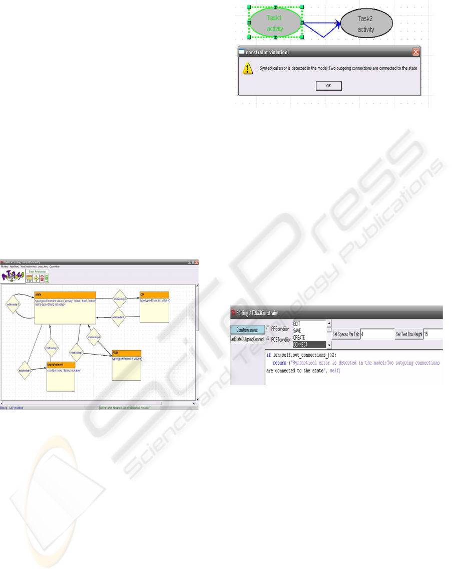
Based on those considerations and as it is shown in
figure 1, we have designed an Entity dropped from the
meta-formalism of the Entity Relationship with two
attributes (we can add more if needed). This Entity
named state is respectively linked to the Entity syn-
chronization (AND), to the Entity choice (OR) and to
the Entity branchement. The Entity OR and the Entity
AND have an attribute type which value can be split
or join.
Figure 1: Meta-model of UML Activity diagrams.
After creating this model with AToM
3
, some con-
straints should be added as it is shown in figure 3. The
use of such constraint will verify the conformanceof a
workflow model with UML activity diagram. Hence,
Syntactical errors will be forbidden in our formalism.
In fact, when we build a workflow model using our
formalism, errors like having a model that contain a
Activity node with more than one outgoing connec-
tions will be denied. So, a message containing this
error will be reported to the users and the creation of
such errors will be stopped (figure 2).
We have the choice to encode those constraints
in OCL or in Python scripts. As examples of those
constraints, a state Entity does not have more than
one incoming connection and more than one outgoing
connection. A state that is an Initial activity does not
have any incoming connection. A State that is a final
Figure 2: The detection of Syntactical errors.
activity does not have any outgoing connection. Also
AND split node does not havemore than two outgoing
connections and more than one incoming connection
and so on. As AToM
3
is able to generate the activity
diagram formalism, a tool to specify any workflow
models in the formalism of UML activity diagram is
created.
In our approach, we consider that the node AND
split (also an OR split) does not have more than two
outgoing connections. For that, an AND split node
having more than two outgoing connections can be
created simply through composing the first one more
than twice. The same thing with an OR join and an
AND join.
Figure 3: Editing constraint in AToM
3
.
5 MODEL TRANSFORMATION:
OUR GRAPH GRAMMAR
In this section, we will cast our graph grammar able
to transform a graphical workflow models to a textual
code and to an Event B machine. The purpose behind
this automatic transformation is to prove the correct-
ness of a workflow. An Activity diagram model will
be mapped into a file that contains all activities names
and the dependencies between them and also another
Event B machine file. This graph grammar is shown
in table 1.
This graph grammar contains a six rules proceed-
ing with an Initial action that opens the two files and
gives to all model nodes an attribute named visited.
Each rule of our graph grammar contains a graph in
the LHS and another in the RHS. All nodes on both
ICSOFT 2010 - 5th International Conference on Software and Data Technologies
34
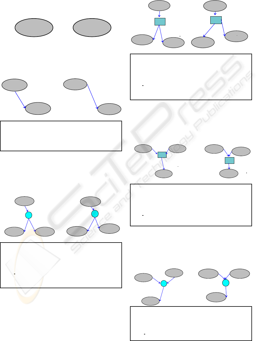
Table 1: A graph grammar to generate textual code and Event B machine.
Rule 1: Generates an initial activity and the head of the
Event B machine with the name of workflow model. Priority
1.Condition:node(1).visited==0 Action:node(1).visited=1
initial
<ANY>
1
::
<COPIED>
<COPIED>
1
Rule 2: Generates an activities connected sequen-
tially and an Event B machine structurally orga-
nized from this sequential execution of the activ-
ities. Priority 2. Condition:node(2).visited==0
Action:node(1).visited=1 and node(2).visited=1
<ANY>
<ANY>
<ANY>
<ANY>
3
1
2
::
<COPIED>
<COPIED>
<COPIED>
<COPIED>
3
1
2
VARIABLES stateNi
INVARIANT stateNi:{node(1).name, node(2).name}
ASSERTIONS (stateNi=node(1).name & G0node(2).name)
INITIALISATION stateNi:=node(1).name
EVENTS
Eventseq=SELECT stateNi=node(1).name & G0node(2).name THEN stateNi:=node(2).name k
S0node(2).name END END
<ANY>
<ANY>
activity
<ANY>
activity
<ANY>
SPLIT
OR
6
7
5
1
3
4
2
::
<COPIED>
<COPIED>
<COPIED>
<COPIED>
<COPIED>
<COPIED>
<COPIED>
OR
6
7
5
1
3
4
2
VARIABLES stateN(i+1)B1, stateN(i+1)B2
INVARIANT stateN(i+1)B1:{node(1).name, node(3).name} & stateN(i+1)B2: {node(1).name,
node(4).name}
ASSERTIONS (stateN(i+1)B1=node(1).name & G0node(3).name & condition(node(1).name)) or
(stateN(i+1)B1= node(1).name & G0node(4).name & not(condition(node(1).name)))
INITIALISATION stateN(i+1)B1:=node(1).name k stateN(i+1)B2:=node(1).name
EVENTS
Eventor split=IF stateN(i+1)B1=node(1).name & G0node(3).name & condition(node(1).name)
THEN stateN(i+1)B1:=node(3).name k S0node(3).name ELSIF stateN(i+1)B2=node(1).name
& G0node(4).name & not(condition(node(1).name)) THEN stateN(i+1)B2:=node(4).name k
S0node(4).name END END
Rule 5: Generates an activities connected with an
OR join and an Event machine B structurally or-
ganized from the OR join execution of the activ-
ities. Priority 6. Condition: node(3).visited==0
Action: node(1).visited=1 and node(2).visited=1
and node(3).visited=1 and node(4).visited=1.
activity
<ANY>
activity
<ANY>
<ANY>
<ANY>
JOIN
OR
7
5 6
1 2
4
3
::
<COPIED>
<COPIED>
<COPIED>
<COPIED>
<COPIED>
<COPIED>
<COPIED>
OR
7
5
6
1
2
4
3
VARIABLES stateN(i+1)B1, stateN(i+1)B2
INVARIANT stateN(i+1)B1:{node(1).name, node(4).name} & stateN(i+1)B2:{node(2).name,
node(4).name}
ASSERTIONS (stateN(i+1)B1=node(1).name & G0node(4).name) or (stateN(i+1)B2=node(2).name
& G0node (4).name)
INITIALISATION stateN(i+1)B1:=node(1).name or stateN(i+1)B2:=node(2).name)
EVENTS
Eventor join=IF G0node(4).name & stateN(i+1)B1=node(1).name THEN S0node(4).name k
stateN(i+1)B1:=node(4).name ELSIF G0node(4).name & stateN(i+1)B2=node(2).name THEN
S0node(4).name k stateN(i+1)B2:=node(4).name END END
Rule 3: Generate an activities connected with an
AND split and an Event machine B structurally or-
ganized from the AND split execution of the ac-
tivities. Priority 3. Condition:node(2).visited==0
Action:node(1).visited=1 and node(2).visited=1
and node(3).visited=1 and node(4).visited=1
SPLIT
AND
<ANY>
<ANY>
activity
<ANY>
activity
<ANY>
2
6
7
5
1
3 4
::
SPLIT
AND
<COPIED>
<COPIED>
<COPIED>
<COPIED>
<COPIED>
<COPIED>
2
6
7
5
1
3
4
VARIABLES stateN(i+1)B1, stateN(i+1)B2
INVARIANT stateN(i+1)B1 :{node(1).name, node(3).name} & stateN(i+1)B2:{node(1).name,
node(4).name}
ASSERTIONS(stateN(i+1)B1=node(1).name & G0node(3).name) or (stateN(i+1)B2=node(1).name
& G0node(4).name)
INITIALISATION stateN(i+1)B1:=node(1).name k stateN(i+1)B2:=node(1).name
EVENTS
Eventand split=IF G0node(3).name & stateN(i+1)B1=node(1).name THEN
stateN(i+1)B1:=node(3).name k S0node(3).name ELSIF G0node(4).name &
stateN(i+1)B2=node(1).name THEN stateN(i+1)B2:=node(4).name k S0node(4).name END
END
Rule 4: Generates an activities connected to an
OR split and an Event machine B structurally or-
ganized from the OR split execution of the activ-
ities. Priority 5. Condition: node(2).visited==0
Action: node(1).visited=1and node(2).visited=1 and
node(3).visited=1 and node(4).visited=1
Rule 6: Generates an activities connected with an AND join
and an Event machine B structurally organized from this
AND join execution of the activities. Priority 4. Condition:
node (2).visited==0 Action: node (1).visited=1 and node
(2).visited=1 and node (3).visited=1 and node (4).visited=1
JOIN
AND
activity
<ANY>
activity
<ANY>
<ANY>
<ANY>
3
7
5
6
1
2
4
::
<COPIED>
AND
<COPIED>
<COPIED>
<COPIED>
<COPIED>
<COPIED>
<COPIED>
3
7
5
6
1 2
4
VARIABLES stateN(i+1)B1, stateN(i+1)B2
INVARIANT stateN(i+1)B1:{node(1).name, node(4).name} & stateN(i+1)B2:{node(2).name,
node(4).name}
ASSERTIONS (stateN(i+1)B1=node(1).name & stateN(i+1)B2=node(2).name & G0node(4).name)
INITIALISATION stateN(i+1)B1:=node(1).name k stateN(i+1)B2:=node(2).name
EVENTS
Eventand join=IF stateN(i+1)B1=node(1).name & stateN(i+1)B2=node(2).name & G0node(4).name
THEN stateN(i+1)B1:=node(4).name k stateN(i+1)B2:=node(4).name k S0node(4).name END END
USING AToM3 FOR THE VERIFICATION OF WORKFLOW APPLICATIONS
35

LHS and RHS are labelled with a number. This
number is used during the execution of the transfor-
mation. Each rule has a condition and an action con-
straint. Here in our grammar node(1).visited means
attribute visited of the node labelled with the number
1. G0x is the guard of the activity with the name x.
S0x is the substitution that takes place when the event
is executed on the activity with the name x.
Each workflow pattern is transformed into an
Event B machine which contain one Event. To pre-
serve the semantic of UML activity diagram via an
Event B machine, we use a tokens in all obtained
Event B machine that express the state during the ex-
ecution of the workflow. StateNi is the token used in
rule2. StateN(i+1)B1, StateN(i+1)B2 are the tokens
used in rule 3, 4, 5 and 6. The tokens values are the
name of the activities. The variable ’i’ is a counter
that it is initialized to 1 after the initial activity and af-
ter an OR split node or AND split node it is increased
with 1 and after an OR join node or AND join node
it is decreased with 1. Each Event, corresponding of
each workflow pattern, will be fired if its guard is true
and the token is affected to it’s initial value.
As a Final action of the graph grammar mentioned
above, we erase the temporal attribute visited from all
model nodes and we close the two initially created
files. So, the obtained Event B machine can be at-
tainable through combining all the obtained machines
applying the six rules. Thus, one consistent Event B
machine will be obtained.
6 WORKFLOW WITH
STRUCTURAL ERRORS
Deadlock and absence of synchronization are exam-
ples of the structural errors that can be found in a
workflow models (Wang et al., 2008). A deadlock
occurs in a workflow model, if an OR split node is
complemented with an AND join node. As for the
problem of synchronization, it occurs when an AND
split node is complemented with an OR split node. To
detect such errors, we can apply an algorithm which is
explained in this current section. However, its worth
noticing that before applying the algorithm, a prelim-
inary test can be applied to the model. We count the
numbers of the AND split, AND join, OR split and
OR join which are presented in the model. If the num-
ber of the AND split is equal to the number of the
AND join and the number of the OR split is equal to
the number of the OR join, then, we pass to the execu-
tion of the algorithm. Else, if the number of the AND
split is superior to the number of the AND join, and
the number of the OR split is inferior to the number of
the OR join, we conclude that one or more problems
of synchronization is found in the model. Else if the
number of the AND split is inferior to the number of
the AND join, and the number of the OR split is supe-
rior to the number of the OR join, then, a deadlock is
found in our model. In the second case the number of
errors (absence of synchronization) presented in the
model can be determined by withdrawing the number
of the AND join from the number of the AND split.
In our approach, after verifying the workflow, a report
containing the type of errors and their location exactly
in the model will be reported to the user.
When we apply the algorithm, we can localize
where the errors are detected exactly. The algorithm
will operate on the obtained file that contains all activ-
ities names and the inter dependencies between them.
Algorithm 1: ALGORITHM H
1
.
Data: Subject file.
Result: Type of errors, Location
begin
while (exist (AND join)) do
Incoming activities (A, B, AND join)
t: =0,Prev(A):=A,Prev(B): =B
Verif future (Prev(A))
Verif future (Prev(B))
while (Prev (A)! =InitialTask or Prev
(B)! = InitialTask) do
if (exist
(Outgoing activities(Prev(A),
Prev(B), TYPE split)) then
Treatment
else
if (t=0) then
Seek(Prev(A))
t=1
else
Seek(Prev(B))
t=0
After dealing with the node AND join node the al-
gorithm will deal with the node OR join. We define
here the role of the functions used in the algorithm.
-exist (AND join): returns the line where an AND join
(respectively OR join node) is mentioned and 0 if not.
-depth (AND join): is calculated through withdrawing
the number of the OR join and the AND join from the
number of the AND split and the OR split occurred
from the initial activity to this AND join node.
-Incoming activities (A, B, AND join): modifies the
two parameters A and B with the names of the two
activities which are the incoming activities.
-Prev (A): the Previous of the activity A. If C and A
ICSOFT 2010 - 5th International Conference on Software and Data Technologies
36
are executed sequentially so Prev (A):=Prev (C)
-Verif future (Prev (A)): return 1 if the activity A
comes from the future, else 0
-Outgoing activities (Prev (A), Prev (B), TYPE)):
modifies the parameter TYPE with the name of the
split node which has A and B like an outgoing activ-
ities. It returns the line of the split, or 0 if it does not
exist.
-Seek (Prev (A)): returns the previous of A.
-Treatment: tests if the node TYPE split can generate
a structural errors and then fills the report file with the
necessary information.
7 CASE STUDY
To illustrate our approach, we give an example of
a workflow application. First, we try to model the
workflow using the formalism created with AToM
3
,
then, we apply the model transformation to the de-
sign. Suppose that we want to design a workflow ap-
plication that read three numbers a, b and c from dis-
persed workstations. Then, the application is scripted
into the following Mathematical equation (a-b)*c.
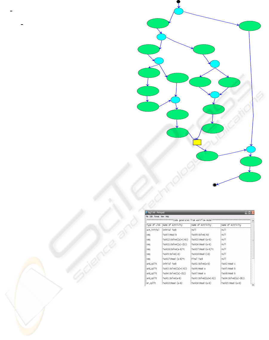
Applying the graph grammar listed above to our
model, two files will be created. In this section, we are
focus on the file which involves the activities names
and their dependencies. Then, applying the prelim-
inary test to the obtained file shown in figure 6, we
found that: Number(AND split)=4>Number(AND
join)=3. And number(OR split)=0<Number(OR
join)=1. Therefore, we conclude that one error of lack
of synchronization exists in our model.
To better explain the algorithm of section 6,
we use the file shown in figure 5, then, we apply
our algorithm. First, Prev(Task13)=Task13 and
Prev(Task14)=Task14. We cross the file in order to
seek for Task13. We found a sequential execution for
Task12 and Task13. So Prev(Task13)=Prev(Task12).
At a later stage, we verify if Task12 and Task14
are the results of a same join node, which is
false. So, we continue searching for Prev(Task13)
and Prev(14). For Task14, we found Task14
and Task11 are sequentially connected conse-
quently Prev(Task14)=Prev(Task11). Task11 and
Task12 are not the result of a join node. Task
11 is an activity created after a join node hav-
ing Task7 and Task 8 like incoming activities so
Prev(Task14)=Prev(Task11)=Prev(Task7,Task9).
Besides, Task7 and Task8 originate from an AND
join node having Task4 as incoming activity.
Checking if Task4 and Task12 are originate from
the same join node we have found out that this
was wrong, hence, we carry on our search. As
split
AND
Task1:Solve(a-b)
activity
Task2:Read c
activity
split
AND
Task3:Solve((a)+(-b))
activity
Task4:Solve((a)-(b))
activity
split
AND
Task5:Read b
activity
Task9:Solve(-b)
activity
Task10:Read(-b)
activity
split
AND
Task12:Solve((a)+(-b))
activity
Task13:Read(a-b)
activity
Task6:Read a
activity
split
AND
Task7:Read a
activity
Task8:Read b
activity
join
AND
Task11:Solve((a)-(b))
activity
Task14:Read(a-b)
activity
join
OR
Task15:Read(a-b)
activity
join
AND
Task16:Solve (a-b)*c
activity
Task17:Read (a-b)*c
action
Figure 4: Representation of the workflow specification us-
ing activity diagram formalism.
Figure 5: Resulted code from the graph transformation.
for Task12, Prev(Task12)=Prev(Task10,Task6)
and Prev(Task10)=Prev(Task9)=Prev(Task5) so
Prev(Task10,Task6)=Prev(Task5,Task6)=Prev(Task3).
Thus, we found that Task3 and Task4 resulted from
an AND split node. We can see that an AND join is
complemented with an OR join node. It is an error
of absence of synchronization. So, this message is
reported to the user and the location of this error will
be reported as well as shown in figure 6.
USING AToM3 FOR THE VERIFICATION OF WORKFLOW APPLICATIONS
37
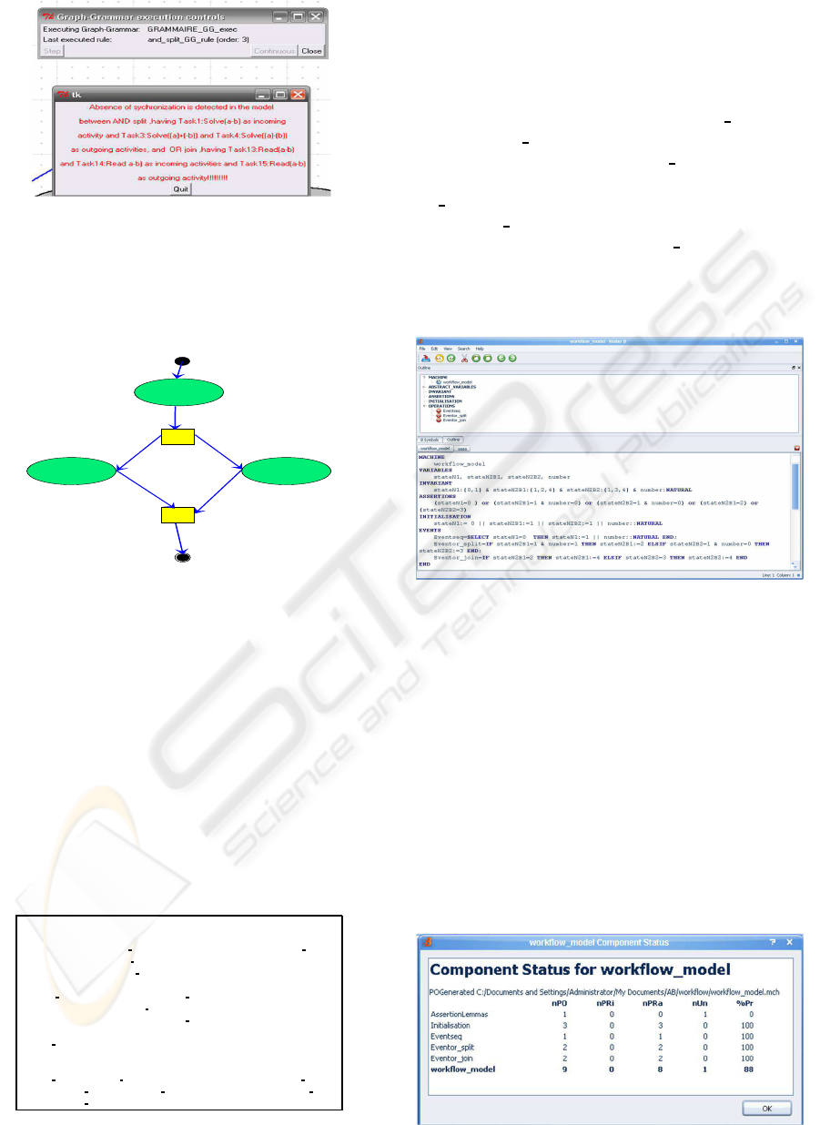
Figure 6: Reported message.
Now, we use another example of a workflow
model as shown in the figure 7. We will show, with
the use of this example, the importance of using Event
B in our approach.
split
OR
join
OR
Task1: Read number
activity
Task2: number=1
activity
Task3: number=0
activity
Figure 7: Workflow model.
This example illustrates a sequential execution of
an initial task and Task1, which allows to initialize
the variable number with any natural number chosen
arbitrary, and an OR split node, which depending of
the value of the variable number, it will conduct the
execution of the workflow to Task2 if number is equal
to one and to the Task3 if this number is equal to zero.
Then an OR join node is complemented with the OR
split. Applying our graph grammar to the example of
7, we obtain the Event B machine shown in figure 8
with three Event the first for the sequential execution,
the second for the OR join node execution and the
third for the OR split node execution.
MACHINE Workflow model
VARIABLES stateN1, stateN2B1, stateN2B2
INVARIANT stateN1:{Initial Task,Task1} & stateN2B1:{Task1, Task2, Final Task} &
stateN2B2:{Task1, Task3, Final Task}
ASSERTIONS (stateN1=Initial Task & G0Task1) or (stateN2B1=Task1 & G0Task2
& condition (Task1)) or (stateN2B2=Task1 & G0Task3 & not(condition (Task1))) or
(G0Final Task & stateN2B1=Task2) or (G0Final Task & stateN2B2=Task3)
INITIALISATION stateN1:=Initial Task k stateN2B1:=Task1 k stateN2B2:=Task1
EVENTS Eventseq=SELECT stateN1=Initial Task & G0Task1 THEN stateN1:=Task1 k
S0Task1 END;
Eventor split=IF stateN2B1=Task1& G0Task2 & condition (Task1) THENstateN2B1:=Task2
k S0Task2 ELSIF stateN2B2=Task1 & G0Task3 & not(condition(Task1)) THEN
stateN2B2:=Task3 k S0Task3 END;
Eventor join=IF G0Final Task & stateN2B1=Task2 THEN S0Final Task k
stateN2B1:=Final Task ELSIF G0Final Task & stateN2B2=Task3 THEN S0Final Task k
stateN2B2:=Final Task END END
Figure 8: Obtained Event B machine from graph transfor-
mation.
After obtaining this Event B machine, some trans-
formations should be made in the whole model.
Some of those transformation will be made automati-
cally and other manually by the the workflow mod-
eller. For automatic transformation, we transform
Taski for i from 1 to 3 with i and Initial Task with
zero and Final Task with 4. Transforming G0Task1,
G0Task2, G0Task3 and G0Final Task to the real
guard of respectively Task1, Task2,Task3 and Fi-
nal Task and substituting S0Task1, S0Task2, S0Task3
and S0Final Task with the real substitution of respec-
tively Task1, Task2,Task3 and Final Task. After mak-
ing those transformation, a well structured event B
model is obtained. we edit the resulted machine in
the tool Atelier B as shown in the figure 9
Figure 9: Workflow model.
This model, Event B machine, contains ASSER-
TIONS clauses and INVARIANT clauses. INVARI-
ANT clause describes the properties of the attributes
defined in the clause VARIABLES. The ASSERTION
clause states that one of the events guards is always
true. This means that there is no deadlock. If several
events can be fired at the same time, then one of them
will be selected in a non-deterministic way. If, in a
given state, no event may be fired, then the system is
blocked. We conclude that a deadlock occur. In addi-
tion, users can define other properties of the workflow
using Event B. Thus, the accordance with the business
process goals (workflow) can be verified.
Figure 10: Summary of proofs reported from Atelier B.
ICSOFT 2010 - 5th International Conference on Software and Data Technologies
38

8 CONCLUSIONS
In this paper, we discussed the advantages of using
meta-modelling and model transformation. AToM
3
,
the tool that implements these two concepts, is very
useful in automatic way.
The originality of the work under focus stems
from the fact that it casts light on two different waves
of research and takes benefit from both of them. In
doing so, first, it aims to obtain a visual tool to model
workflow applications in activity diagram formalism
using meta-modelling, in order, to ensure syntactical
verification. Then, to automate the transformation of
this model into a textual code, using graph grammar
to verify structural errors like deadlock and absence
of synchronization. The graph grammar will map the
model created to form a well structured Event B ma-
chine ready to be proved formally with B Method.
One has recourse to use Event B since the semantic
verification that we gain.
Indeed, we apply our algorithm to the gener-
ated file containing activities names and the inter-
dependencies. As a result, structural errors, like dead-
lock and absence of synchronization, can be captured
from the model. The file containing Event B machine
can be used formally, to find structural errors and to
verify the semantic of the workflow model.
The use of the variant B allows to automatically
generate Proofs of obligation and this is the motiva-
tion for the use of such formal method. In the case
of complex workflow applications, using the refine-
ment and the composition as defined in B method our
approach allows to specify and to verify the whole ap-
plication by decomposing it in sub modular.
REFERENCES
Ben Younes, A. and Ben Ayed, L. J. (2008). From UML
Activity Diagrams to Event B for the Specification
and the Verification of Workflow Applications. In
COMPSAC ’08: Proceedings of the 2008 32nd An-
nual IEEE International Computer Software and Ap-
plications Conference, pages 643–648, Washington,
DC, USA. IEEE Computer Society.
De Lara, J. and Vangheluwe, H. (2002a). Atom
3
: A Tool
for Multi-formalis and Meta-modelling. In FASE ’02:
Proceedings of the 5th International Conference on
Fundamental Approaches to Software Engineering,
pages 174–188, London, UK. Springer-Verlag.
De Lara, J. and Vangheluwe, H. (2002b). Using Meta-
Modelling and Graph Grammars to Process GPSS
Models. In Proceedings of the 16th European Sim-
ulation Multiconference on Modelling and Simulation
2002, pages 100–107. SCS Europe.
Dumas, M. and Hofstede, A. H. M. t. (2001). UML Activ-
ity Diagrams as a Workflow Specification Language.
In guillemotleftUML’ ’01: Proceedings of the 4th In-
ternational Conference on The Unified Modeling Lan-
guage, Modeling Languages, Concepts, and Tools,
pages 76–90, London, UK. Springer-Verlag.
Espinosa, J. M. M., Drira, K., and Diaz, M. (2000). Modle
de description de procdures Workflow bas sur la rcri-
ture de graphes. In Journes FAC’2000 Formalisation
des Activits Concurrentes.
Foster, I. and Kesselman, C. (1998). The Grid: Blueprint
for a Future Computing Infrastructure. Morgan Kauf-
mann Publishers.
Raida El Mansouri, E. K. and Chaoui, A. (2008). A graph-
ical environment for petri nets ina tool based on meta
modelling and graph grammars. In World Academy of
Science, Engineering and Technology 44.
Russell, N., van der Aalst, W. M. P., ter Hofstede, A. H. M.,
and Wohed, P. (2006). On the suitability of uml 2.0
activity diagrams for business process modelling. In
APCCM ’06: Proceedings of the 3rd Asia-Pacific con-
ference on Conceptual modelling, pages 95–104, Dar-
linghurst, Australia, Australia. Australian Computer
Society, Inc.
Sadiq, W. and Orlowska, M. E. (1996). Modelling and ver-
ification of workflow graphs. Technical report, Com-
puter Science Technical Report 386. Queensland.
Sumit, W. S., Sanjeev, K. A., Song, J., Koh, M., and See,
S. (2007). Modeling and Verifying Non-DAG Work-
flows for Computational Grids. In IEEE SCW, pages
237–243.
Wang, B., Zhang, S., and Xue, Q. (2008). The Analysis on
Grid Workflows Deadlock by Petri Nets. In Proceed-
ings of the 7th world Congress on Intelligent Control
and Automation.
USING AToM3 FOR THE VERIFICATION OF WORKFLOW APPLICATIONS
39
