
SMART VISION SENSOR FOR VELOCITY ESTIMATION USING A
MULTI-RESOLUTION ARCHITECTURE
Mickael Quelin, Abdesselam Bouzerdoum and Son Lam Phung
ICT Research Institute, University of Wollongong, Northfields Avenue, NSW 2522 Wollongong, Australia
Keywords:
Insect vision, Multi-resolution architecture, Elementary Motion Detector (EMD), Elementary Velocity Detec-
tor (EVD), Horridge template model, Reichardt correlator.
Abstract:
This paper presents a velocity estimator based on a digital version of the so called Elementary Motion Detec-
tor (EMD). Inspired by insect vision, this model benefits from a low complexity motion detection algorithm
and is able to estimate velocities in four directions. It can handle noisy images with a pre-filtering step which
highlights the important features to be detected. Using a specific velocity tuned detector called Elementary
Velocity Detector (EVD) applied to different resolutions of the same input, it gains time efficiency by estimat-
ing different speeds in parallel. The responses of the different EVDs are then combined together at the input
resolution size.
1 INTRODUCTION
In computer vision, motion detection is considered to
be an important cue for interpreting the visual field
and recovering the environment structures. Methods
to measure image motion are numerous and classified
in two main categories which are the intensity-based
methods, including the correlation and gradient mod-
els, and the token-based methods for long-range mo-
tions (Sarpeshkar et al., 1996). Recently, new eval-
uation methods have been proposed to compare and
improve the latest optical flow estimator (Baker et al.,
2007). Computer vision systems are today considered
to be a promising technology for improving vehicle
safety, therefore low complexity and fast processing
algorithmsareneeded to build such real-time systems.
Insect-based vision systems have been investi-
gated for many years. The size of insects brains
and bodies suggests a simple neural system which
contributes to the fast processing of information. It
is therefore an interesting method to investigate in
order to design real-time applications. Proposed in
the 1950’s, the Reichardt model(Hassenstein and Re-
ichardt, 1956) is an asymmetric non-linear correlator,
which has formed the basis of many models. Often re-
ferred to as the Elementary Motion Detector (EMD),
its accuracy, reliability and limitation to estimate ve-
locity of motions have been discussed (Dror et al.,
2001). More recent models also successfully im-
proved its performance in velocity estimation (Zanker
et al., 1999; Riabinina and Philippides, 2009). Netter,
Franceschini and Iida et al. (Netter and Francescini,
2002; Iida and Lambrinos, 2000) successfully used
several EMDs to build odometers and distance mea-
surement tools. The results of their experiments in
a confined environment led to efficient applications
in micro air vehicle (MAV) navigation control. Other
higher level architectures managed to deal with image
video inputs by combining several EMDs to build ar-
ray architectures. Jun and his co-workers (Jun et al.,
2004) proposed a moving object detection architec-
ture, whereas other authors (Tianguang et al., 2008;
Nakamura et al., 2002) characterized motion direc-
tion or nature of motion respectively. Furthermore
Harrison (Harrison, 2005) achieved a simple collision
detector using a radially orientated EMD architec-
ture which does not need other post processing than
adding and thresholding the EMDs outputs. Those
models prove that the understanding of insect vision
goes through the design of specific efficient applica-
tions which can be realized without the need for ac-
curate directional and velocity information.
Proposed in the early 1990’s, the template model
(Horridge, 1990) simplifies the Reichardt model in or-
der to be implemented with digital hardware. That is
why we use this promising technique for our work.
However one common problem to all those mod-
els is adaptation of the EMD to change in contrast and
447
Quelin M., Bouzerdoum A. and Lam Phung S. (2010).
SMART VISION SENSOR FOR VELOCITY ESTIMATION USING A MULTI-RESOLUTION ARCHITECTURE.
In Proceedings of the International Conference on Computer Vision Theory and Applications, pages 447-452
DOI: 10.5220/0002828804470452
Copyright
c
SciTePress
luminance. They commonly deal with this issue by
using a filter to removethe DC component of the input
signal. This reduces the effect of luminance changes.
In this paper we propose a new model to esti-
mate motion velocities on stationary camera videos
which might be used for non-stationary ones. Firstly,
the principle of the template model is reviewed. In
Section 3, we extend this model to process two-
dimensional (2D) video images and therefore build a
four-directional motion detector. To make this model
more robust to noise, and achieve a clearer response
to the input signal, a pre-filtering step with the simu-
lation and real-time results of the motion detector is
presented in Section 4. Section 5 describes our El-
ementary Velocity Detector (EVD) principle and its
results. This one uses an original velocity tuned de-
tection which is implemented at different resolutions
of the input to be able to process a wider range of
speeds. Finally, this paper concludes with some out-
comes.
2 TEMPLATE MODEL
The template model belongs to the spatiotemporal
correlator scheme. As the Reichardt detector, it is di-
rectionally sensitive. It can simply be seen as a dig-
ital version of the Reichardt EMD. It is an empirical
model which extracts, from intensity jump, an indica-
tor of directional motion.
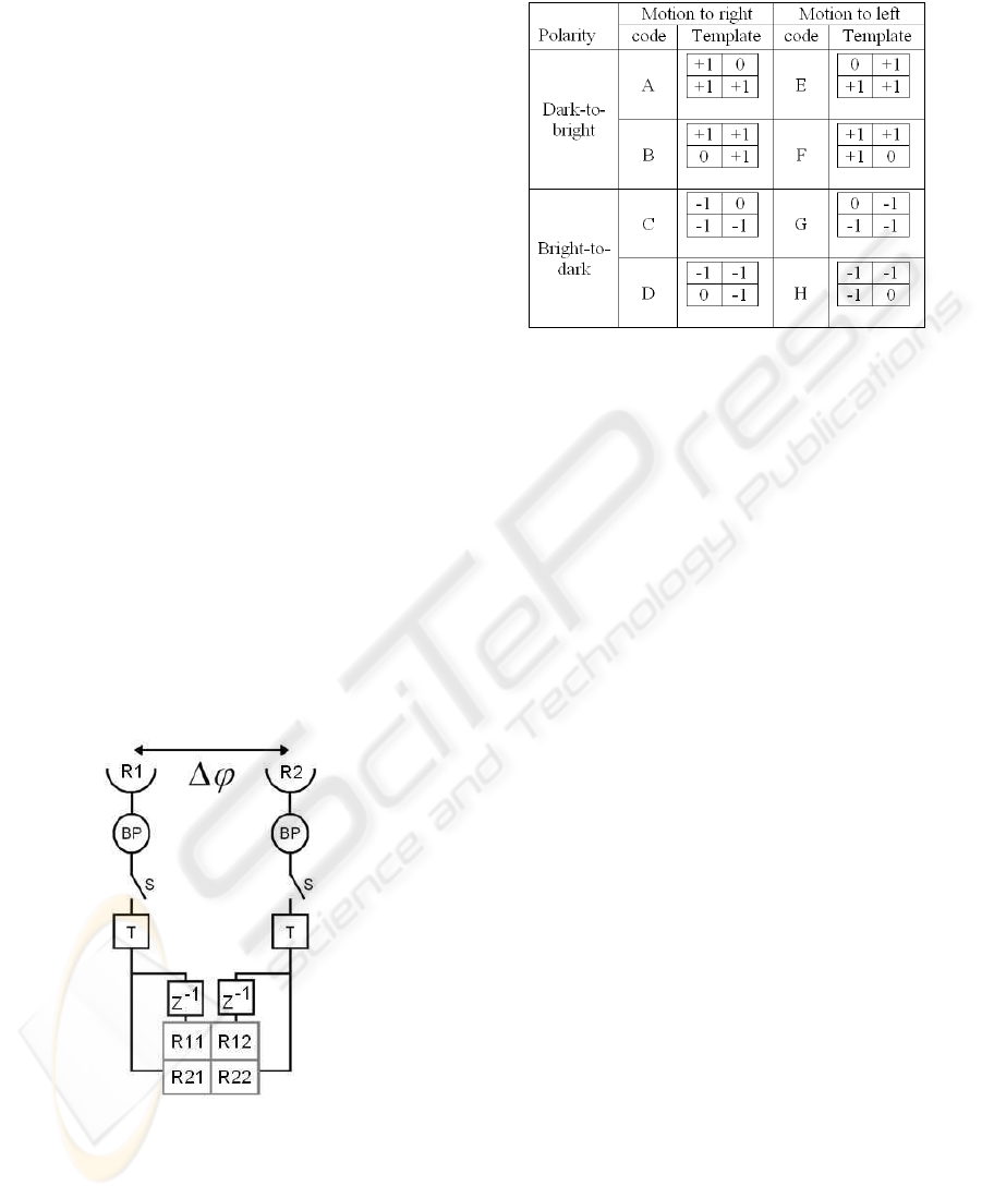
Figure 1: Template model scheme. R1 and R2: Photorecep-
tors, BP: Bandpass filter, T: Threshold function, S: Switch,
z
−1
: Delay function, ∆ϕ: Spatial period.
Figure 1 presents the EMD of the template model.
The visual field is spatially and temporally sampled.
The symbol ∆ϕ is the distance or spatial period be-
tween the photoreceptors. A band-pass (BP) filter
Table 1: List of motion templates.
produces information on changes in the input which is
sampled by a switch. A threshold function then splits
it into 3 states: -1 if the intensity is decreasing, +1 if
it is increasing, 0 otherwise. The current states of the
two channels are transmitted to the bottom row of the
2-by-2 output matrix and the previous states (defined
by a delay z
−1
) are transmitted to the first row of the
matrix.
Over the 81 possible matrices or templates of size
2-by-2, 8 of them indicate the existence of motion to a
specific direction (from one receptor to another). In-
formation about the polarity of the edge transition as
well as beginning and ending of the phenomenon is
also coded as shown in Table 1 (Nguyen et al., 1996).
Thus, this detector is sensitive to direction and
polarity. It gives a simple and easy implementation
model for digital hardware. However the threshold
value has a significant influence on the output and its
optimum value depends on changes in contrast and lu-
minance of the input signal. Also, the velocity sensi-
tivity of the Reichardt model as studied by Dror (Dror
et al., 2001) is lost here by digitizing the output into 3
states. Moreover, the spatial distance between associ-
ated templates, such as templates E and F or A and B
which code the beginning and ending of a transition,
depends on both the spatial length of the transition
and the velocity of the motion. Therefore it cannot
be used in the estimation of the velocity without ex-
tra information. However Nguyen et al. proposed a
tracking algorithm to get velocity with this model as
described in Section 5.
3 HANDLING VIDEO INPUTS
Using the template model to process 2D frames of a
video input requires the definition of the spatiotem-
poral sampling of the EMD and the extension of the
VISAPP 2010 - International Conference on Computer Vision Theory and Applications
448
one-dimensional (1D) direction sensitivity to 2D di-
rection sensitivity.
In order to retain all the details that the input signal
provides, it is logical to match the input spatiotem-
poral resolution to the EMD. Therefore, we choose
∆ϕ as the distance between two pixels and z
−1
as the
frame rate of the video. The filter is here implemented
as a high-pass (HP) filter by simply subtracting the
previous intensity input from the current one and thus
having the sign of the filter output coding the evolu-
tion of the intensity.
To detect all kinds of motion in the video, it is of-
ten proposed to combine two EMD architectures in
an orthogonal fashion such as sensing the x and y di-
rections so that motion in all directions can be recon-
structed. Jun et al. and Tianguang et al. proposed
two 2D EMDs using a 4-pixel X or 3-pixel Γ shape
respectively(Jun et al., 2004; Tianguang et al., 2008).
The association of motion to the output they proposed
is not completely consistent in terms of location. Here
we propose another 5-pixel + shape EMD which has
the advantage of linking motions to the starting point
which is an actual pixel position in the input frame
(see Fig. 2c).
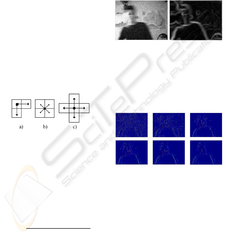
Figure 2: EMD architectures. The dots represent location
to where motions detected are linked. a) Γ, b) X, c) +.
4 FILTER AND MOTION
DETECTION RESULTS
Because of the threshold adjustment and to make the
sensor more robust to noise and sensitive to motion,
a filter has been applied to the input video. A combi-
nation of a Gaussian filter and Sobel operator which
we refer to here as the ”Gaubel” filter will remove
noise and highlight edges. Equation (1) presents the
”Gaubel” filter we designed,
I
out
=
q
[(S
x
∗ G) ∗ I
in
]
2
+ [(S
y
∗ G) ∗ I
in
]
2
(1)
where I
in
is the input image, S
x
and S
y
are
the 3-by-3 Sobel kernels for horizontal and vertical
changes, G is the Gaussian smoothing window and ∗
is a convolution operator.
The standard deviation of the Gaussian equals to
1/6 of the windowsize in order to produce a consistent
smoothing. Normalizing the Gaussian also limits the
range of contrast and luminance at the output and fa-
cilitates the threshold adjustment. The final image is
obtained by calculating the gradient. Figure 3 shows
the result of the application of the filter on a noisy
image.
Figure 3: Filtered input. left: noisy input image, right: fil-
tered image.
The threshold is adjusted to be sufficiently large,
to be sensitiveto changes of intensity of moving edges
and to avoid detecting noise. By testing several Gaus-
sian window sizes (see Fig. 4), a balance can be found
to remove noise (increasing the size) and keep motion
locations as precise as possible (decreasing the win-
dow size). Finally, it is worth noting that using an
edge detection operator gives more features to detect.
Figure 4: Output of the motion detector with filtered in-
put for different Gaussian window sizes. Only left and right
motion direction templates are displayed in color-coded for-
mat. The only moving object in the input is the body mov-
ing from left to right. The window sizes used, from left to
right top to bottom are 7, 11, 17, 21, 27 and 37.
A test of the motion detector in real-time has been
realized. Using a smaller Gaussian window size in
order to increase the processing time of each frame,
led to a noisy output as all frames cannot be handled
at a rate of 20 f ps (see Fig. 5).
SMART VISION SENSOR FOR VELOCITY ESTIMATION USING A MULTI-RESOLUTION ARCHITECTURE
449
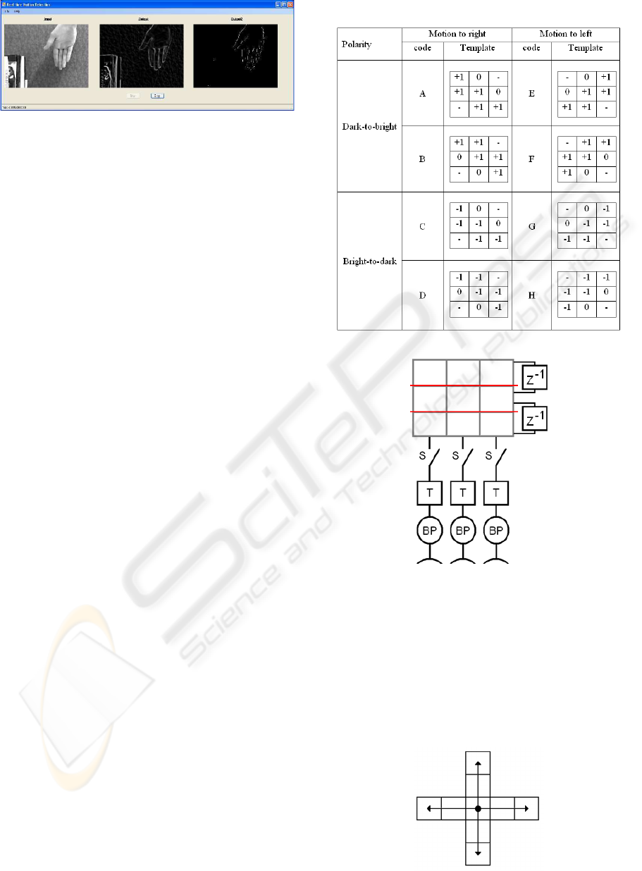
Figure 5: Real-time implementation. A code templates are
displayed in the output. Only the hand is moving to the
right direction. left: input image, middle: filtered image,
right: output of the motion detector.
5 ELEMENTARY VELOCITY
DETECTOR
Use of the template model for velocity estimation
has been realized in the past by tracking templates
and linking them over space and time (Nguyen et al.,
1996). The search space defined directly governs the
velocity range that the estimator is able to track. Such
a method gives an accurate estimation but as the track-
ing process depends on the searching step and on the
number of features to track, it is impossible to de-
termine how long the algorithm will take to process
an unknown input. This phenomenon would be even
worse if dealing with video inputs. Because the pro-
posed system aims to be implemented in real-time, we
need a solution which uses a defined time to process
any input frame.
5.1 Template for Velocity
To be able to estimate velocity, the matching of at
least two templates in space and time needs to be
achieved. In order to remove any tracking process or
search space, we havedesigned a newfamily of veloc-
ity dependent templates. Those are obtained by link-
ing two motion templates in space and time to gen-
erate 8 new ones as described in Table 2. To achieve
such a match the elementary detector needs to be re-
viewed by implementing an extra photoreceptor in the
fashion described in Fig. 6.
The new velocity templates are made out of 3-by-
3 matrices with the top row generated by an extra de-
lay. This means that our new features are only able
to match motion templates (of same code) over one
pixel space difference and one frame temporal differ-
ence. In other words, this architecture is sensitive to
an elementary velocity of one pixel per frame (1 ppf).
We also have extended the elementary detector ar-
chitecture to be able to process video inputs. The Ele-
mentary Velocity Detector (EVD) is shown in Fig. 7.
This one keeps the advantages of our EMD in terms
Table 2: List of velocity templates.
Figure 6: Velocity template model Scheme.
of linking the velocity to the starting point which is an
actual pixel in the input frame. Finally, the direction
of velocity motion is coded with colors. The output
color code is as follows: right direction velocities are
displayed in red color, up in purple, down in yellow,
left in cyan, down and right in orange, up and right in
pink etc.
Figure 7: EVD architecture.
VISAPP 2010 - International Conference on Computer Vision Theory and Applications
450
5.2 Multi-Resolution Velocity
Estimation Architecture
The EVD model provides a tool to estimate direc-
tional velocities of an entire video frame with a fixed
processing time. However it has one main disadvan-
tage in terms of the range of velocities detected. In
order to use the same EVD to estimate other veloci-
ties, a multi-resolution architecture is set up (see Fig.
8 below).
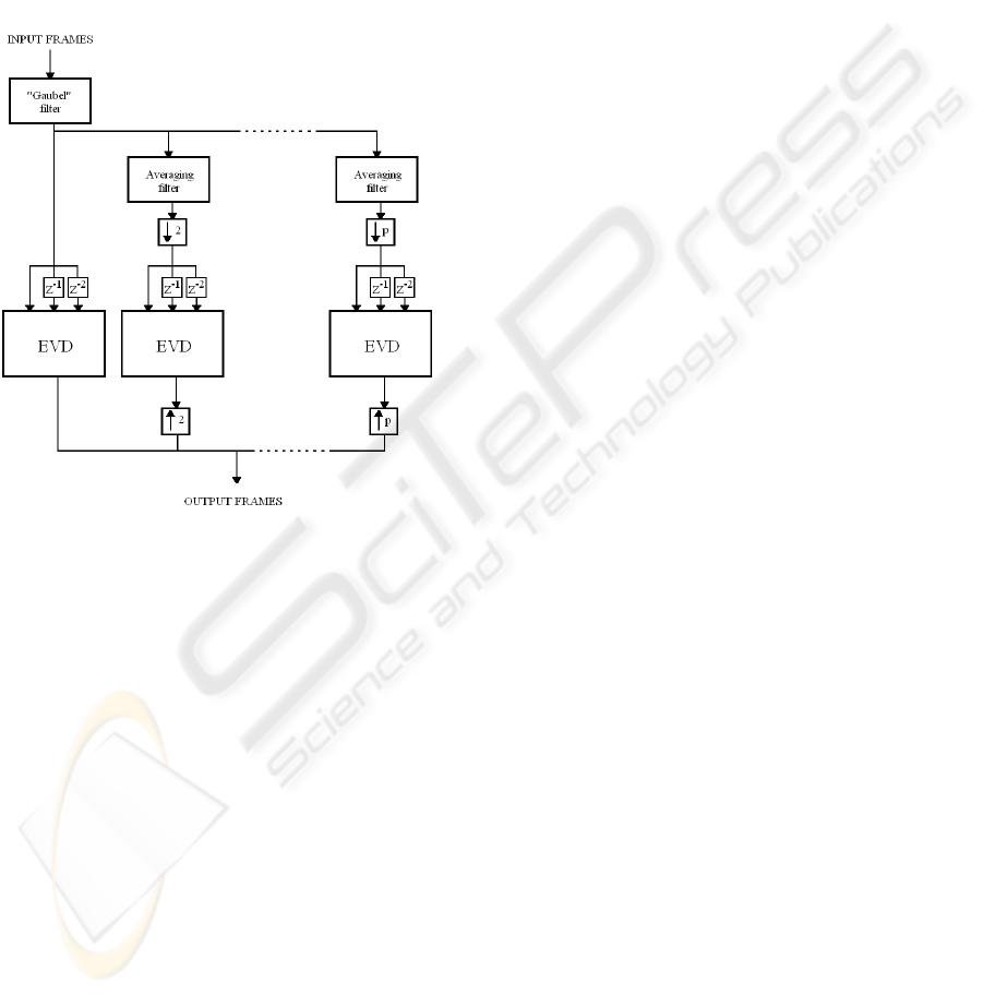
Figure 8: Multi-Resolution Architecture Scheme.
The frames are processed by the ”Gaubel” filter
and then transmitted to each resolution channel to be
processed in parallel. To lower the resolution of the
input, an averaging filter is implemented in each chan-
nel. The convolution kernel size used is related to
the channel resolution. Then each averaged image is
sub-sampled to obtain the channel resolution. In or-
der to detect the velocity templates, three consecutive
frames are needed. Two delays are therefore imple-
mented in front of the EVD. The presence of velocity
templates is then checked by the EVD for each pixel
and the output image is produced. This leads to one
image for each resolution processed. Finally, to group
all these results in one final frame, lower resolutions
are up-sampled to match the original input frame size
and are all combined together. The up-sampling is
simply realized by expanding each pixel to its sur-
rounding area.
By using the EVD on a lower resolution input, a
higher velocity can be estimated. For example, a ve-
locity of 2 ppf at a M-by-N resolution will be esti-
mated as being 1 ppf at a resolution of M/2-by-N/2
and therefore will be sensed by the EVD. Thus veloc-
ity from 1 ppf and higher can theoretically be esti-
mated by this architecture.
A characteristic of this model which can be con-
sidered as an advantage is that higher velocities are
represented by bigger squares in the combined out-
put.
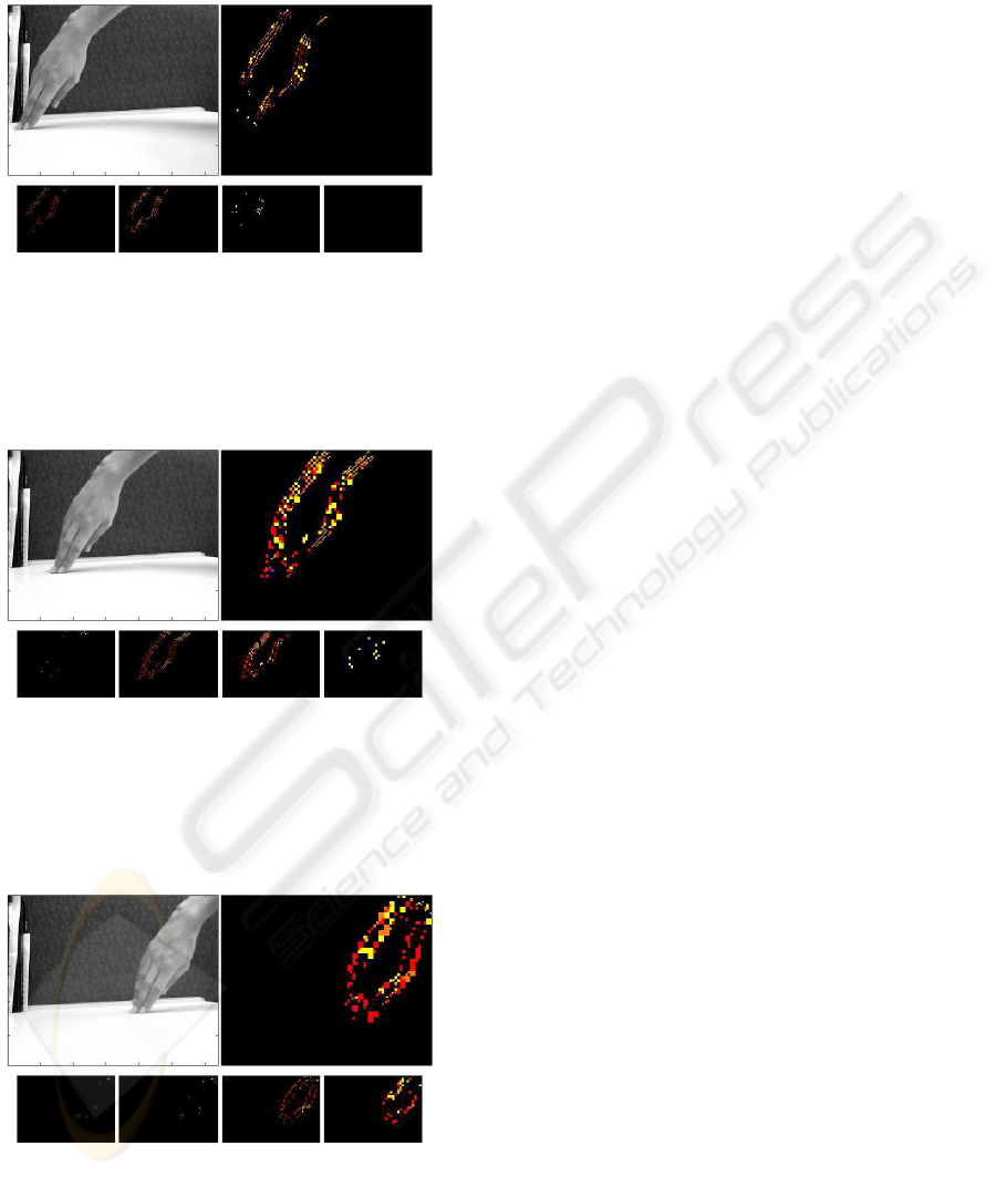
5.3 Results
Figures 9 to 11 display results of the final multi-
resolution architecture using 4 different resolutions.
All the results were produced using the same input
video which displays a hand accelerating to the right
direction.
In Figure 9, the EVD processing the original reso-
lution divided by two is the one displaying more tem-
plates. This means that according to the detector, the
hand is moving at around 2 ppf. In Figure 10 the
hand appears to be moving at around 3 ppf (features
mainly detected at 2 ppf and 4 ppf) and in Figure
11 at around 6 ppf. Based on the fact that figures are
sorted in chronological order, these results are consis-
tent, considering that the hand is actually accelerating.
By bringing outputs together, we can see that al-
most the entire object edges are displayed, this despite
detection of the entire range of velocities is not imple-
mented (3 ppf, 5 ppf, 6 ppf etc.).
An advantage of this architecture is the ability
to estimate a global object motion velocity using in-
formation on each resolution processed by the EVD,
meanwhile keeping all velocity componentsof the ob-
ject, such as a finger moving independently from the
hand.
6 CONCLUSIONS
In this paper, an insect vision based motion detection
technique has been extended to velocity estimation.
A filter has been used to make it more robust and re-
sponsive to moving edges. We also have introduced
the concept of the Elementary Velocity Detector using
velocity templates. This one has been implemented
on a multi-resolution architecture and has been suc-
cessfully tested. The simulations and experiments
demonstrate that this elaborated model produces con-
sistent and promising results. Thus, this simplistic in-
sect inspired algorithm, ideal for parallel computing,
provides information exploitable for specific applica-
tions without need for precise directional and veloc-
ity information. However as we are willing to use
more realistic video inputs, i.e. complex backgrounds
SMART VISION SENSOR FOR VELOCITY ESTIMATION USING A MULTI-RESOLUTION ARCHITECTURE
451
or moving cameras, a further adaptation to change in
contrast and luminance would be required.
Figure 9: Example of input and outputs of the EVD archi-
tecture. top left: input frame, top right: final output, bottom
left: output at original resolution, bottom middle left: out-
put at original resolution/2, bottom middle right: output at
original resolution/4, bottom right: output at original reso-
lution/8.
Figure 10: Example of input and outputs of the EVD archi-
tecture. top left: input frame, top right: final output, bottom
left: output at original resolution, bottom middle left: out-
put at original resolution/2, bottom middle right: output at
original resolution/4, bottom right: output at original reso-
lution/8.
Figure 11: Example of input and outputs of the EVD archi-
tecture. top left: input frame, top right: final output, bottom
left: output at original resolution, bottom middle left: out-
put at original resolution/2, bottom middle right: output at
original resolution/4, bottom right: output at original reso-
lution/8.
REFERENCES
Baker, S., Scharstein, D., Lewis, J., Roth, S., Black, M.,
and Szeliski, R. (2007). A database and evaluation
methodology for optical flow. In Proceedings of the
IEEE Int. Conf. Computer Vision, pages 1–8.
Dror, R. O., O’Carroll, D. C., and Laughlin, S. B. (2001).
Accuracy of velocity estimation by reichardt correla-
tors. J. Opt. Soc. Am. A, 18(2):241–252.
Harrison, R. R. (2005). A biologically inspired analog ic for
visual collision detection. IEEE Trans. Circuits Syst.
Regul. Pap., 52(11):2308–2318.
Hassenstein, B. and Reichardt, W. (1956). Functional struc-
ture of a mechanism of perception of optical move-
ment. In Rosenblith, W. A., editor, Proc. Int. Cong.
Cybern., pages 797–801, Namur.
Horridge, G. A. (1990). A template theory to relate visual
processing to digital circuitry. In Proc. R. Soc. Lond.,
volume Vol. B 239, pages 17–33.
Iida, F. and Lambrinos, D. (2000). Navigation in an au-
tonomous flying robot by using a biologically inpired
visual odometer. In Proc. SPIE Sensor Fusion and
Decentralized Control in Rob. Syst. III, volume Vol.
4196, pages 86–97.
Jun, Y., Dong-Guang, L., Hui-Min, F., and Zhi-Feng, L.
(2004). Moving objects detection by imitating bio-
logic vision based on fly’s eyes. In Proc. ROBIO 2004
IEEE Int. Conf. Rob. and Biomim., pages 763–766.
Nakamura, E., Ichimura, M., and Sawada, K. (2002). Fast
global motion estimation algorithm based on elemen-
tary motion detectors. In Proc. 2002 Int. Conf. Image
Processing, volume 2, pages II–297–II–300 vol.2.
Netter, T. and Francescini, N. (2002). A robotic aircraft that
follows terrain using a neuromorphic eye. In Proc.
IEEE/RSJ Int. Conf. Intel. Rob. and Syst., volume 1,
pages 129–134 vol.1.
Nguyen, X., Bouzerdoum, A., and Bogner, R. (1996).
Backward tracking of motion trajectories for veloc-
ity estimation. In Proc. 1996 Australian and New
Zealand Conf. Intelligent Information Systems, pages
338 – 341.
Riabinina, O. and Philippides, A. O. (2009). A model of
visual detection of angular speed for bees. J. Theor.
Biol., 257(1):61–72.
Sarpeshkar, R., Kramer, J., Indiveri, G., and Koch, C.
(1996). Analog vlsi architectures for motion process-
ing: from fundamental limits to system applications.
In Proc. IEEE, volume 84, pages 969–987.
Tianguang, Z., Haiyan, W., Borst, A., Kuhnlenz, K., and
Buss, M. (2008). An fpga implementation of insect-
inspired motion detector for high-speed vision sys-
tems. In Proc. IEEE Int. Conf. Rob. and Autom., pages
335–340.
Zanker, J. M., Srinivasan, M. V., and Egelhaaf, M. (1999).
Speed tuning in elementary motion detectors of the
correlation type. Biol. Cybern., 80(2):109–116.
VISAPP 2010 - International Conference on Computer Vision Theory and Applications
452
