
DEVELOPMENT A MATRICIAL NUMBER METHODS
PROCESSOR IN A VIRTUAL LABORATORY TO STUDY OF
LINEAR CALCULATIONS OF STRUCTURES
José Miguel Martínez Jiménez, Pilar Martínez Jiménez
Department of Continuous Mechanic, Department of Applied Physics, University of Córdoba, Spain
José Miguel Martínez Valle, Alvaro Martínez Valle
Department of Continuous Mechanic, University of Córdoba, Spain
Keywords: Structures, Linear Calculation, Elasticity, Matrix Structural Analysis, Simulation.
Abstract: In this work is presented an introduction to the main design features of a computer-aided educational
package addressed to students of the final years of Mechanical Industrial Engineering. The software
includes interrelated tutorial, computer simulations and test questions in which graphical outputs, hypertexts
and animations are widely used. The package is devoted to the simulation study of the Calculation of
Structures. The application includes the representation of virtual environments in 3D and lineal calculation
methods which result a virtual laboratory which aim is the representation and calculation of stresses and
deformations in structures, as well as giving the user access to information on the degree of training
reached. The software has all the following features: an integrative character, self-evaluation tests, and a
personalized and active learning process, adaptability to teacher’s aims, versatility as a teaching tool,
multimedia resources, and simplicity. This study has been completed with final-year students at the Superior
Polytechnic School of Cordoba (Spain), with highly favourable results when compared with students who
did not use the software.
1 INTRODUCTION
The future presents itself as a continuous learning
process in a rapidly changing world.
Simulation is the practice of generating models
to represent a system in the real world or in
hypothetical future worlds. The reasons why
simulation has been widely employed are, among
others, the degree of realism that can be included in
the simulation models and the ease with which these
models can be explained.
Computers can be used as a complementary tool
in the learning by discovery process (Clive L.Dym,
2004). By using the computer as a simulator of
phenomena, the student can discover models that
initially remained concealed (Murphey TD, 2008,
Balamuralithara, B. C. 2009).
The creative process of designing the structure of
a building involves imagining the characteristics of
the materials to be used, the dimensions of the
resistant elements which make up that structure and
the structural typology suitable for the building
problem to be solved (Anderheggen, E. Et al. 2005).
In teaching, the software used are, first closed
programmes as ANSYS, ROBOT, etc., other
calculation programmes with a general purpose
generally written in FORTRAN language, included
in specialized texts which permit the user to adapt
and manipulate them but which do not include
interactive environments (Livesley, 1970) and
finally, educational software in which text files
created by it can be directly imported to the FEM
software ANSYS so as to analyze stress distribution
of the shaft (Álvarez-Caldas, C. Et al. 2006) .
With the aim of facilitating the learning of the
student of Structure Calculation we have created a
multimedia virtual laboratory (VisualBasic vs. 6.0,
C++ and Flash) to permit the making of calculations
and the visualization of graphic results, as well as
animations and photographs. The advantage of our
system with similar ones ( Álvarez-Caldas, C. Et al.
427
Miguel Mart
´
ınez Jim
´
enez J., Mart
´
ınez Jim
´
enez P., Miguel Mart
´
ınez Valle J. and Mart
´
ınez Valle A. (2010).
DEVELOPMENT A MATRICIAL NUMBER METHODS PROCESSOR IN A VIRTUAL LABORATORY TO STUDY OF LINEAR CALCULATIONS OF
STRUCTURES .
In Proceedings of the 2nd International Conference on Computer Supported Education, pages 427-430
Copyright
c
SciTePress
2006), is that we have developed and integrated a
processor, MOSOBA, which aims either to provide
the expert with the storage of data derived from the
creative process, or to didactically guide the non
experienced person in the anticipation of forms and
materials.
2 VIRTUAL LABORATORY
DESCRIPTION
In the computer application developed, a series of
sections has been included among which tutorials
and simulations of problems posed stand out.
When initiating the laboratory the first decision
the student must adopt is that of evaluating his/her
level of knowledge on the theme being studied. For
this, the program computer offers the possibility of
reviewing previous concepts which the student
should have acquired in previous courses in the Area
of Mechanics of continuous media and Resistance of
materials, and/or to study the tutorial expressly
related to the simulation in course (Zienkiewicz,
1980; Zienkiewicz et al., 1994).
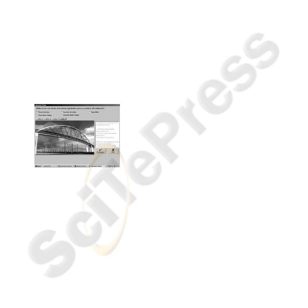
Figure 1: Real building cases.
The activity carried out consists of presenting to
the student, through photographs incorporated into
the laboratory, a real building case already
constructed, for example an industrial hangar, a
sports stadium, etc. (Figure 1). Once the prescribed
discretization has been studied, the main
characteristics of the structural typologies to which
the building in question belongs can be found in the
tutorial, as well as the possible modifications which
can be conceived in supports, joints, load states etc.
The calculation (linear) module called Mosoba,
developed by our researchers group, is the one
which permits the carrying out of the actual
simulation and supplies lists and graphics of stresses
and deformed lines of the different situations which
have been conceived. Mosoba is a processor which
aims either to provide the expert with the storage of
data derived from the creative process, or to
didactically guide the non experienced person in the
anticipation of forms and materials.
Mosoba has been developed in a Windows
environment, directed towards the resolution of
different typologies of bar structures: articulated and
rigid, flat and spatial, and grid, nodes, in which three
well defined stages can be differentiated: pre-
process, calculation and post process, it is being in
the second and third stages when the verification and
simulation necessarily prior to the construction are
produced.
Finally, an Evaluation module has been included
which permits the teacher to monitor the student’s
learning process in relation to the characteristics and
suitability of the structural typology adopted, as well
as on the degree of optimization achieved according
to the solution selected.
3 DESCRIPTION OF THE
MOSOBA MATHEMATICAL
PROCESSOR
The processor Mosoba is only wished to be a faithful
reflection of a methodical and methodological
application in relation to the matrix calculation of
structures and bars and with the calculation
programming coherent with that theory. Thus it has
no other aim than to set up a database which can be
visualized by means of the option “see Data file”
(file in text) in Edition of the Tools bar, which
contains in an orderly form: the name of the
structure and typology to which it belongs, abscissa,
ordinates and heights (if necessary) of the structure
nodes, types of different bars making up the
structure, definition of all the bars, loads on nodes,
and, if appropriate, on the bars themselves, as well
as the identification of the coerced nodes.
As has been stated, Mosoba arose with a didactic
vocation but that does not prevent it from being a
fast, powerful pre-processor, capable of easily
resolving complex and real cases, and, of course,
most of those which can appear in professional
practice. At this moment we are not referring to the
capacity of resolution of problems with a large
number of unknowns, but, on the other hand, to the
agile, attractive and graphical preparation of the data
which should be included in the file “Data” and
which we shall represent, in a Windows screen, as
we go on inserting them.
Although we shall now mostly refer to the cases
of flat structures, which are the most frequent, it
CSEDU 2010 - 2nd International Conference on Computer Supported Education
428
should not be lost from view that the same ideas
have been transferred to spatial ones. Once the
structural type to be considered has been selected,
the first data to be inserted will be those relative to
the position of the nodes in a specific reference
system, an operation which can be executed both by
supplying the coordinates of the nodes and clicking
the mouse at the point indicated.
Although this insertion of the nodes is
interactive, handy and sufficient for a large amount
of cases, for example the reticular structures of rigid
nodes, there are other cases, like the planar parabolic
truss with articulated nodes in Figure 2, in which, for
having a large number of nodes and not fitting the
vertices of a reticule, the insertion of the nodes by
coordinates would be troublesome. For these cases
the facility for automatically generating a set of
nodes regularly spaced over one curve has been
conceived. The possible curves are either flat conical
ones or a generic one defined by a polynomial of up
to a fourth order. In the spatial cases similar criteria
are followed (Figure 3).
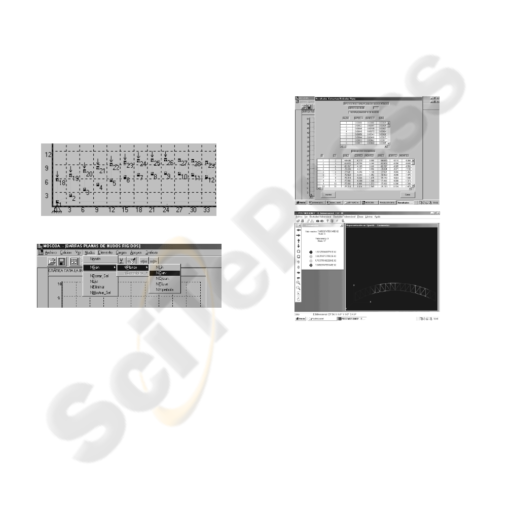
Figure 2: Planar parabolic truss.
Figure 3: Flat bars with rigid nodes.
To control the correct insertion of data we have
provided the options: List the nodes, erase all the
nodes or erase only the nodes that we select
previously, permitting us to ensure their definition,
or, if necessary, to correct the mistaken one. Next,
we shall define the bars, first the geometric and
mechanical characteristics of one or several bars
whose initial and final nodes will be indicated next.
The latter can be indicated in the corresponding
dialogue square or by clicking the mouse on the
initial and final node of each bar, with the possibility
of choosing, or not, to visualize the corresponding
numbering.
In the same way as in the case of the definition
of the nodes, we have set up the facility to generate
elements systematically, starting from a previously
defined element. Repeating this operation a few
times can provide us with the definition of all the
bars, which may be a great deal, of structures like
that of the example, in which once the bar 1-2 of the
bottom bar has been defined, the facility that we
mentioned allows us to generate the 15 following
ones on the mentioned bars (2-3 to 16-17).
For the definition of loads and coercions we have
the same options as those mentioned for nodes and
elements, i.e. we can define them individually in
specific nodes, generate them automatically in
several nodes with a single order, we can list them
and erase them, etc.
For the case of flat structures with rigid and grid
nodes, there is a possibility of inserting distributed
and occasional loads, in any number, on the bars
(Figure 4).
Figure 4: Numerical and graphical result of the study.
4 DIDACTIC EVALUATION OF
SOFTWARE
This virtual laboratory has been used, from a
didactic point of view, as a computer-simulated
laboratory experiment, with 3
rd
year technical
engineering students and for five years running.
In order to assess the educational value of the
program, a comparative analysis was made of the
learning results achieved by students who had
worked with this tool (experimental groups GE1 and
GE2) and other students at the same level who
DEVELOPMENT A MATRICIAL NUMBER METHODS PROCESSOR IN A VIRTUAL LABORATORY TO STUDY
OF LINEAR CALCULATIONS OF STRUCTURES
429

followed a traditional teaching method (control
groups GC1 and GC2) based on a theoretical
exposition and problem resolution. The two
experimental group students did the problem
resolution classes and worked in small groups for
various sessions with the simulation program,
following the instructions in an activity program
guide, which included different kinds of activities.
The evaluation of the learning program was
made through an analysis of the individual reports of
each student and a complementary questionnaire.
The same evaluation process was followed with the
control group students. The two experimental groups
(GE1=65, GE2=70) and the two control groups
(GC1=72, GC2=67) were similar in their average
age, level of studies (3
rd
year of Engineering) and
previous knowledge.
The analysis of the evaluation data was made
from a classification of the results obtained by the
students organized in four different learning
categories: I (deficient), II (acceptable), III (good)
and IV (very good). On analyzing the first results it
was observed that the individuals in the experiment
groups generally achieved better results than those
of the control groups.
From these results, some facts worthy of mention
can be deduced: 1) the evaluation process gave
similar results in the two control groups GC1 and
GC2, so that the system used can be considered as
being reliable. 2) Similar results were observed in
the experiment groups GE1 and GE2, using the same
evaluation method, so that we can consider the
learning process to be homogeneous. 3) Statistically
significant differences were noted between the
degrees of progress of the experiment groups with
respect to the control groups. The greatest
differences were seen in level I (deficient) this being
much greater in the control groups, and in level III
(good), notably higher in the experiment groups.
From these facts, it is deduced that the
instruction process followed in the experiment
groups enabled students to achieve a higher progress
level than in the control groups and that the program
used constitutes a useful instrument for improving
the learning process.
5 CONCLUSIONS
A computer application which objective is the
identification and numerical and graphical study of
Structures has been developed. A similar structure to
other specific Calculation software has been
followed: CYPE, TRICALT, etc. or to that of
analysis by the Finite Element Method, ANSYS,
ROBOT, etc. (pre-process, resolution and post
process).
The MOSOBA processor is intended to be
programme for training prior to the use of more
specific software. It has been created in a
WINDOWS environment to make it more attractive
to the novice and permits the resolution of a
structure very easily and in a short interval of time.
That is to say, it is wished to keep its didactic nature
although it is provided with enough power to tackle,
in combination with specific programmes on
reinforced or prestressed concrete or metal
structures, complex problems with the added
advantage of being able to control, in a highly
personal way, the value of the parameters taken into
account in the structure’s design.
This study has been completed with final-year
students at the Superior Polytechnic School of
Cordoba (Spain), with highly favourable results
when compared with students who did not use the
software.
REFERENCES
Anderheggen, E. and Pedron, C.; E-Teaching and E-
Learning Structural Design Conference Proceeding
Paper, Computing in Civil Engineering, July 12.15,
2005, Cancun, Mexico (2005).
Álvarez-Caldas, C., San Román García, J. L. Belén Muñoz
Abella, Quesada González, A.; Arguelles Alvarez, R.
Educational software to design shafts and analyze
them by FEM, Computer Applications in Engineering
Education, 15, 1, pp. 99-106, (2007).
Balamuralithara, B. C. Woods, P., Virtual Laboratories in
Engineering Education: The Simulation Lab and
Remote Lab, Computer Applications in Engineering
education, 17, 1, pp. 108-118 (2009).
CIive L. Dym, Design, Systems, and Engineering
Education, International Journal in Engineering
Education, 20, 3, pp. 305-312, (2004).
Livesley, R.K., Métodos Matriciales para el cálculo de
estructuras, Ed. Blume, Madrid- España (1970).
Murphey TD, Teaching rigid body mechanics using
student-created virtual environments, IEEE
Transactions on education, 51 n 1, pp. 45-52, (2008).
Zienkiewicz, O.C., El Método de los elementos finitos, Ed.
Reverté, Barcelona- España (1980).
Zienkiewicz, O.C. y L.R. Taylor, El Método de los
elementos finitos. McGraw-Hill y CIMNE, Barcelona-
España (1994).
CSEDU 2010 - 2nd International Conference on Computer Supported Education
430
