
CAPACITIVE SENSING FOR PULSE RATE MONITORING
R. Niall Tait
Dept. of Electronics, Carleton University, 1125 Colonel By Drive, Ottawa, Ontario, K1S5B6, Canada
Keywords: Capacitance, Sensor, Pulse.
Abstract: This paper describes pulse rate monitoring using capacitive electrodes on finger or wrist. The technique
uses a single frequency measurement suitable for low cost and low power applications. The system may
enable convenient, comfortable, and continuous monitoring. Pulsatile flow resulted in approximately 5-10
fF of capacitance variation, a level easily measured using inexpensive capacitance measurement integrated
circuits.
1 INTRODUCTION
Automated pulse and heart rate measurements have
become commonplace with the development of
personal training and health monitoring devices.
These devices are accurate and easy to use.
However ECG based systems require either a chest
strap which may be uncomfortable or inconvenient,
or require use of a finger touch sensor and therefore
do not provide continuous monitoring. Pressure
based systems require a finger, wrist, or arm cuff
that periodically inflates, can be uncomfortable, and
does not provide continuous monitoring. Optical
systems (pulse oximeters) require an optical
transmitter with adequate intensity output to
penetrate tissue, and although many battery operated
models are available, they are not compatible with
very low power operation.
Bioimpedance measurement methods have found
many applications, however they have seldom been
applied to simple pulse rate monitoring. One reason
may be that obtaining the wealth of information
available from a complex impedance measurement
requires at least four contact electrodes usually using
gel on at least one limb, wired to precision bench top
electrical instrumentation (Bayford 2006). However
if capacitance is the only parameter to be measured,
the situation is changed.
Capacitance sensing has become very common in
recent years. Traditionally capacitance sensing
suffered from a reputation of being susceptible to
parasitic effects and requiring unstable high input
impedance circuitry. Most measurements involved
bridge circuits (Mohanty 2004) or network analyzers
(Ferrier 2008). However those complexities have
largely been overcome using microcontroller based
capacitance measuring circuits. These sensors are
now widely used in consumer electronics for non-
contact switches, sliders, and track pads. In addition
to the benefit that capacitance switches do not
require direct electrical contact, they also draw no
direct current in any state, and are therefore suitable
for low power applications. With no direct current
the devices are inherently low noise, although
support circuitry may not share this benefit.
These now ubiquitous capacitance sensing IC’s
have been demonstrated in many applications
including chromatography systems (Takeuchi
2008). They also have potential to be used in finger
or wrist band pulse rate monitors, enabling low cost
and very low power operation for ambulatory
monitoring, or in combination with other sensors for
more complete vital sign monitoring.
2 METHODS
2.1 Experimental
In order to test the feasibility of measuring pulse rate
using finger capacitance measurement, the Analog
Devices AD7746 capacitance to digital converter
was used. This integrated circuit is specified to
provide 4fF accuracy and 4 aF resolution at a 32kHz
measurement frequency, and has a 2 wire I
2
C
compatible digital interface (Analog Devices, Inc.
2005). The IC is available as part of an evaluation
board, using a Cypress Microsystems CY7C68013
215
Niall Tait R. (2010).
CAPACITIVE SENSING FOR PULSE RATE MONITORING.
In Proceedings of the Third International Conference on Biomedical Electronics and Devices, pages 215-218
DOI: 10.5220/0002750902150218
Copyright
c
SciTePress
Ez-USB microcontroller for the I
2
C to USB interface
to a personal computer for programming and data
acquisition (Cypress Semiconductor Corporation
2005).
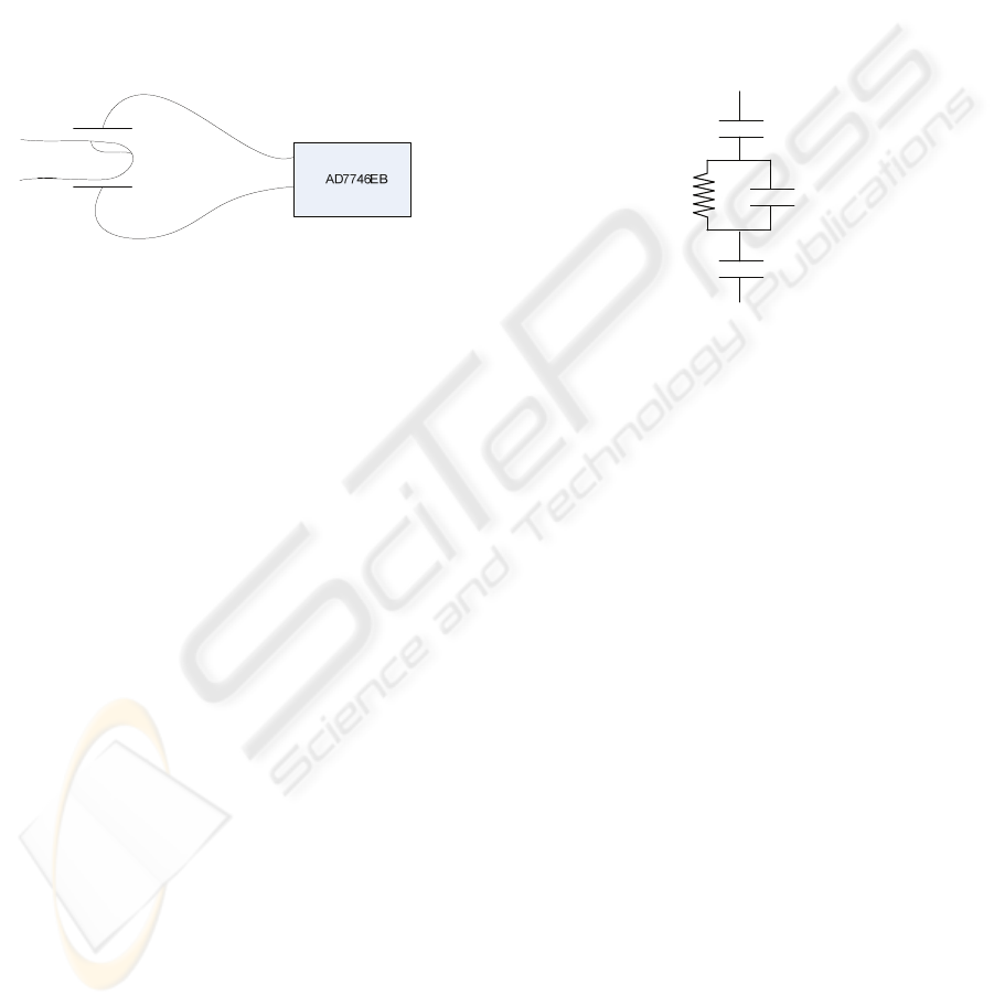
A schematic of the measurement system is
shown in Figure 1. A key factor enabling the
measurement is close contact between the finger and
electrode. This can be achieved by incorporating
electrodes into a finger clip similar to a pulse
oximeter, or incorporating them into a cuff using a
fabric hook-and-loop closure. The cuff approach
can be less bulky and more secure than the clip,
although the cables may be inconvenient.
Figure 1: Schematic of finger pulse measurement.
Excitation and measurement electrodes were
constructed from copper tape strips 6 mm wide and
14 mm long covered with dielectric tape. Electrodes
were adhesive mounted on a fabric hook-and-loop
cuff for attachment to the finger. Electrodes were
connected to the AD7746 using coaxial cables
approximately 400 mm long. Measurements were
completed with the subject’s arm resting on a table
top approximately 20 cm below the level of the
heart. The capacitance measurement circuit was set
up using the evaluation board software (Analog
Devices, Inc. 2005). The IC was set to a typical
configuration with one excitation electrode driven
by excitation channel B with an amplitude of V
DD
/2,
and one input electrode connected to the positive
terminal of input channel 1. The capacitance
measurement was then single-ended with continuous
sampling at a rate of 16.1 Hz. No further signal
processing was used.
For wrist measurements, electrodes with
dimensions identical to those used in the finger
monitor were located on either side of the radial
artery. These were also fixed in place using a fabric
hook-and-loop band. The measurement procedure
was identical to the finger measurement.
This work was intended only as an initial
feasibility study for this technique and no efforts
were made to evaluate the effect of position and
motion artifacts, or the variation in results for
different subjects.
2.2 Electrical Model
An electrical model of the pulsatile flow is required
in order to enable discussion of the measured results
with respect to the physical system. At this stage a
simple model of the finger tissue can be used,
replacing it with a parallel capacitance and
resistance. However it is important to include series
capacitance between the finger and electrodes
representing the dielectric and any small air gap.
The model shown in Figure 2 can be easily
evaluated using a circuit simulator, numerical
calculation, or analytical methods.
C
f
R
f
C
e
C
e
Figure 2: Electrical model for finger impedance.
Permittivity of the finger tissue is high, and
depends on the exact composition of the tissue.
However if the relative permittivity is approximately
ε
r
=3000 and the finger diameter is 13 mm, the finger
capacitance using a parallel plate approximation
should be about 170 pF.
The signal to be measured is associated with the
pulsatile nature of the blood flow. The finger is not
a rigid structure, so the increase in blood pressure
during systole should correspond to an increase in
volume of the finger. In addition, if the electrodes
are attached to a rigid band, there will be a
corresponding decrease in the gap between the
finger and the electrodes.
A perceived drawback of a capacitive
measurement is that the signal will be loaded by
both the shunt resistance and the series capacitance
components. The finger resistance will influence the
measured value as it passes current, but provided the
resistance is fairly high and the measurement
frequency is high enough the effect is small. The
dielectric coating on the electrodes and any air gap
between electrodes and skin represent a low
permittivity and small capacitance. However due to
the series connection, these capacitances dominate
the overall impedance of the system regardless of
the measurement frequency. Fortunately, for a pulse
measurement the exact amplitude of the measured
impedance is much less important than the
BIODEVICES 2010 - International Conference on Biomedical Electronics and Devices
216
frequency provided the amplitude is adequate for
measurement.
For a high resistance subject, the measured
capacitance then is expected to be the series
combination of the finger capacitance and the two
electrode capacitances. Using the dimensions for
electrode and finger mentioned above, and an air gap
of 0.5 mm between electrode and skin surface
produces a total capacitance of 0.74 pF. Further
adding a sinusoidal variation of 1% in finger
diameter (and corresponding reduction in gap) a
capacitance fluctuation of about 8 fF is predicted.
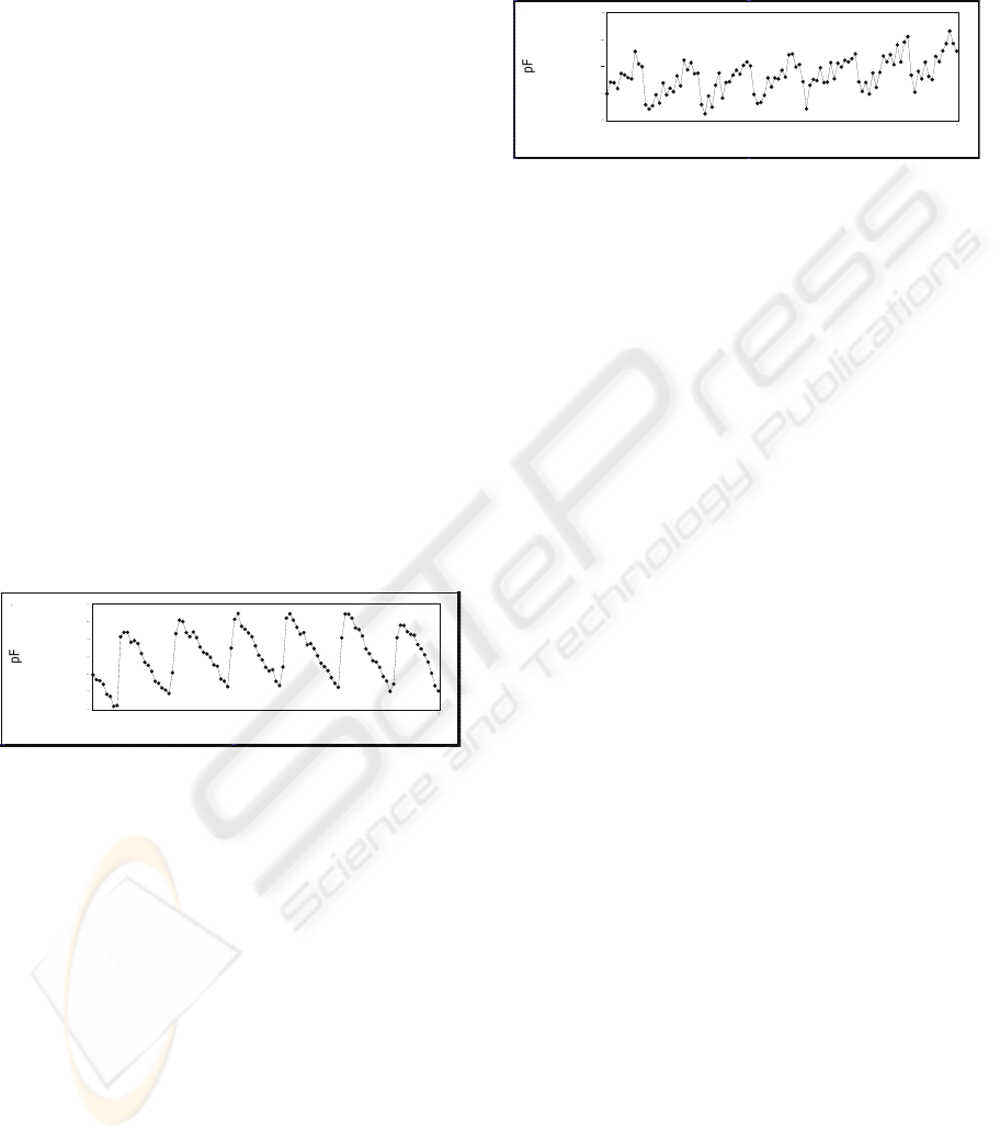
3 RESULTS AND DISCUSSION
Initial experiments were completed using electrodes
on the index finger. The capacitance variation with
time is shown in Figure 3. It corresponds well with
the pulse and shows features similar to a typical
infrared absorption measurement. No attempt was
made to shield electrodes in this measurement, and
the capacitance values are sensitive to parasitic
coupling to nearby objects and to movement of the
subject. These effects require further study, but are
commonly encountered and can be reduced through
improved design and signal processing (Kim 2006).
Figure 3: Capacitance measurement for electrodes
mounted on the finger.
The mean capacitance shown in Figure 3 is 0.565
pF with a fluctuation around 8 fF, which is similar to
the estimate from the electrical equivalent model.
Detailed noise measurements were not completed,
but the RMS noise level in stable operation and with
no finger between the electrodes is less than 100 aF.
The signal was not observed to show significant
variation due to position on the finger or tension in
the cuff. No quantitative measurements were made
to investigate the effect of changing conductivity on
the capacitance measurement.
A second measurement location was investigated
using parallel electrodes held on either side of the
radial artery using a wrist band. With this electrode
arrangement the capacitance is between the facing
edges of the electrodes, and the change is expected
to be lower than with the finger measurement. In
fact the amplitude variation in the capacitance was
found to be similar to the finger measurement,
however the total capacitance and noise level was
higher as shown in Figure 4.
Figure 4: Capacitance measurement for electrodes
mounted on the wrist.
While the pulse can be identified in this signal, an
improvement in the signal amplitude or noise is
required to make this a practical measurement. If
this can be improved the implementation would be
much more convenient for a subject using the sensor
for continuous pulse monitoring as it could be
incorporated in a wristwatch style instrument.
However placement of the electrodes relative to the
radial artery will be much more challenging than
placement of the finger-cuff electrodes.
4 CONCLUSIONS
Capacitive measurement of pulse rate has been
demonstrated to be an interesting technology for low
cost and low power applications. The most
promising results have been found using a finger
cuff containing measurement electrodes which
provided a pulsatile variation of approximately 8 fF.
ACKNOWLEDGEMENTS
This work was supported by the Natural Sciences
and Engineering Research Council of Canada
(NSERC).
REFERENCES
Analog Devices, Inc. AD7745/AD7746 24-Bit
Capacitance-to-Digital Converter with Temperature
Sensor. Norwood, MA, USA: www.analog.com, 2005.
Analog Devices, Inc. AD7746 Evaluation Board.
Norwood, MA, USA: www.analog.com, 2005.
Bayford, R.H. “Bioimpedance Tomography.” Annu. Rev.
Biomed. Eng., 2006: 63-91.
2.095
2.100
2.105
2.110
Time(s)
60
0.560
0.564
0.568
Time(s) 6
0
0.572
2.115
CAPACITIVE SENSING FOR PULSE RATE MONITORING
217

Cypress Semiconductor Corporation. CY7C68013 EZ-USB
FX2 USB Microcontroller. San Jose, CA, USA:
www.cypress.com, 2005.
Ferrier, G.A., Hladio, A.N, Thomson, D.J., Bridges, G.E.,
Hedayatipoor, M., Olson, S., Freeman , M.R.
“Microfluidic Electromanipulation with Capacitive
Detection for the Mechanical Analysis of Cells.”
Biomicrofluidics, 2008: 044102.
Kim, B.S., Yoo, S.K. “Motion artifact reduction in
photoplethysmography using independent component
analysis.” IEEE Transactions on Biomedical
Engineering 53, no. 3 (2006): 566-568.
Mohanty, S.K., Sohn, L.L., Beebe, D.J. “Hybrid
Polymer/Thin Film Impedance System for Label-free
Monitoring of Cells.” EMBS. San Francisco: IEEE,
2004. 2561-2565.
Takeuchi, M., Li, Q., Yang, B., Dasgupta, P.K., Wilde,
V.E. “Use of a Capacitance Measurement Device for
Surrogate Noncontact Conductance Measurement.”
Talanta, 2008: 617-620.
BIODEVICES 2010 - International Conference on Biomedical Electronics and Devices
218
