
KEY EXCHANGE PROTOCOL USING PERMUTATION PARITY
MACHINES
Oscar Mauricio Reyes
Institute of Computer Technology, Hamburg University of Technology, D-21073 Hamburg, Germany
School of Electrical and Electronic Engineering and Telecommunnications,
Universidad Industrial de Santander, Bucaramanga, Colombia
Karl-Heinz Zimmermann
Institute of Computer Technology, Hamburg University of Technology, D-21073 Hamburg, Germany
Keywords:
Parity machine, Synchronization, Cryptography, Key exchange.
Abstract:
In recent years it was shown that two artificial neural networks can synchronize by mutual learning. This fact
can be used in cryptographic applications such as symmetric key exchange protocols. This paper describes
the so-called permutation parity machine, an artificial neural network proposed as a binary variant of the tree
parity machine. A key agreement mechanism based on neural synchronization of two permutation parity
machines will be defined and the security of the key exchange protocol will be discussed.
1 INTRODUCTION
In cryptography, a well-known problem is the secret
key exchange between two parties that have no prior
contact, using an insecure channel (Schneier, 1996).
In this problem, two partners Alice (A) and Bob (B)
want to exchange messages using a public channel.
In order to keep the content secret and to protect it
against an eavesdropper Eve (E), the partners A and
B decide to encrypt their messages using a symmet-
ric encryption algorithm, for which they must share a
common secret key. To this end, there is a large num-
ber of practical key-establishment protocols, which
may be broadly subdivided into key-transport and
key-agreement protocols (Menezes et al., 1996). In
key-transport mechanisms, one party creates or ob-
tains a secret and securely transfers it to the other,
while in key-agreement protocols a shared secret is
derived by both parties as a function of exchanged
information. In both cases, the information that the
attacker E can eavesdrop on the insecure channel is
eventually not sufficient to discover the key.
A key-agreement mechanism based on the neu-
ral synchronization of two parity machines was first
proposed in (Kanter et al., 2002). It takes advan-
tage of the fact that synchronization by mutual learn-
ing is much faster than learning by example (Kan-
ter et al., 2002; Rosen-Zvi et al., 2002a; Rosen-Zvi
et al., 2002b). Such a protocol does not involve large
numbers and methods from number theory (Mislo-
vaty et al., 2002). Instead, it is performed by the
mutual adaptation process between the active partici-
pants as follows: Given two parity machines, one for
each partner A and B, that have the same structure and
parameters. The machines eventually differ in their
initialization weights, and the weights are kept secret
all the time. The machines perform a synchroniza-
tion process so that they eventually end up with the
same weights. For this, the machines conduct a series
of iterations. In each iteration, the machines read in-
put data that are publicly available to both machines
and produce an output that is communicated between
the machines over a public channel. If the synchro-
nization process is successful, i.e., the weights in both
machines are equal, the weights can be used to form
a session key.
The idea to use neural synchronization for a cryp-
tographic key exchange protocol was studied for tree
parity machines and some practical applications were
proposed (Behroozi, 2005; Volkmer and Schaum-
burg, 2004; Volkmer and Wallner, 2005; Volkmer
and Wallmer, 2005a; Volkmer and Wallmer, 2005b).
Moreover, by a suitable choice of parameters, attacks
based on learning only have a small probability of
496
Mauricio Rayes O. and Zimmermann K. (2009).
KEY EXCHANGE PROTOCOL USING PERMUTATION PARITY MACHINES.
In Proceedings of the International Joint Conference on Computational Intelligence, pages 496-501
DOI: 10.5220/0002334704960501
Copyright
c
SciTePress

success (Ruttor, 2006).
If one wants to compare the level of security
achieved by the neural key exchange protocol with re-
spect to other algorithms for key exchange, some as-
sumptions should be made based on Kerckhoff’s prin-
ciple (Menezes et al., 1996):
• The attacker E knows all the messages exchanged
between the partners A and B, but she is unable to
change them so that she can only perform passive
attacks.
• The attacker E knows the structure of the net-
works used to exchange the messages, but she
does not know their initial weights.
• The security of the neural cryptographic protocol
relies on the difference between mutual and uni-
directional learning so that the learning process
need not be kept secret.
2 PERMUTATION PARITY
MACHINES
Permutation parity machines are multi-layer feed-
forward networks proposed as a variant of tree parity
machines with binary weights (Reyes et al., 2009).
2.1 Structure
Let G, K, and N be positive integers. A permutation
parity machine can be considered as a neural network
with K hidden units that are perceptrons with inde-
pendent receptive fields (figure 1).
Each unit has N input neurons and one output neu-
ron. All input values are binary,
x
i, j
∈ {0,1}, 1 ≤ i ≤ K, 1 ≤ j ≤ N. (1)
The synaptic weights are drawn from a pool of bi-
nary data given by a so-called state vector s ∈ {0, 1}
G
,
where G ≥ K · N. More specifically, take an K ×
N matrix π = (π
ij
) whose entries are given as the
images of the one-to-one mapping π : {1,...,K} ×
{1,...,N} → {1,...,G} : (i, j) 7→ π
i, j
. Then assign
the weights by taking the entries of the state vector s
according to the positions given by the matrix entries,
w
i, j
= s
π
i, j
, 1 ≤ i ≤ K, 1 ≤ j ≤ N. (2)
The output of the i-th hidden unit requires to deter-
mine the component-wise exclusive disjunction (ex-
clusive or) between weights and inputs,
h
i
= x
i
⊕ w
i
= (x
i, j
⊕ w
i, j
)
j
, 1 ≤ i ≤ K, (3)
The vectorized random field h
i
provides the number
of positions at which inputs and weights differ,
h
i
= |{ j | x
i, j
⊕ w
i, j
= 1, 1 ≤ j ≤ N}|, 1 ≤ i ≤ K, (4)
w
1
w
K
GFED@ABC
x
1
//
GFED@ABC
h
1
h
1
. . .
GFED@ABC
x
K
//
ONMLHIJK
h
K
h
K
GFED@ABC
θ
N
. . .
GFED@ABC
θ
N
GFED@ABC
σ
1
&&
N
N
N
N
N
N
N
N
N
N
N
N
N
N
. . .
GFED@ABC
σ
K
vv
m
m
m
m
m
m
m
m
m
m
m
m
m
m
m
m
m
m
?>=<89:;
τ
s
π
//
mapping
w
i,j
= s
π(i,j)
Figure 1: General structure of a permutation parity ma-
chine (Reyes et al., 2009).
where | · | denotes the size of a set.
The output of the i-th hidden unit yields a thresh-
old value for the random field h
i
. It equals 1 if the
random field is larger than N/2, and equals 0 other-
wise; that is,
σ
i
= θ
N
(h
i
), 1 ≤ i ≤ K, (5)
where for each nonnegative integer h,
θ
N
(h) =
1, h > N/2,
0, h ≤ N/2.
(6)
The output of a permutation parity machine is given
by the parity of the hidden units,
τ =
K
M
i=1
σ
i
. (7)
The output τ indicates whether the number of active
hidden units (σ
i
= 1) is even (τ = 0) or odd (τ = 1).
For simplicity we only consider permutation par-
ity machines with two hidden units K = 2. Recently,
it was proved that two permutation parity machines
each of which with two hidden units can synchronize
by mutual learning in a finite number of steps (Reyes
et al., 2009).
2.2 Order Parameters and Joint
Probability Distributions
Order parameters are used to describe the correlation
between two permutation parity machines during the
mutual learning process. The level of synchronization
KEY EXCHANGE PROTOCOL USING PERMUTATION PARITY MACHINES
497

can be estimated by using the Hamming distance to
calculate the overlap between the i-th hidden units as
r
AB
i
= N − d
H
(w
A
i
,w
B
i
), 1 ≤ i ≤ K, (8)
while the overlap between the state vectors can be ob-
tained by
R
AB
= G − d
H
(s
A
,s
B
). (9)
The corresponding normalized overlap is given as
ρ
AB
=
R
AB
G
∈ [0,1]. (10)
The probability that exactly r positions of the
weight vector of a hidden unit are drawn from R over-
lapping positions of the corresponding state vector is
given by the hypergeometric distribution as
f
r;G,R,N
=
R
r
G−R
N−r
G
N
, 0 ≤ r ≤ N. (11)
Let q
r,N
denote the probability that two corre-
sponding hidden units in the networks A and B have
overlap r and yield the same output. This probability
is given by (Reyes et al., 2009)
q
r,N
=
2· q
0
r,N
, if N odd,
q
0
r,N
+ q
1
r,N
, otherwise.
(12)
where
q
0
r,N
=
1
2
N
r
∑
m=⌈
r
2
⌉
⌊
N
2
−r+m⌋
∑
n=⌈
N
2
−m⌉
r
m
N − r
n
, (13)
and
q
1
r,N
=
1
2
N
r
∑
m=⌈
r+1
2
⌉
⌊
N−1
2
−r+m⌋
∑
n=⌈
N+1
2
−m⌉
r
m
N − r
n
. (14)
3 KEY EXCHANGE PROTOCOL
BY MUTUAL LEARNING
Two interacting permutation parity machines can syn-
chronize their state vectors via mutual learning by the
following protocol (Reyes et al., 2009): Given two
permutation parity machines, one for each partner A
and B, that have the same structure and parameters;
that is, the length of the state vectors G, the num-
ber of inputs N and the number of hidden units K
are the same in both machines. However, each neural
network starts with a randomly chosen state vector;
these vectors can be different in both machines. The
synchronization process involves two kinds of rounds,
inner and outer rounds.
An outer round consists of a series of inner rounds
that is used to fill an initially empty buffer of length
G position by position in each network. When the
buffers are completely filled, the outer round replaces
the state vector by the respectively filled buffer.
During each inner round the partners perform the
following steps:
• Choose a K × N matrix π and a binary input vec-
tor x = (x
ij
) of length K · N; these data are gener-
ated uniformly at random, are known to both part-
ners and are publicly available.
• Calculate the outputs τ
A
and τ
B
of the machines
A and B according to (7), respectively. Exchange
the outputs using a public channel. If the output
bits τ
A
and τ
B
are equal, we speak of a synchro-
nization step. In this case, each machine takes the
output of the first perceptron, σ
A
1
in A and σ
B
2
in
B, and stores it in the next empty position of the
corresponding buffer. Thus the buffers are simul-
taneously filled bit by bit. Otherwise, the buffers
remain unchanged.
The inner rounds are repeated until the buffers are
completely filled. Then the state vectors are updated
with their buffers and the outer round ends. A new
outer round starts with emptying the buffers and pro-
viding a new series of inner rounds. Two situations
can occur during a synchronization step:
• The outputs of the first hidden units are equal
(σ
A
1
= σ
B
1
) and so the overlap between the buffers
increases (increasing step).
• Otherwise, σ
A
1
6= σ
B
1
and thus the overlap between
the buffers decreases (decreasing step).
This learning process is repeated until the net-
works are eventually synchronized. Upon synchro-
nization, the state vectors can reach either a paral-
lel alignment given by s
A
= s
B
or an anti-parallel
alignment given as s
A
= s
B
, where the binary com-
plement is taken component-wise. An anti-parallel
alignment is produced as a result of a sequence of
only decreasing steps and requires the number of in-
puts per hidden unit to be odd, while a parallel align-
ment emerges by a series of only increasing steps and
can occur whether the number of inputs per hidden
unit is even or odd (Reyes et al., 2009). In case of an
anti-parallel alignment, an additional learning step is
required to make both state vectors equal. This step
can be provided by a simple parity verification which
can be performed without an additional exchange of
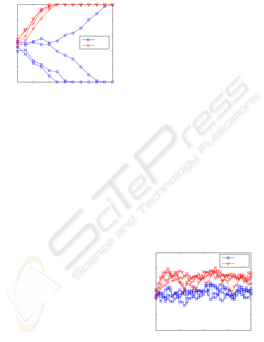
information between the networks. Figure 2 shows
the evolution of the normalized overlap ρ
AB
during
the synchronization process obtained by simulations.
Observe that as the overlap moves away from 0.5, it
rapidly attains the values of 0 or 1 which indicate the
IJCCI 2009 - International Joint Conference on Computational Intelligence
498
Outer rounds
Normalized overlap ρ
N = 3
N = 4
0 2 4 6
8 10 12
0
0.2
0.4
0.6
0.8
1
Figure 2: Evolution of the normalized overlap ρ = ρ
AB
dur-
ing synchronization obtained from simulations with G =
128.
synchronization of the two machines (after 12 or less
outer rounds).
The only secret in this protocol is represented by
the initial values of the state vectors. However, an au-
thentication method can be implemented if both par-
ties use separate, but identical pseudo-random num-
ber generators to obtain the inputs and the matrix, us-
ing a secret seed state shared by them (Volkmer and
Schaumburg, 2004). In this case, the neural protocol
is expected to be secure even against a man-in-the-
middle attack.
4 SECURITY OF NEURAL
CRYPTOGRAPHY
A passive attacker E can perform different kinds of
attacks against the neural key exchange protocol. The
proposed cryptographic scheme is very different from
standard schemes and thus the attacks are somewhat
nonstandard (Klimov et al., 2003). These attacks are
generally based on optimizing the prediction of the
states of hidden units or are based on evolutionary al-
gorithms.
4.1 Simple Attack
For the simple attack (Kanter et al., 2002), the at-
tacker E uses a permutation parity machine that has
the same structure and parameters as those of A and
B, and the attacker’s machine starts with a state vector
initialized with random values as well. The attacker
applies the same learning rule as the partners A and
B. However, she replaces her own output τ
E
by the
output of one of the partners, say τ
A
, which she can
eavesdrop over a public channel. If the output bits of
the partners are equal, i.e., τ
A
= τ
B
, then in E’s ma-
chine the output of the first perceptron, σ
E
1
, is stored
in the next empty position of its buffer. This is what
the partners also will do in their respective networks.
Thus attacker E uses the internal representation
(σ
E
1
,...,σ
E
K
) of her own network in order to estimate
the weights of A’s network even if E’s output is differ-
ent. The probability of increasing steps in the attack-
ing network with respect to A corresponds to the con-
ditional probability that a synchronization step occurs
between A and B in which the outputs of the percep-
trons σ
E
1
and σ
A
1
are equal,
P
E
R,inc
= P
R
σ
E
1
= σ
A
1
| τ
A
= τ
B
= P
R
σ
E
1
= σ
A
1
, (15)
where the second equation uses the fact that the learn-
ing process of E is independent of the mutual learning
process between A and B.
The probability that the i-th hidden unit produces
the same output is given by (Reyes et al., 2009)
P
R
(σ
E
i
= σ
A
i
) =
N
∑
r=0
q
r,N
· f
r;G,R,N
, 1 ≤ i ≤ K, (16)
where R denotes the overlap of the state vectors, and
f
r;G,R,N
and q
r,N
are given by (11) and (12), respec-
tively.
Figure 3 shows the results of various simulations
of the evolution of the normalized overlap ρ
AE
be-
tween the state vectors of A and E in case of the
simple attack. While the partners A and B achieve
synchronization in a few outer rounds (figure 2), the
overlap between attacker E and partner A fluctuates
without any tendency that synchronization could be
attained.
Outer rounds
Normalized overlap ρ
N = 3
N = 4
0 10
20 30 40
0
0.2
0.4
0.6
0.8
1
Figure 3: Evolution of the normalized overlap ρ = ρ
AE
be-
tween the state vectors of partner A and attacker E during
the simple attack obtained from simulations with G = 128.
KEY EXCHANGE PROTOCOL USING PERMUTATION PARITY MACHINES
499
4.2 Geometric Attack
The geometric attack (Klimov et al., 2003) generally
behaves better than the simple attack. The attacker
E again imitates B without any interaction with A. If
τ
A
= τ
E
, the attacker applies the same learning rule
as the partners. However, if τ
A
6= τ
E
, there exists a
hidden unit i such that σ
A
i
6= σ
E
i
. In this case, E tries
to correct the internal representation of her parity ma-
chine using the local fields h
E
1
,...,h
E
K
as additional
information. For this, observe that the level of con-
fidence associated with the output of one hidden unit
decreases when the local field is close to the threshold
of its activation function (Ein-Dort and Kanter, 1999).
In the case of permutation parity machines, the
probability of σ
A
i
6= σ
E
i
is high for a low absolute
value |h
E
i
− N/2| such that the attacker changes the
output σ
E
i
of the hidden unit which has minimal value
|h
E
i
− N/2|.
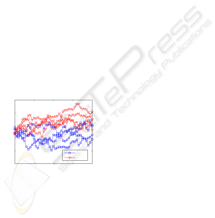
The evolution of the normalized overlap ρ
AE
be-
tween the state vectors of partner A and attacker E in
case of the geometric attack is depicted in Figure 4 as
a result of various simulations. Similar to the simple
attack, the simulations exhibit that the geometric at-
tack does not lead to synchronization even after about
40 outer rounds, while the partners synchronize after
at most 12 outer rounds.
Outer rounds
Normalized overlap ρ
N = 3
N = 4
0 10
20 30 40
0
0.2
0.4
0.6
0.8
1
Figure 4: Evolution of the normalized overlap ρ = ρ
AE
be-
tween the state vectors of partner A and attacker E during
the geometric attack derived from simulations with G =
128.
4.3 Other Attacks
A brute-force attack would require an ensemble of
2
G−1
PPMs working in parallel in order to assure its
success. This attack is not feasible when the size of
the state vector G is large. However, the idea of using
more than one network to perform an attack seems
still attractive; schemes that use an ensemble of net-
works were proposed for tree parity machines.
One of these schemes is known as majority at-
tack (Shacham et al., 2004). For this, the attacker E
uses an ensemble of M tree parity machines. When-
ever the partners update the weights as their outputs
are the same, i.e., τ
A
= τ
B
, the attacker calculates the
output bits τ
E,m
of her machines, 1 ≤ m ≤ M. If the
output bit τ
E,m
if the m-th attacking machine differs
from τ
A
, the attacker corrects one of its local fields as
in the geometric attack. Then the attacker takes the in-
ternal representations (σ
E,m
1
,σ
E,m
2
,...σ
E,m
K
), 1 ≤ m ≤
M, and selects the most common one. This majority
vote is then adopted by all attacking machines for the
application of the learning rule.
However, if this attack is performed in the same
way for permutation parity machines, then after one
outer round the state vectors of all the attacking ma-
chines become equal, because the internal representa-
tion, particularly σ
E
1
, directly defines the values that is
assigned to the state vector. Thus the majority attack
is reduced to the geometric attack after performing
one outer round.
On the other hand, the genetic attack (Klimov
et al., 2003), (Ruttor et al., 2006) is based on an evolu-
tionary algorithm instead of optimizing the prediction
of the internal representation. In the case of tree par-
ity machines, the attacker E starts with one randomly
initialized machine, but can use up to M machines.
Whenever the outputs of the partners are equal, i.e.,
τ
A
= τ
B
, the following algorithm is applied:
• Mutation step: If the attacker’s population holds
at most M/2
K−1
machines, there are 2
K−1
variants
created. These variants correspond to all 2
K−1
in-
ternal representations which reproduce the current
output τ
A
. Then the weights in the attacking ma-
chines are updated according to the learning rule
using these internal representations.
• Selection step: If the attacker’s population holds
more than M/2
K−1
machines, only the fittest ma-
chines are kept. For this, machines are discarded
from the population that predicted less thanU out-
puts τ
A
successfully (τ
A
= τ
B
) during the last V
learning steps. A limit of U = 10 and a history
of V = 20 are suggested as default values for this
step (Ruttor et al., 2006).
The situation completely changes if permutation
parity machines are used instead of tree parity ma-
chines. The effects of the learning rule in case of per-
mutation parity machines can only be observed after
one outer round, when the state vectors are updated.
However, the mutation steps are performed during the
inner rounds. Thus the state vectors are not affected
IJCCI 2009 - International Joint Conference on Computational Intelligence
500

and as a result the outputs of all the created machines
will be equal.
The efficiency of the genetic attack mostly de-
pends on the algorithm which selects the fittest ma-
chine. In the ideal case, the tree parity machine that
has the same sequence of internal representations as
A is never discarded. However, in case of permuta-
tion parity machines, it is not possible to determine
which attacking machines should be discarded and
which should be kept.
5 CONCLUSIONS
Permutation parity machines are binary variants of
tree parity machines and may be used to implement
a key-agreement mechanism based on their ability to
perform synchronization by mutual learning. More-
over, inner and outer rounds involved in the learning
rule phase make the permutation parity machines suit-
able for bit-packaging implementations accelerating
the synchronization process while keeping the secu-
rity of the protocol.
The attacks described in this paper were originally
proposed for a key exchange protocol based on tree
parity machines. In this case, the weights gradually
change by using the learning rule such that a proper
weight adaptation of the attacker’s machine during
a single iteration increases the probability of further
proper weight adaptations that eventually lead to a
successful attack.
On the other hand, in the case of permutation par-
ity machines, the output during each inner round is
produced by a different set of weights and the assign-
ment of the weights becomes a series of independent
events when G ≫ K × N. Thus a proper weight adap-
tation performed by the attacker during an inner round
barely influences the result of the following adapta-
tions and therefore the success of these kind of attacks
is unlikely.
Consequently, permutation parity machines seem
to form a viable alternative to tree parity machines in
neural cryptography.
ACKNOWLEDGEMENTS
O. M. Reyes acknowledges the support from German
Academic Exchange Service (DAAD) and Colom-
bian Institute for the Development of Science and
Technology, “Francisco Jos´e de Caldas” – Colcien-
cias.
REFERENCES
Behroozi, N. (2005). Realisierung eines Em-
bedded Systems zur Integration eines
Schl¨usselaustauschverfahrens mittels Tree Par-
ity Machines in Wireless LAN. Master’s thesis,
Hamburg University of Technology, Hamburg.
Ein-Dort, L. and Kanter, I. (1999). Confidence in prediction
by neural networks. Phys. Rev. E, 60(1):799–802.
Kanter, I., Kinzel, W., and Kanter, E. (2002). Secure ex-
change of information by synchronization of neural
networks. Europhys. Lett., 57(1):141–147.
Klimov, A., Mityaguine, A., and Shamir, A. (2003). Anal-
ysis of neural cryptography. In Zheng, Y., editor, Ad-
vances in Cryptology - ASIACRYPT 2002, pages 288–
298, Heidelberg. Springer.
Menezes, A., van Oorschot, P., and Vanstone, S. (1996).
Handbook of applied cryptography. CRC Press, Boca
Raton, FL.
Mislovaty, R., Kanter, I., and Kinzel, W. (2002). Secure
key-exchange protocol with an absence of injective
functions. Phys. Rev. E, 66:066102.
Reyes, O., Kopitzke, I., and Zimmermann, K.-H. (2009).
Permutation parity machines for neural synchroniza-
tion. J. Phys. A, 42(19):195002.
Rosen-Zvi, M., Kanter, I., and Kinzel, W. (2002a). Cryp-
tography based on neural networks - analytical results.
J. Phys. A, 35(47):L707–L713.
Rosen-Zvi, M., Klein, E., Kanter, I., and Kinzel, W.
(2002b). Mutual learning in a tree parity machine
and its application to cryptography. Phys. Rev. E,
66(6):066135.
Ruttor, A. (2006). Neural Synchronization and Cryptog-
raphy. PhD thesis, Julius-Maximilians-Universit¨at
W¨urzburg, W¨urzburg.
Ruttor, A., Kinzel, W., Kanter, I., and Nach, R. (2006).
Genetic attack on neural cryptography. Phys. Rev. E,
73(3):036121.
Schneier, B. (1996). Applied Cryptography: protocols, al-
gorithms and source code in C. Wiley, New York.
Shacham, L., Klein, E., Mislovaty, R., Kanter, I., and
Kinzel, W. (2004). Cooperating attackers in neural
cryptography. Phys. Rev. E, 69(6):066137.
Volkmer, M. and Schaumburg, A. (2004). Authenti-
cated tree parity machine key exchange. CoRR,
cs.CR/0408046.
Volkmer, M. and Wallmer, S. (2005a). Lightweight key ex-
change and stream cipher based solely on tree par-
ity machines. In ECRYPT Workshop on RFID and
Lightweight Crypto, volume July 14-15th, pages 102–
113, Graz, Austria.
Volkmer, M. and Wallmer, S. (2005b). Tree parity machine
rekeying architectures for embedded security. Cryp-
tology ePrint Archive, Report 2005(235).
Volkmer, M. and Wallner, S. (2005). Tree parity ma-
chine rekeying architectures. IEEE Trans. Comput.,
54(4):421–427.
KEY EXCHANGE PROTOCOL USING PERMUTATION PARITY MACHINES
501
