
MULTI-SEMANTIC APPROACH TOWARDS A GENERIC FORMAL
SOLVER OF TOOL PLACEMENT FOR PERCUTANEOUS SURGERY
Caroline Essert-Villard, Claire Baegert and Pascal Schreck
LSIIT - Universit
´
e de Strasbourg, Boulevard Sebastien Brant, 67412 Illkirch, France
Keywords:
Constraint solving, Surgery planning, Meta-programming.
Abstract:
In this paper, we study the multiple points of view when generalizing a method based on many criteria opti-
mization, in the framework of percutaneous surgery planning. The aim of the prototype is to find an optimal
position of surgical tools to help the surgeons in planning the intervention. We explain how, with a formal
geometric solver and meta programming, we intend to build a modular tool, capable of being extended to new
interventions, with few programming efforts.
1 INTRODUCTION
Nowadays, an increasing number of cancers are
treated by using minimally invasive techniques, such
as percutaneous radiofrequency, cryoablation, or mi-
crowave. These treatments have many advantages,
but an important drawback is that the process gener-
ally involves a difficult and tedious planning phase,
mainly relying on the study of the images of the pa-
tient (MRI, CT, ...), acquired before the intervention.
Sometimes, a secure planning can not be found, pro-
hibiting such an intervention.
In previous works, we presented a specific method
to assist the surgeon in planning percutaneous Ra-
dioFrequency Ablations (RFA) for liver tumors,
thanks to an automatic computation of an optimal
needle trajectory. We observed a lot of similarities
between the planning of this intervention and other
percutaneous procedures (cryoablation), or kinds of
surgery (e.g. Deep Brain Stimulation (DBS)).
This paper exposes how we analyzed similarities
that leaded us to a generalization of our method, us-
ing a geometric formalization of the data and a formal
geometric constraint solver. In the following section,
after a brief review of other related works in the fields
of surgery planning, we first recall our previous re-
sults. Then, we expose our analysis of the framework
and explain our approach to extend the solver, and ex-
plain our choice of meta programming.
2 RELATED WORKS
In the domain of assistance to surgery planning,
among which percutaneous interventions, various
tools already exist. Most of them are simulators, mod-
elling what will be the effect of a treatment, for a
given placement of tools proposed by the surgeon.
However, this forces the surgeon to perform him-
self/herself the trial and error search. Other authors
proposed interesting attempts of automatic methods,
but they have important drawbacks. In (Altrogge
et al., 2006), authors do not take into account the pres-
ence of surrounding organs. Authors of (Lung et al.,
2004) and (Adhami and Coste-Mani
`
ere, 2003) con-
fess a long computation time, and the first one algo-
rithm is only in 2D. In (Brunenberg et al., 2007), au-
thors restrict the research to a limited set of possible
entry points, avoiding possibly good trajectories to be
discovered. To our knowledge, very few automatic
methods exist, and they are all very specific to one
type of intervention. In this study, we focus on the
genericity of the solving process for a set of percuta-
neous interventions sharing a lot of similarities.
In previous papers (Baegert et al., 2007a; Baegert
et al., 2007b), we explained our method for provid-
ing automatically an optimal needle placement, in the
framework of percutaneous RFA preoperative plan-
ning. The rules governing these interventions are col-
lected from literature, observations, discussions with
experimented surgeons. They are implemented in the
program as functions, and solved using the patients
443
Essert-Villard C., Baegert C. and Schreck P. (2009).
MULTI-SEMANTIC APPROACH TOWARDS A GENERIC FORMAL SOLVER OF TOOL PLACEMENT FOR PERCUTANEOUS SURGERY.
In Proceedings of the International Conference on Knowledge Engineering and Ontology Development, pages 443-446
DOI: 10.5220/0002303804430446
Copyright
c
SciTePress
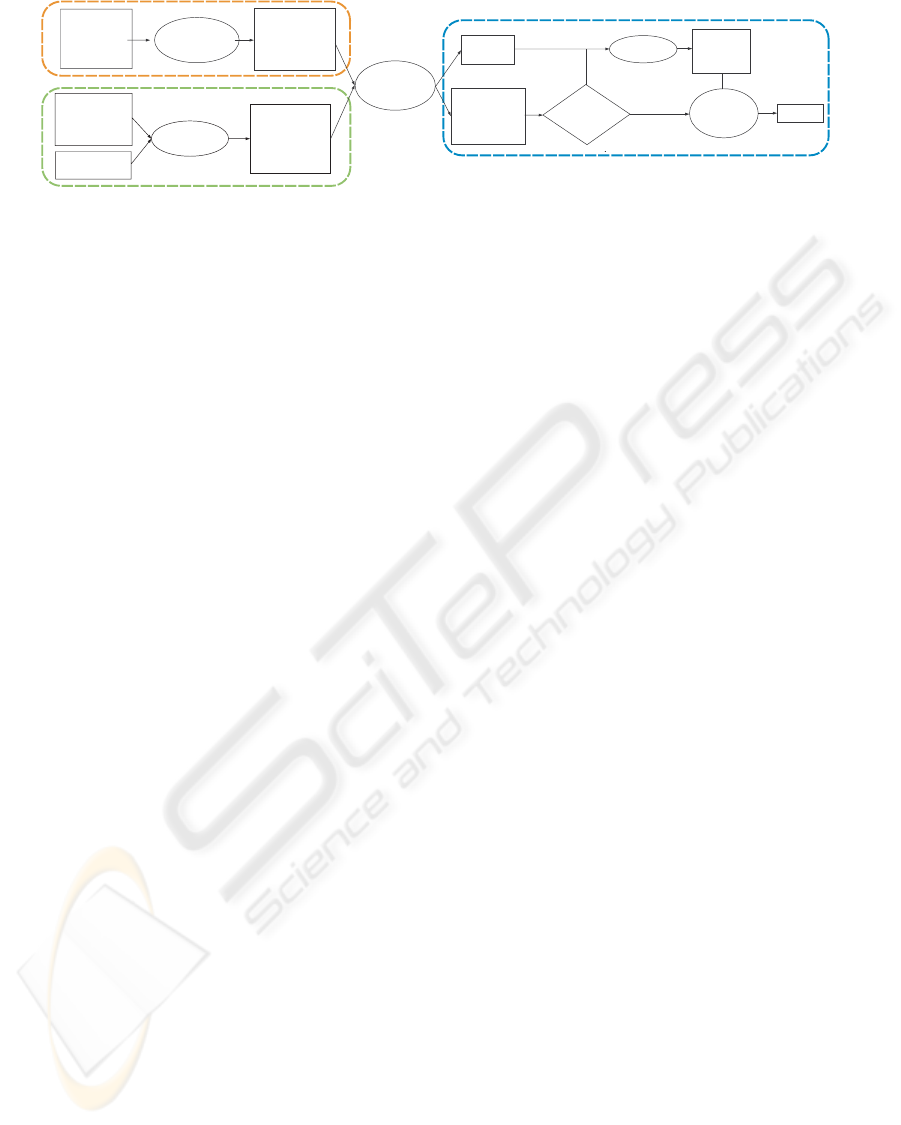
Intervention
Technique
(Literature,Surgeon's
Expertise,Case Studies)
Set of
Geometric and
Mathematic
Rules
(constraints)
Formalization
Devices
Specifications
Patient
Images
(MRI, CT, ...)
Patient Data
(3D
reconstructed
structures)
3D
Reconstruction
Solution
Space
Optimal
Solution
(automatically
proposed)
Proposed
Solution
is OK
Navigation
Validation
of
Solution
Optimal
Solution
(manual)
no
yes
Solution
Geometric
Constraint
Solving
Patients data
Interventions data
Solution treatment
Figure 1: Process diagram.
images as input data. “Avoiding vital structures”, and
“minimizing the damages on healthy cells” are exam-
ples of rules that are translated into “eliminating solu-
tions crossing any organ mesh”, and “choosing those
minimizing the volume of the effect of the treatment”.
The output is a solution space constituted by the set
of possible solutions, and an optimal solution among
them. In Fig.1, a diagram showing the overall work-
flow is shown. The data specific to a type of interven-
tion is defined once for all for a type of intervention,
and is currently included in the code of the solver.
3 PERCUTANEOUS
INTERVENTIONS
3.1 Motivation
Our previous method and the associated software
were designed for a specific kind of intervention. The
only modifiable parameters were the weighting coef-
ficients applied to the different constraints. We aim
at generalizing our approach, in order to be able to
easily take into account: new constraints, new kinds
of interventions, according to the different points of
views of the actors of the process.
3.2 Different Points of View
In this field of application, we have to keep in mind
that the final user as well as the main expertise con-
tributor is a surgeon who is not necessarily a specialist
in computer programming. So the description of the
rules of the intervention, and the visualization, have
to be adapted to the surgeon’s vocabulary and habits.
Another point of view is the solver’s one: we have to
provide our solver with a language and some data it
is able to understand. A third point of view concerns
the visualization. The computer needs useful under-
standable information for a proper display. Therefore,
various points of view coexist, and it is necessary that
the application deals with them.
3.3 Analysis of Knowledge
Many procedures involving the placement of one or
more tools that can be assimilated to rays, with the
aim of reaching and treating a target, have a lot of
common points in their planning procedures. The
two main similarities are the definitions of what
constitutes a tool and what is a solution. We will
illustrate our explanations with different examples:
placement of needles for RFA and cryoablation, and
DBS electrodes.
Definition. A tool is defined by 3 features: its
geometrical shape, the geometrical shape of the effect
it produces, and the relative placement of the shape
of the effect according to the shape of its support.
For instance the cryoablation’s tool is a needle, its
effect is ellipsoidal and is centered at the location of
the decompression chamber. All other information on
the tool can be deduced from these 3 data.
The expert describes the tool with a specific
terminology, for example “needle”, “electrode”, etc.,
and is able to make an approximative description of
the effect. He can use either a geometric vocabulary
like “cylindric shape, with a length of 5mm and
a section of 3mm”, or a more fuzzy vocabulary
such as “the effect looks like an olive”. The solver
and the visualization module need a more concrete
description of the tool and its effect, such as sets
of voxels or meshes. Therefore all the information
about the tool have to be collected, or deduced one
from the other in any way.
Definition. A solution is a placement of a tool. A
placement is composed of a direction (2 degrees of
freedom (DOF)), an origin (3 DOF), and an extra
value, for instance the intensity of the effect (1 DOF).
KEOD 2009 - International Conference on Knowledge Engineering and Ontology Development
444

Table 1: Examples of complex operators, with comprehensive names, and their profiles.
lengthOfTool: tool → float distToolOrgan: tool * solution * shape → float
volumeOfEffect: tool * solution → float distEffectOrgan: tool * solution * shape → float
centerOfGravity: shape → point coverZoneOrgan: tool * solution * shape → bool
dist2Pts: point * point → float toolInsertionPoint: shape * solution → point
Table 2: Our current geometric universe.
Types Examples
point insertion point, intersection organ/tool
shape organ, zone of effect
tool electrode, needle
solution possible solution, optimal solution
For RFA, a solution is a position of the tip of a nee-
dle, a direction of the main axis of the needle, and the
power sent by the generator (size of the effect).
Here again, we have various points of view. The
application (solver and visualization) works with 3D
Cartesian coordinates, whereas the surgeon deals with
various other position references: an insertion point
on the skin, or another coordinate system such as Lek-
sell coordinates in neurosurgery.
Another common point is that all the constraints
we consider are based on the same constants: the im-
ages of the patient, that are segmented providing a set
of organs (3D masks and meshes).
4 GEOMETRIC UNIVERSE
The meta programming approach we chose to use in-
cludes a geometric universe, and operators that can
be combined to define the geometric constraints rep-
resenting the rules of the surgical intervention.
4.1 Types
As a geometric universe, apart from usual types such
as integers, floating numbers and booleans, we also
use composed types, as we describe in Table 2. Those
types are used for our constants and unknowns in the
construction of our constraints.
Those composed types allow us to include for
each entity all necessary information for the differ-
ent points of view, and the different uses. For exam-
ple, the “shape” type includes a 3D voxel mask (seg-
mented from CT or MRI images) and a 3D mesh (re-
construction from a mask (organs), or by simple syn-
thesis (effect)). Other properties such as the volume
of a shape, can be deduced from these ones.
4.2 Operators
The differences between each surgical intervention
are the values we give for the elements that define
a tool, and the constraints to be solved. These con-
straints are expressed under the form of a combination
of (predefined) operators, constants, and unknowns.
We currently use very basic operators (such as plus,
minus, multiply, and, or, etc.) as well as complex op-
erators like the ones shown on Table 1. The terms
that are formed using those operators and the con-
stants can directly be written in the XML file describ-
ing the surgical intervention, that can be read by the
interpreter.
5 APPLICATION TO
RADIOFREQUENCY
PLANNING
Our methodology for RFA planning explained in
(Baegert et al., 2007a; Baegert et al., 2007b) was orig-
inally implemented in a specific solver. In order to
validate our new approach, we transformed our orig-
inal solver into a new generic solver, extracting the
specific functions and replacing them by generic op-
erators. The solver takes as an input trees of oper-
ators representing constraints, and performs a depth-
first solving of the operators. We wrote the constraints
using an XML syntax in a file dedicated to RFA inter-
ventions. An example of XML constraint is written
in Table 3. In this example, the term constrains the
trajectory (distance from insertion point to target) to
be shorter than the length of the needle.
Finally, we experimented the solver to compare
the solutions. The generic solver was tested on 10
patients cases we had already solved with the original
version, and that were already validated by an expert
(see (Baegert et al., 2007a) for detailed results). The
resolution consists in finding the optimal position for
the RFA needle, given a 3D scene representing the
patient’s anatomy, and given the constraints file for
RFA interventions.
As expected, for each tested patient case, the re-
sults are identical in terms of precision of the solu-
tion (identical positions of tool and sizes of effect).
MULTI-SEMANTIC APPROACH TOWARDS A GENERIC FORMAL SOLVER OF TOOL PLACEMENT FOR
PERCUTANEOUS SURGERY
445

Table 3: Example of XML constraint, for Percutaneous RFA treatment.
<strict constraint name=”needle length restriction”>
lower(dist2Pts(centerOfGravity(target), toolInsertionPoint(skin, solution)), lengthOfTool(tool))
</strict constraint>
The reason is that the whole computation operation
used in the solver did not change, we only splitted the
functions into small operators which combination de-
scribed in the XML constraints file recreates the same
computation scheme. The only difference in the re-
sults is in terms of computation time, that is a little
bit slower with the generic version. We also expected
this result, as an gain in genericity often comes with a
performance loss. However, given that in both cases
the total computation time of this planning process is
performed in an average time of a few seconds (maxi-
mum experimental time for the worst case 2mn.), this
increase in the computation time was considered as
negligible and perfectly acceptable by the surgeons.
6 FUTURE REQUIREMENTS FOR
MODULARITY
We presently dispose of a tested generic solver, di-
rectly able to find an optimal placement planning for
RFA, but also for other percutaneous interventions
with very similar tools and processes, if the appropri-
ate constraint file is written. We are currently working
on the constraint file for DBS in neurosurgery, with
appropriate validation by experts.
For a more open genericity, we also need in future
works to make sure of more extensions capabilities, in
order to be able to include more surgical interventions
types. We defined 3 categories of extensions, imply-
ing 5 different stages of various level of difficulty in
the improvement of modularity of our method: new
constraints using new operators, similar interventions
using more than one needle (e.g. cryoablations), and
interventions having other shapes of effect (e.g. ra-
diotherapy).
7 CONCLUSIONS AND FUTURE
WORKS
We described how we abstracted an existing solver
of geometric constraints aiming at computing auto-
matically an optimal placement of surgical tools for a
specific intervention, to obtain a generic solver. We
implemented a system loading a file describing the
constraints of the surgical intervention for which a
planning is required. The use of meta-programming
allows us to describe the geometric constraints rep-
resenting the rules of the surgical intervention with
a language more accessible than a programming lan-
guage, and with a geometric universe and operators
that could be redefined on the fly in the future.
Further works remain to be done in order to be
even more generic and to extend to more surgical
interventions. This study showed us that it will be
feasible in a reasonable time, and with a reasonable
amount of work. Besides the future extensions of the
solver, we will also have to write the constraints of the
other aimed surgical interventions, and validate them
with experts.
REFERENCES
Adhami, L. and Coste-Mani
`
ere, E. (2003). Optimal plan-
ning for minimally invasive surgical robots. IEEE
Transactions on Robotics and Automation : Special
Issue on Medical Robotics, 19(5):854–863.
Altrogge, I., Kr
¨
oger, T., Preusser, T., B
¨
uskens, C., Pereira,
P., Schmidt, D., Weihusen, A., and Peitgen, H. (2006).
Towards optimization of probe placement for radio-
frequency ablation. In MICCAI’2006, volume 4190
of LNCS, pages 486–493.
Baegert, C., Villard, C., Schreck, P., and Soler, L. (2007a).
Multi-criteria trajectory planning for hepatic radiofre-
quency ablation. In MICCAI’2007, volume 4791 of
LNCS, pages 584–592.
Baegert, C., Villard, C., Schreck, P., and Soler, L. (2007b).
Trajectory optimization for the planning of percuta-
neous radiofrequeny ablation on hepatic tumors. Com-
puter Aided Surgery.
Brunenberg, E., Vilanova, A., Visser-Vandewalle, V.,
Temel, Y., Ackermans, L., Platel, B., and ter
Haar Romeny, B. (2007). Automatic trajectory plan-
ning for deep brain stimulation: A feasibility study.
In MICCAI’2007, volume 4791 of LNCS, pages 584–
592.
Lung, D., Stahovich, T., and Rabin, Y. (2004). Comput-
erized planning for multiprobe cryosurgery using a
force-field analogy. Computer Methods in Biome-
chanics and Biomedical Engineering, 7(2):101–110.
KEOD 2009 - International Conference on Knowledge Engineering and Ontology Development
446
