POSITION/FORCE CONTROL OF A 1-DOF SET-UP POWERED
BY PNEUMATIC MUSCLES
Aron Pujana-Arrese, Kepa Bastegieta, Anjel Mendizabal, Ramon Prestamero and Joseba Landaluze
IKERLAN Research Centre, Arizmendiarrieta 2, E-20500 Arrasate (The Basque Country), Spain
Keywords: Pneumatic muscle, Robotic Arm, Position/Force Control, Hybrid Control, Impedance control.
Abstract: A one-degree-of-freedom set-up driven by pneumatic muscles was designed and built in order to research
the applicability of pneumatic artificial muscles in industrial applications, especially in wearable robots such
as exoskeletons. The experimental set-up is very non-linear and very difficult to control properly. This paper
describes the control of this mechatronic system’s interaction with its environment, controlling both its
position and the force exerted against it. The classic position/force control techniques - hybrid control and
impedance control - have been adapted to pneumatic muscles and applied to the experimental set-up
developed. An alternative solution is also proposed whereby force or torque control is based on the
calculation made by an estimator instead of on direct measurement by a sensor. The article presents a
detailed analysis of the force and torque estimator used to close the control loops in the two position/force
control schemes. Finally, the article concludes by presenting the experimental results obtained and the most
outstanding conclusions of the study as a whole.
1 INTRODUCTION
The group of researchers from the IKERLAN
technology centre working on the development of
mechatronic systems have been involved for the last
three years in the design and construction of an
upper limb IAD (Intelligent Assist Device)
(Martinez, 2007; Martinez, 2008). More specifically,
the device is an exoskeleton for helping the user
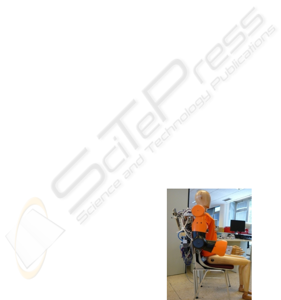
carry out routine tasks in the workplace (Figure 1).
One of the requirements established from the start
was to include non-conventional actuators as far as
possible. Among the alternatives studied, artificial
pneumatic muscles were considered to be the most
suitable forms of actuation. In order to study the
applicability of this type of actuators in
biomechatronic systems a 1-DoF experimental set-
up was built, driven by a pair of antagonistic
pneumatic muscles. Initially, a dynamic model of the
pneumatic muscle was created, and then used to
make the full model of the experimental set-up. This
model was experimentally validated (Pujana-Arrese,
2007).
Motivated by the high degree of non-linearity of
the experimental prototype, the authors developed
different solutions for robust control of the system’s
angular position: from a first initial attempt using
basic controllers, to more advanced techniques
achieved such as H
∞
or the non-linear sliding mode
technique (Pujana-Arrese, 2008; Arenas, 2008).
This paper takes a step further as regards control
of the mechatronic system’s interaction with its
environment, controlling not only the position but
also the force exerted against it. An alternative
Figure 1: Exoskeleton ÎKO (IKerlan’s Orthosis) worn by a
dummy.
228
Pujana-Arrese A., Bastegieta K., Mendizabal A., Prestamero R. and Landaluze J. (2009).
POSITION/FORCE CONTROL OF A 1-DOF SET-UP POWERED BY PNEUMATIC MUSCLES.
In Proceedings of the 6th International Conference on Informatics in Control, Automation and Robotics - Robotics and Automation, pages 228-237
DOI: 10.5220/0002208902280237
Copyright
c
SciTePress
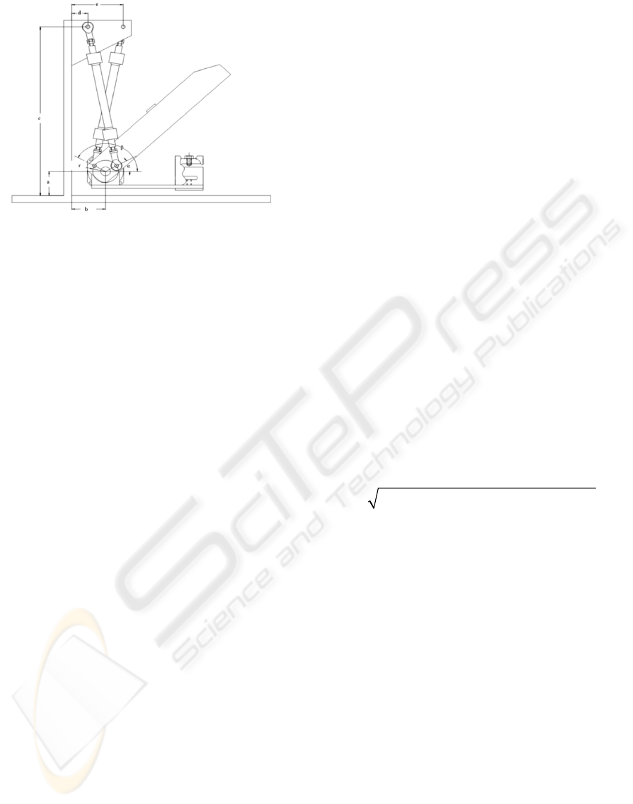
Figure 2: Geometric model of the 1-DoF robotic arm.
solution is also put forward whereby the force or
torque control is based on the calculation made by
an estimator instead of on direct measurement by a
sensor.
A classic, in the field of the position/force
control, is the Hybrid Controller strategy put
forward by Raibert and Craig (1981). The controller
carries out its action using selection matrixes which
establish some spatial directions where position
control must be carried out and some others where
force must be controlled. In this way the force and
position control actions are uncoupled by using the
appropriate treatment of the spatial geometry where
the manipulation task is being carried out. Another
classic strategy is Impedance Control (Hogan,
1985), which does not control the position or the
force but the dynamic relation between the two. This
type of control strategy is deemed to be very suitable
for IADs, although it needs to be adapted depending
on the specific application.
The object of this paper is to present the
algorithms implemented for controlling interaction
with the environment, stressing the fact that an
estimator requiring no direct measurement of either
the torque or the force exerted by the mechatronic
device has been developed for this purpose. The first
point contains a brief description of the experimental
set-up used for this study, and the paper then goes on
to present a theoretical review of the control
techniques most commonly used for these ends:
Hybrid Control and Impedance Control. There then
follows an in-depth analysis of the force and torque
estimator used to close the control loops in both
cases, and there is then a detailed description of the
control diagram used for both the Hybrid Control
and Impedance Control. Finally, the article
concludes by presenting the experimental results
obtained, and the most outstanding conclusions of
the study as a whole.
2 SET-UP DESCRIPTION
A human arm orthosis-type application has been
taken into consideration when designing the set-up.
To this end and albeit with a single degree of
freedom, it was considered that it should allow for
the greatest angular displacement possible, and that
it should be able to transport the greatest mass
possible at the tip (emulating a weight borne by the
hand). On the other hand, however, it needed to be
confined to the length of the pneumatic muscles. In
seeking a compromise between all the specifications,
a displacement of around 60º and a maximum mass
to be moved at the tip of 8 kg were set. By trying to
minimize the length of the muscle required, the
design focused on the mechanism that would enable
the arm and inertias to rotate with good dynamics by
means of the two muscles.
The pneumatic muscle that was chosen was the
DMSP-20-200N manufactured by Festo. Figure 2
and Figure 3 show the resultant mechanism and a
picture of the prototype. The parameter values that
define the mechanism are:
a=5 mm; b=85 mm; c=491 mm; d=40.6 mm
e=129.4 mm;
α
=0º-60º;
β
=120º-180º; r=32 mm
From these values the distance L (mm) between
the ends (joining points of the mechanism) of the
pneumatic muscles is:
175059 2841.6 cos 26624 sinL
αβ
=+⋅−⋅
When the muscles are without pressure, the
distance L is of 423 mm, with the length of the
muscle fibre being 200 mm. The centre of the arm
mass with regard to the centre of rotation is at a
height of 17.6 mm and at a horizontal distance of
205 mm, considering that the arm is in the horizontal
position. The arm mass is 0.987 kg. The centre of
the additional masses placed on the end of the arm
would be at a height of –24 mm and at a horizontal
length of 367 mm with regard to the centre of
rotation, always bearing in mind that the arm is in
the horizontal position. The set-up may be rotated so
that the arm moves in a horizontal plane and the
effects of gravity are therefore cancelled out. The
prototype (Figure 3) includes a FAGOR S-D90
encoder, which supplies 180,000 pulses per turn, and
a load cell on the lower stop of the model.
The schematic diagram of the set-up, which
includes the control hardware, sensors and
pneumatic circuit, is shown in Figure 4. As the
figure shows, two Festo MPYE-5-1/8HF pneumatic
servo-valve are used for actuation, each linked to
POSITION/FORCE CONTROL OF A 1-DOF SET-UP POWERED BY PNEUMATIC MUSCLES
229
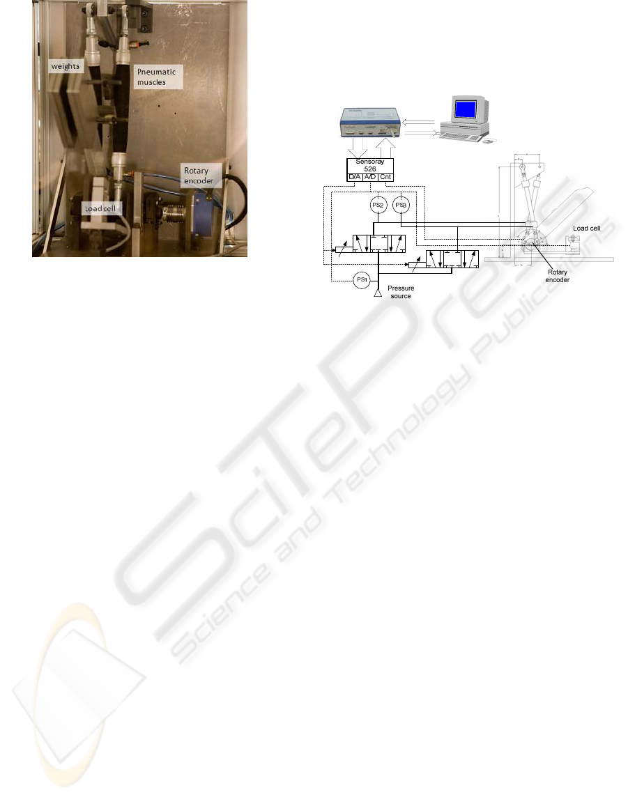
Figure 3: Picture of the experimental set-up.
one pneumatic muscle and controlled independently
by the controller. The controller hardware is PIP8,
an industrial PC made by the company MPL, which
is very similar to The MathWorks’ xPCTargetBox.
A PC104 card (Sensoray model 526) was
incorporated into the PIP8 in order to read and write
all the system signals. Control algorithms were
implemented in Simulink and code was generated
and downloaded in the aforementioned hardware by
means of two of The MathWorks’ tools: RTW and
xPCTarget.
3 POSITION/FORCE CONTROL
ALGORITHMS OVERVIEW
Research into pneumatic muscles has been carried
out considering them as orthosis actuators. And an
orthosis, or exoskeleton, is a wearable robotic
device. In an initial approach, the basic control of an
orthosis-type device can be considered to be based
on position control, where the user creates the
movement set-point and closes the loop aided by the
human body’s own sensors. Detecting the user’s
intention and creating the movement set-point on the
basis of this is a key element. Another very
important factor to be taken into account is the
interaction with the environment, whether from the
perspective of controlling the force exerted so as not
to cause damage to persons within the robotic
device’s field of action, or because the device is
being used as a force augmentation system. From
this point of view, its functioning is similar to that of
a robotic manipulator. There are two classic
position/force schemes for robotic manipulators:
hybrid control and impedance (or admittance)
control. These schemes have been considered valid
for the case of an arm orthosis, although they have
some special characteristics that must be taken into
account when the actuators are pneumatic muscles.
Figure 4: Schematic diagram of the set-up and pneumatic
circuit.
3.1 Hybrid Position/Force Control
Hybrid control is a conceptually simple method for
controlling both the position and the contact force
generated at the tip of a manipulator during a task
involving restricted movement. The method does not
specify any feedback control law for regulating the
errors, but rather a control architecture in which any
position and force control techniques can be
considered. The principle of hybrid control is based
on the idea that each manipulation task can be
described by specifying a set of contact surfaces.
These surfaces serve to detail the restrictions
existing in the system, which may be either natural
or artificial.
The natural restrictions are connected with the
system’s particular mechanical and geometrical
characteristics. Artificial restrictions, on the other
hand, are connected with the control task objectives,
and are specified in terms of position or force
parameters.
Natural and artificial restrictions are defined
within the space of the task, not within the space of
the actuations. One natural and one artificial
restriction may be specified for each degree of
freedom of the task. In general, taking the task
geometry into account, it is not difficult to determine
the natural restrictions existing and decide on the
most suitable way of dividing the space of the task
on the basis of these.
For the case of an orthosis, normally mixed
exercises are performed, which consist of both
ICINCO 2009 - 6th International Conference on Informatics in Control, Automation and Robotics
230

Figure 5: Structure of the hybrid position/force controller.
stages of free movement and stages of restricted
movement. The restricted movement part can be of
much less importance than in the case of a robotic
manipulator, any may simply consist of a force
control loop, which does not necessarily have to act
at the same time as the position control in other
directions. In any case, a supervisor, able to switch
between the different configurations of the
manipulator and the corresponding control laws, is a
key element. A supervisor of this type must pay
special attention to the impact between the
manipulator and the environment, and to its
separation.
Figure 5 shows a diagram of position/force
hybrid control valid for both an orthosis and the 1-
DOF set-up used to analyse the specific case of the
pneumatic muscles. It basically consists of two
independent controls, one for position and the other
for force, and a supervisor that switches between one
control type and another depending on the contact
with the environment. The supervision is based on
the information on the force exerted, which may be
provided by a force sensor or an estimator. The
supervisor, at the same time as the set-point
generator, makes the transition between the
controllers in a soft manner, to prevent rebounds and
to assure the system’s stability.
As already mentioned, the hybrid control scheme
does not impose the control techniques that are used
for the position controller and for the force
controller.
3.2 Impedance Control
Impedance control is another classic force control
scheme, and it is of great interest in the case of
orthoses. It does not require a supervisor and it is
able to take on the control of a composite task, with
free and restricted movement stages, maintaining the
system’s stability without changing the control
algorithm. It is based on the idea of controlling the
dynamic relationship between the force and position
ORTHOSIS
Kinematic
transformation
J
t
Senso
r
K
f
τ
θ
θ
X
F
int
X
e
·
+
_
+
_
Inertial, gravitational
and friction effects
J
-1
K
p
K
v
δ
X
X
D
+
_
+
_
V
D
+
+
J
δ
V
_
+
Environment
position
Stiffness
Figure 6: Structure of the impedance controller.
variables of the physical systems. It is presumed that
in any manipulation task the environment contains
inertias and kinematical restrictions, i.e. systems
accepting forces as input and responding by means
of displacements (admittances). The manipulator in
contact with the environment must accordingly
behave as an impedance and respond with a
determined force to the displacement of the
environment. The general strategy may be
established in terms of controlling a movement
variable and at the same time providing the
manipulator with a disturbance response in the form
of impedance. Thus, the interaction between the
manipulator and its environment can be modulated
and controlled by acting on the impedance values.
In impedance control, the functional form of the
torque of a manipulator’s actuators is well-known:
where each line of the second member represents a
contribution of a different nature to the total torque.
The first line corresponds to terms dependent on the
position, the second to terms of speed, the third to
terms of force, and the fourth to terms of inertial
coupling. Within the field of the actuations, this
equation expresses the behaviour that the controller
should be able to induce in the manipulator, in the
form of a non-linear impedance. The input variables
are the desired Cartesian positions and speeds, and
the terms – linear or not – that specify the required
dynamic behaviour, characterised by the magnitudes
M, B, and K. Figure 6 shows the typical impedance
control structure for a robotic manipulator or for an
orthosis, in which the feedback gains of the position,
speed and force loops, K
p
, K
v
and K
f
respectively,
depend on the reference inertia and mass tensors and
on the values designed for stiffness, K, and damping,
B, and they are deduced from the control law (1).
[]
11
act 0
11 1
0
11 t
int int
1
() () () ()
()J () () ()
() () ()
() () (, ) (, )
IJ MKXL S
IMBVJ V
IJ MF J F
IJ G C
τθθ θθ
θθ θω ω
θθ θ
θθθω θω
−−
−− −
−−
−
=−
⎡⎤
+−
⎣⎦
+−
++
+
+
(1)
POSITION/FORCE CONTROL OF A 1-DOF SET-UP POWERED BY PNEUMATIC MUSCLES
231

The force feedback F
int
, based on a measured
force or estimated force, has the effect of changing
the apparent inertia of the manipulator. However, the
impedance control scheme can also be applied
without a sensor or force estimator. In this case the
force is not explicitly controlled, but, depending on
the impedance values used in the controller design,
the force the system exerts on the environment is
limited.
4 TORQUE/FORCE ESTIMATOR
As already mentioned in the introduction, on most
occasions different sensors are used to directly
measure the force or torque exerted by the actuators
in order to control the interaction between the
mechatronic system and its environment
(Tsagarakis, 2007; Jia-Fan, 2008).
This paper puts forward the idea of carrying out
the control of the interaction between a mechatronic
system driven by pneumatic muscles and its
environment without any direct measurement at all
of either the torque exerted by the pneumatic
actuators or the force exerted by the arm. The torque
and force are calculated on an estimated basis from
the angular position of the arm and the pressures on
the pair of muscles, as set out in the ensuing
paragraphs.
The force exerted by each muscle can be
modelled on the basis of its contraction and interior
pressure according to equation (2) (Pujana-Arrese,
2007).
/
·
/
·
/
/
/
(2)
w here
··
·
·
(3)
q is the contraction of each muscle (up and down), P
is the pressure exerted on each muscle, and the
parameters D
1
, D
2
, D
3
, a, b, c, d and e are constants
obtained from empirical tests for characterising the
behaviour of the muscles (Pujana-Arrese, 2007).
To calculate muscle contraction, trigonometric
formulas are used to relate this contraction with the
angle formed between the arm and the vertical
(Figure 2). The torque exerted by the combination of
the two pneumatic muscles
can thus be
deduced as:
··sin
2
2
·
·sin
2
2
(4)
where F
up
is the force exerted by one pneumatic
muscle, F
down
is the force exerted by the other
pneumatic muscle, and r is the distance between the
rotation point and the lower joining points of the
pneumatic muscles. The angle of the arm with
respect to the vertical is designated as θ, while θ
top
and θ
down
are the angles corresponding to the
physical limit stops of the prototype. α
up
is the angle
formed with respect to the horizontal by the muscle
designated as up, while α
down
is the angle formed by
the other muscle with respect to the horizontal.
Despite the good results obtained on simulation,
the experimental tests showed lack of accuracy of
the estimated value with regard to the torque
actually exerted by the muscles. The main reason for
this is that equation (2) does not contemplate
hysteresis, which is a feature of the pneumatic
muscles. The error assumed on ignoring the effects
of hysteresis means the estimator is not applicable in
cases where the arm moves freely. However, when
the arm is blocked by collision, the pressures, and
consequently the torque, increase in such a way that
the measurement error is not critical.
In order to obtain an estimator that behaves
correctly for free movement, with the system
moving at low torque values, a development based
on Newton’s laws of motion is proposed. This new
estimator calculates the torque by means of equation
(5), which is in fact the development of Newton’s
sec nd lao w of motion.
··
·
sin
.
··
·sin
·
(5)
where m is the mass of the arm, L the distance
between the rotation point and the arm’s centre of
gravity, θ the angle between the arm and the vertical,
β the angle between the rotation point and the centre
of gravity, and I
o
its inertia on the rotation point. N is
the number of extra masses placed on the tip, and m
p
is the weight of each mass (N⋅m
p
thus represents the
mass placed at the tip of the arm).
This torque estimator functions correctly but has
two negative aspects. The first is that if the structure
has two or more degrees of freedom instead of one,
calculating the equation becomes rather
complicated. The other aspect is that if any kind of
interaction is produced with the environment, e.g. a
collision, when the arm movement is blocked
ICINCO 2009 - 6th International Conference on Informatics in Control, Automation and Robotics
232

equation (5) is no longer of use for estimating the
torque exerted by the actuators.
Knowing that the torque estimator based on
Newton’s law of motion calculates the torque
correctly in the case of free movement, and that the
moment evaluated by the torque estimator based on
the muscle pressures can be acceptable when an
interaction occurs with the environment, it was
decided to create a hybrid torque estimator. This
hybrid estimator requires some kind of observer to
indicate whether an interaction with the environment
has occurred, so that the desired estimator can be
selected at each time. In short, when free movements
are made the estimator used will be the one based on
Newton’s laws (
), and in the case of limited
movements or interactions with the environment the
estimator used will be the one based on the pressures
of each muscle (
), switching between them
where necessary.
The switch between the torque estimator and the
force estimator is practically instantaneous: all that
is needed is to apply ation (6): next equ
Where
is equal to
in the case of no
interaction with the environment, or equal to
if
there is a collision. l is the distance between the
rotation point and the tip of the arm on which the
force is to be calculated.
(6)
5 HYBRID POSITION/FORCE
CONTROL OF THE SET-UP
Figure 5 shows a diagram of the Hybrid Control
implemented. It basically consists of a supervisor
block that switches between position control and
force control according to the status of the
interaction between the arm and its environment (in
this case, the lower limit stop). The position control
is thus carried out separately from the force control,
i.e. the system is controlled by the position
algorithm until the supervisor block detects that a
collision has occurred. When this happens, it
switches between the controls as soft as possible,
activating the force control.
5.1 Position Control Algorithm
The hybrid control structure enables different,
independent algorithms to be implemented for
position and force control. In the last few years the
Figure 7: Diagram of the internal pressure loops based
position control algorithm.
authors have conducted research into the position
control of this same experimental device.
Owing to the fact that the results obtained with a
classical PI controller were not good, due to its high
non-linearity, other advanced control techniques
were applied in order to correctly control the angular
position. Firstly, a PID-based controller was
enhanced with linear and non-linear internal loops.
However, good performance requires the use of
robust or non-linear control techniques (Thanh,
2006; Balasubramanian, 2007) and in this context,
the application of different control techniques is
found in the literature. Therefore, a robust linear
control technique H
∞
(Pujana-Arrese, 2008), and a
robust non-linear technique, sliding-mode (Arenas,
2008), were applied.
Subsequently, based on an idea applied by
Tsagarakis and Caldwell (2007), a new position
controller was developed based on an internal
pressure loop for each muscle. This new position
algorithm requires the use of one servo-valve for
each pneumatic muscle instead of one single valve
for each DoF, as used with the position algorithms
that were designed and implemented previously.
Although this new solution initially doubles the
variables that have to be controlled for each degree
of freedom, it can be considered as a single-variable
approach for each joint. Based on the symmetrical
co-contraction of the opposing muscles, an
asymmetrical variation is set in the pressure of each
muscle. Thus, based on an initial pressure (P
0
) the
setting is increased in one of the muscles and
redu ed b nt ( ther. c y the same amou ΔP) in the o
∆;
∆
(7)
Accordingly, from the control point of view, the
position control problem is still SISO with the
angular position of the joint (θ) as the output and the
pressure variation (ΔP) as the input.
Figure 7 shows the position control schematic
based on the internal loops that control the pressure
POSITION/FORCE CONTROL OF A 1-DOF SET-UP POWERED BY PNEUMATIC MUSCLES
233

Table 1: Force PID parameters for the different impact
points.
64.8º 48.2º 37.5 27.2º
K
p
0.045 0.025 0.03 0.025
K
i
0.05 0.05 0.03 0.04
K
d
0.002 0.0002 0.001 0.0005
in each muscle, implemented by means of PI
algorithms. As it has been already mentioned, the
pressure set-point for each controller is set on the
basis of an initial value (P
0
), adding and subtracting
the same quantity (ΔP). The value of this
increase/reduction is the output of the most external
loop of the controller (the position loop). This loop
has also been implemented by means of a PID
algorithm. The gains of both pressure loops were
adjusted to the values K
p
=4, K
i
=4, and the gains of
the position loop to K
p
=0.21, K
i
=1.2, K
d
=0.04, being
P
0
=3 bar.
The experimental results for the hybrid
position/force control shown later in this paper were
obtained with the position algorithm based on the
internal pressure loops tuned for a nominal load of 3
Kg placed at the tip.
5.2 Force Control Algorithm
Whereas direct measurement with the encoder
located on the axis is the procedure used for position
control, the value calculated by the force estimator is
used to close the force control loop. The reaction of
the device to any impact can thus be controlled
without requiring the use of a sensor at the exact
point of collision.
Unlike the case with position control, simulation-
based tests confirm that to control the force correctly
it is not necessary to design such complex
algorithms. Also, the specifications of orthosis-type
devices are much more restrictive for position
control than they are for force control, in which it is
normally sufficient for the force to be limited in the
case of an inopportune collision.
The algorithm implemented is simply a PID
tuned for a nominal load of 3 Kg. In any case, due to
the non-linearity of the system, the response varies
depending on the angular position in which
switching between position control and force control
occurs. With the aim of obtaining a more uniform
response, four points distributed over the whole
range of movement of the metal arm were selected.
These five points divide the movement of the system
into five different zones. By means of impacts
applied to these points, four different PID algorithms
were tuned. Finally, a gain scheduling type strategy
was implemented, which linearly combines the
outputs of the two PIDs delimiting the zone in which
the collision occurs.
Table 1 shows the PID algorithm parameter
values for each of the points expressed according to
their angular situation with respect to the vertical
plane.
6 IMPEDANCE CONTROL OF
THE SET-UP
The classic impedance control formulation is based
on the hypothesis that the actuation system is able to
supply the torque required by the control algorithm,
i.e. the impedance control output is the torque set-
point for the actuator. This hypothesis is not so
evident in the case of one degree of freedom
actuated by means of an antagonistic pair of
pneumatic muscles. Tsagarakis (2007) puts forward
the same algorithm based on the independent
pressure loops used for controlling the angular
position, which, as can be observed in Figure 7, is
the one that has been implemented. As explained
above, the scheme has two separate PI controllers
for controlling the internal pressure of each muscle
and an external loop governed by a PID, which in
this case serves to close the torque loop. Logically,
the tuning of the pressure loops is the same as in the
case of the position control, i.e. K
p
=4, K
i
=4, while
the optimum values for the torque loop gains are
K
p
=0.12, K
i
=0.6, K
d
=0.0024.
The impedance control strictly speaking was
implemented by adapting the general control law (1)
to the experimental prototype presented in this
study. The first step was to obtain a dynamic model
of the system. In the field of robotics there are
several methodologies for system modelling
(including those of Newton-Euler and Lagrange-
Euler), but in this case, given the mechanical
simplicity of the prototype, the model was obtained
by means of the physical equations.
First of all, the forces acting on the system
needed to be identified. The intervening forces are
the force of gravity and the two forces exerted by the
pneumatic muscles. One of the muscles pulls
upwards while the other pulls downwards. The
resulting torque is the difference between them:
ICINCO 2009 - 6th International Conference on Informatics in Control, Automation and Robotics
234
·
(8)
where is the inertia of the body. When the existing
forces had been established, the dynamic model was
obtained by applying Newton’s second law for the
rotationa ovements: l m
·
···sin
(9)
where m is the mass of the arm, θ the angle between
the vertical and the arm, and L the distance between
the centre of gravity and the rotation point. Finally,
x
g
and y
g
are the coordinates of the centre of gravity
with respect to the rotation point.
To fully complete the dynamic model of the
system, all that remains is to calculate the inertia .
The inertia of the arm with respect to its centre of
gravity should be calculated (10), and transformed
with respect to e rotation point by means of
Steiner’s the r
th
o em (11).
12
·
·
(10)
(11)
where l is the length and a the width of the arm, d is
the distance between the rotation point and the
centre of gravity, and m the mass of the arm.
It has not been taken into account up to now that
plates with extra weight can be placed on one end of
the arm. To do this, the terms corresponding to the
extra masses should be inserted in the dynamic
model.
·
···sin
·
··
·sin
·sin
(12)
where N is the number of extra masses, m
p
the
weight of each extra mass, L
p
the distance between
the centre of gravity of the extra weights and the
rotation point of the arm, and x
p
and y
p
are the
coordinates of the centre of gravity of the extra
weights with respect to the rotation point.
The next step is to establish the reference
impedance (13). In this case, the parameters K, B
and M are not matrixes but merely parameters
simp thelifying tuning process.
(13)
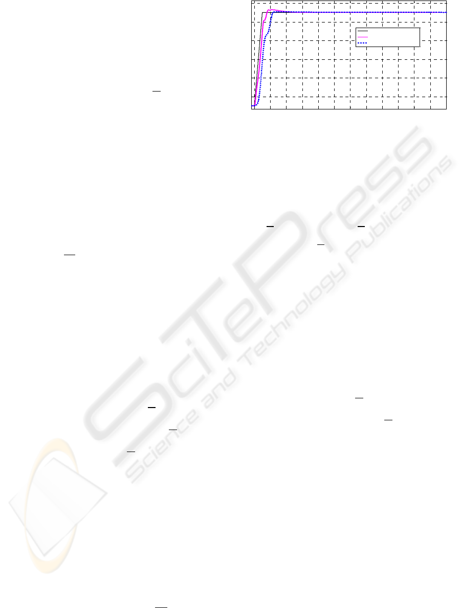
Figure 8: Experimental results in the intermediate
displacement zone.
The impedance control law (14) to be applied,
which is a simplified form of the general law (1), is
obtained by equalling the term of the angular
acceleration i (1n 3).
·
·
·
(14)
If the control law is analysed, apart from the
parameters to be tuned (K, B and M), it can be
observed that there is a term,
, which is the
torque measured when the arm interacts with the
environment. This torque can be the estimated
torque, as described for the hybrid control, but it is
not essential in the control law. This term was not
used in the law implemented, as the results were
analogous.
represents the static part of the
idynam c equation (12).
···sin
·
·
·
·sin
(15)
As can be observed, it is dependent on the mass
at the tip, and it is therefore not robust to mass
change. However, this mass can be estimated during
the free movement phase. The design parameters K,
B and M were experimentally adjusted and the
following values were obtained: K=3.1, B=0 and
M=0.5.
To close the torque loop, the most common
procedure is to use the direct reading by means of a
torque sensor placed on the actual rotation axis, as
done by Tsasarakis (2007) and Jia-Fan (2008).
However, as described in section 4 of this paper, an
estimator was used to calculate the torque exerted by
the antagonistic pair of muscles from the reading of
their position and their internal pressures.
0 1 2 3 4 5 6 7 8 9 10 11 12
36
38
40
42
44
46
Time[s]
Angl e[º]
Set-point
Hybrid Control
Impedance Control
POSITION/FORCE CONTROL OF A 1-DOF SET-UP POWERED BY PNEUMATIC MUSCLES
235
1 2 3 4 5 6 7 8 9 10
55
56
57
58
59
60
61
62
Time[s]
Angle[º]
Position set-point
Hybrid Control
Impedance Control
1 2 3 4 5 6 7 8 9 10
0
10
20
30
40
50
Time[s]
F[N]
Force set-point
Hybrid Control
Impedance Control
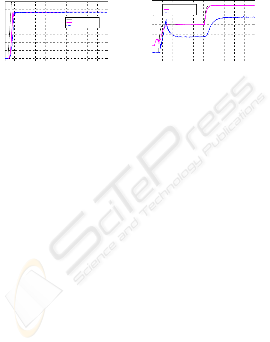
Figure 9: Position responses during a collision. Figure 10: Estimated force responses during a collision.
force executed by the pneumatic muscles against the
lower limit stop when the collision happens. In fact,
during the collision, controllers are not comparable
to each other. Hybrid control carries out the tracking
of a force set-point whereas the reaction force of the
impedance control is proportional to the error
between the position set-point and the collision
point. Force set-point for the hybrid control is 30 N
for the first 5 s and then increases up to 50 N. After
some initial disturbances due to the impact and the
commutation between the controllers, the estimated
force increases smoothly until it reaches the set-
point. This response could be faster, but the
parameters were tuned to achieve an acceptable
force control with a weight placed in the tip within
the range of 0 to 6 Kg. In the impedance control the
influence of the collision is lower, and after an initial
peak the estimated forced is limited. After the first 5
s position set-point increases, and the control reacts
to this rise increasing the torque as it is shown in the
graph of the force.
7 EXPERIMENTAL RESULTS
Initially, controllers were tuned by simulation, using
the non-linear model previously developed (Arrese-
Pujana, 2007). Continuous-time controllers were
discretized with sample time of 2 ms and then
embedded into the control hardware.
With the objective of comparing the behaviour of
both control techniques, Figure 8 shows the
experimental response to a position step of 10º with
a slope of 20º/s. This input signal has been applied
to the intermediate zone within the motion range.
Moreover, the arm has been loaded by attaching in
its tip a weight of 3 Kg. This trial has been carried
out in free movement without any collision with the
environment.
The decoupling between the position and the
force permits to adjust the hybrid control, thus it is
possible to obtain a very fast position response
which is almost identical in all the zones with a very
little overshoot. Impedance control is not used to
control explicitly the position, so, its response is
more conservative because the same control law and
the same tuning are used to control both the free
movements and the collisions with the environment.
Regarding the steady state error, both algorithms are
able to eliminate it.
The robustness of the controllers can be tested by
changes in the weight placed at the extreme of the
arm. In Figure 11 it can be observed that the tuning
performed for the hybrid controller is suitable to
manage collisions with different loads within the
range 0 to 6 Kg, although in the upper limit of the
range (with 6 Kg) a minor overshoot happens.
Hybrid control offers a robust behaviour in free
movements as well.
The trial showed in Figures 9 and 10 was
performed in order to study the behaviour of both
controllers with collisions. In this case, the arm is
initially 55º away from the vertical plane and it is
generated an ascendant position set-point with a
slope of 20º/s. The lower limit stop was located at
61.5º, so when the arm tries to track the set-point
and reaches this position a collision happens.
Analyzing the dynamic of the position response
(showed in Figure 9) it can be observed that the
rebound happened after the collision has bigger
amplitude with the hybrid control, due to the
commutation between the position control and the
force control. Figur 10 shows the estimate of the
Impedance control does not offer a robust
behaviour with changes in the load. In fact, the
algorithm (14) needs to specify the weight of the
mass placed at the extreme of the arm. To solve this
problem, it was developed an initialization function
which it is used to carry out a set of free movements
are useful to estimate the extra weight. Thus, the
control systems can work autonomously. Once the
extra weight is estimated the results showed in
Figure 12 are obtained for different tip masses
during a collision and maintaining the same control
parameters.
ICINCO 2009 - 6th International Conference on Informatics in Control, Automation and Robotics
236
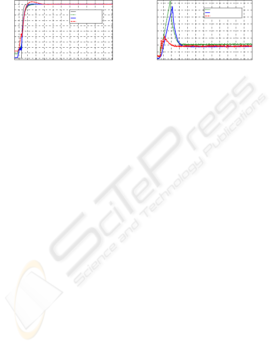
Figure 11: Estimated force response with different tip
masses for hybrid control.
Figure 12: Estimated force response with different tip
masses for impedance control.
8 CONCLUSIONS
This article is a study about the control issue of the
interaction with the environment of a 1-DOF
experimental set-up powered by pneumatic muscles.
Due to the non linear behaviour of this kind of
actuators the control of the mechatronic device is
very complex both in free movements and when it
comes into contact with an obstacle, having a
different response depends on the movement zone or
the position where the impact occurs. Moreover, the
possibility of loading the extreme of the arm with
extra weight requires using robust algorithms. The
main contribution of this paper is the design and
implementation of a torque/force estimator which is
used to close the control loops. In spite of having a
structural error derived from the equation used to
model the force of the muscles, this inaccuracy only
appears when the arm impacts with an obstacle and
this is not critical because the dynamic is not
affected.
ACKNOWLEDGEMENTS
The material used in this paper was partly supported
by the Spanish Ministry of Education and Science
and European FEDER Fund (research project
DPI2006-14928-C02-01).
REFERENCES
Thanh, T-D.C., Ahn, K.K.,2006. Nonlinear PID control to
improve the control performance of 2 axes pneumatic
artificial muscle manipulator using neural network. In
Mechatronics, no. 16, pp. 577-587.
Balasubramanian, K., Rattan, K.S., 2005. Trajectory
tracking control of a pneumatic muscle system using
fuzzy logic. In NAFIP’2005, Annual Meeting of the
North American Fuzzy Information Precessing Society.
Pujana-Arrese, A., Riaño, S., Arenas, J., Martinez-
Esnaola, A., Landaluze, J., 2008. H
∞
position Control of
a 1-DoF Arm Powered by Pneumatic Muscles. In the 8
th
Portuguese Conference on Automatic Control
CONTROLO’2008, 21-23 July 2008, Vila Real, Portugal.
Arenas, J., Pujana-Arrese, A., Riaño, S., Martinez-
Esnaola, A., Landaluze, J., 2008. Sliding-mode
Position Control of a 1-DoF Set-up based on
Pneumatic Muscles. In UKACC Control Conference
CONTROL2008, 2-4 Setember 2008, Manchester.
Tsagarakis, N.G., Caldwell, D.G., 2007. A compliant
exoskeleton for multi-planar upper limb physiotherapy
and trining. In ICAR'07, The International
Conference on Advanced Robotics, 21-24 August
2007, Jeju Island, Korea.
Martinez, F., Retolaza, I., Lecue, E., Basurko, J.,
Landaluze, J., 2007. Preliminary design of an upper
limb IAD (Intelligent Assist Device). In the 9th
European Conference for the Advancement of Assistive
Technology, AAATE 2007, October 3rd-5
th
, Donostia.
Martinez, F., Retolaza, I., Pujana-Arrese, A., Cenitagoya,
A., Basurko, J., Landaluze, J., 2008. Design of a Five
Actuated DoF Upper Limb Exoskeleton Oriented to
Workplace Help. 2008. In IEEE International
Conference on Biomedical Robotics and
Biomechatronics, IEEE BioRob 2008, 19-22 October
2008, Scottsdale, Arizona, U.S.A..
Pujana-Arrese, A., Arenas, J., Retolaza, I., Martinez-
Esnaola, A., Landaluze, J., 2007. Modelling in
Modelica of a pneumatic muscle: Application to
model an experimental set-up. In the 21st European
Conference on Modelling and Simulation ECMS2007,
4-6 June 2007, Prague.
Raibert, M.H., Craig J.J., 1981. Hybrid Position/Force
Control of Manipulators. In Trans. of the ASME, vol. 102.
Hogan, N., 1985. Impedance Control: An Approach to
Manipulation : Part I - Theory. Part II - Implementation.
Part III – Applications. In Journal of Dynamic Systems,
Measurement, and Control, 107, 1-24.
1 2 3 4 5 6 7 8 9 10 11 12
0
5
10
15
20
25
30
35
40
45
50
Time[s]
F[N]
Set-point
Hybrid Control 0Kg
Hybrid Control 3Kg
Hybrid Control 6Kg
1 2 3 4 5 6 7 8 9 10 11 12
0
5
10
15
20
25
30
35
40
Time [s]
F [N]
Impedance Control 0 Kg
Impedance Control 3 Kg
Impedance Control 6 Kg
Jia-Fan, Z., Can-Jun, Y., Ying, C., Yu, Z., Yi-Ming, D.,
2008. Modeling and control of a curved pneumatic
muscle actuatorfor wearable elbow exoskeleton. In
Mechatronics, no. 18, pp. 448-457, 2008.
POSITION/FORCE CONTROL OF A 1-DOF SET-UP POWERED BY PNEUMATIC MUSCLES
237
