
A MONOCULAR OCCUPANCY GRID FOR LOCAL
WMR NAVIGATION
Lluís Pacheco, Xavier Cufí
Technical School, Girona University, Av. Luís Santaló s/n, Girona, Spain
Ningsu Luo, Javier Cobos
Institut de Informàtica i Aplicacions, Girona University, Av. Lluís Santaló s/n, Girona, Spain
Keywords: Autonomous mobile robots, Computer vision, Path planning, Obstacle avoidance, Reactive navigation.
Abstract: This work introduces a new methodology to infer environment structure by using monocular techniques.
The monocular field of view is constrained to the vicinity of the mobile robot. The cooperative strategy
proposed combines DFF and qualitative structure techniques to obtain environment information. The
remarkable features of the strategy presented are its simplicity and the low computational cost. In this way,
a simplified DFF method, which uses only one frame, has been implemented; hence, scenario information
can be achieved when homogeneous radiance background constraint is accomplished. Further structure
analysis is developed by computing qualitative structure through time integration series of acquired frames;
within a tessellated probabilistic representation consisting in a local occupancy grid framework.
Furthermore, the camera pose knowledge is used to correlate the different overlapping image zones.
Moreover, time integration of the monocular frames allows a larger environment description suitable for
WMR local path planning. Hence, the reported work can be used in obstacle avoidance strategies or reactive
behaviours for navigation towards the desired objective.
1 INTRODUCTION
Perception of the environment is based on the sensor
system measurements that provide distances and
structure knowledge. This essential task could be
accomplished by different range systems like
ultrasonic sensors, laser rangefinders, or vision
based systems. All these sensors have their
advantages and disadvantages. However, computer
vision based methods, are one of the most attractive.
Therefore, they have many interesting advantages
that can be summarized as follows: the falling prices
of devices and richer information compared with the
other traditional ranging devices. In this way the
increasing capabilities of the personal computers,
offer an interesting range of real time applications.
Perception systems based on camera devices have
attracted robotic research due these interesting
features. Thus, machine vision systems have used
some features of eyes, such as stereopsis, optical
flow or accommodation, as meaningful clues. SVS
(stereo vision systems), OFM (optical flow methods)
and DFF (depth from focus) are all methods that
permit 3D scene recovery. Studies comparing SVS
and DFF are reported in (Schechner and Kiryati,
1998). The results show that while SVS has greater
resolution and sensitivity, DFF has greater
robustness, requires less computational effort and
can deal properly with correspondence and
occlusion problems. The need for several images of
the same scene, acquired with different optical
setups, may be considered as a significant drawback
in using DFF methods in major robotic applications.
The scientific community has proposed the use of
special cameras, such as a multi-focus camera that
acquires three images with three different focus
positions (Hiura and Matsuyama, 1998). However,
other proposals were developed due to a lack of
multi-focus commercial cameras. The use of DFF in
WMR (wheeled mobile robots) has been reported in
(Nourbakhsh, 1997); in which Noubakhsh used three
cameras with almost the same scene to achieve
robust and efficient obstacle detection.
This work presents a new cooperative monocular
strategy; where DFF and QSM (Qualitative
425
Pacheco L., Cufí X., Luo N. and Cobos J. (2009).
A MONOCULAR OCCUPANCY GRID FOR LOCAL WMR NAVIGATION.
In Proceedings of the 6th International Conference on Informatics in Control, Automation and Robotics - Robotics and Automation, pages 425-432
DOI: 10.5220/0002206704250432
Copyright
c
SciTePress

Structure Methods) are combined. Thus, one bit
depth can be obtained using the DFF methodology
as well as a set of multi-resolution focus thresholds,
when homogeneous radiance background constraint
is accomplished. However, when homogeneous
radiance constraint fails, we propose to use QSM
over discrepancy areas in order to infer environment
structure by using an occupancy grid framework.
Therefore, the main contributions of this research
are to propose the occupancy grid as a suitable
structure in order to infer qualitative obstacle
structure and obtaining larger scenario descriptions.
The results depicted are directed towards real
applications by using the WMR PRIM, which
consists of a differential driven one with a free
rotating wheel (Pacheco et al., 2008). The
experiments are orientated so as to obtain a local
map in the robot’s neighborhood that can be used to
plan navigation strategies.
This paper is organized as follows. In Section 1,
the main ideas and research objectives are presented.
Section 2 introduces the DFF methodology as well
as the algorithms and results implemented. Section 3
depicts the QSM concept and the related algorithms
used. In this way, the local occupancy grid
framework is also formulated as a way for time
integrating the acquired frames. In Section 4, the
experimental preliminary results are drawn by using
the mobile platform PRIM. In Section 5 the
conclusions and future research are presented.
2 THE CONSTRAINED DFF
SYSTEM DESCRIPTION
This section briefly introduces the DFF
methodology. The algorithms implemented as well
as their results are also depicted by using the
available WMR platform. Its significant contribution
is the use of a single image to obtain environment
information.
The DFF techniques use an image collection of the
same scene acquired at different focus positions.
Thus, the camera system PSF (point spread function)
for unfocused object points produces blurred image
points. The PSF frequency domain space transform
representations arise in a first order Bessel OTF
(optical transfer function), where its main lobe
volume can determine the FM (focus measure)
expressed as:
(
)
∫∫
= . ,
0
νωνω
ddIM
i
(1)
where I
i
denotes the image considered, ω and ν
represent the frequency components. Efficient
energy image measures have been proposed as FM
(Subbarao et al, 1992). Nayar has proposed a
modified Laplacian that improves the results in some
textures (Nayar and Nakagawa, 1994). The 3D scene
map and passive auto-focus consumer camera
systems are interesting applications solved by the
DFF. Recovering the 3D information from DFF
methods is known as SFF (shape from focus) (Nayar
and Nakagawa, 1994).
2.1 The DFF Monocular Algorithms
The algorithms of the machine vision system
implemented are based on important assumptions
that are generally obtained in normal indoor
scenarios, but also in many outdoor scenarios. These
constraints are flat and homogenous energy radiance
from the floor surface and experimental knowledge
of the focus measurement threshold values. Two
important aspects, image window size and camera
pose, should be considered. The size of windows
should be big enough to receive energy information.
For example, in the work of Surya, images of
150x150 pixels were used, and the focus measures
were computed in 15x15 pixel regions (Surya,
1994). The camera pose will set the scenario
perspective and consequently the floor position
coordinates that should be used in the WMR
navigation strategy. Figure 1 shows the robot and
camera configuration considered in this work,
where
α
,
β
and
ϕ
are angles of the vertical and
horizontal field of view and the tilt camera pose
respectively. The vertical coordinate of the camera is
represented by H. The robot coordinates
corresponding to each pixel can be computed using
trigonometric relationships and the corresponding
knowledge of the camera configuration (Horn,
1998). Using trigonometric relationships, the flat
floor scene coordinates can be computed as follows:
()
()
()
()
()
RK
C
C
K
HY
H
X
j
i
j
ji
≤≤=Δ
≤≤=Δ
Δ+−=
Δ
Δ+−
±=
j
i
,
K0
R
2K0
2tan
tan
2cos
α
α
β
β
ααϕ
β
ααϕ
(2)
K
i
and K
j
are parameters used for covering the
discrete space of the image pixels. Thus, R and C
represent the image resolution through the total
number of rows and columns. It should be noted that
for each row position corresponding to scene
ICINCO 2009 - 6th International Conference on Informatics in Control, Automation and Robotics
426
coordinates Y
j
, there are C column coordinates X
i,j
.
The above equations provide the available local map
coordinates when no obstacle is detected. The
algorithms used are explained in the remainder of
this subsection. The multigrid representation using
low-pass filtering processes can improve the surface
radiance homogeneity. Scale space representations
can reduce the search space, increasing the
computation performance (Gonzalez and Woods,
2002). Therefore, a Gaussian filter is applied to the
frames acquired in PAL format, at 768x576 pixels.
Three decreasing resolution levels have been used
with picture sizes of 384x288, 192x144 and 96x72.
The average image brightness is also computed. In
order to achieve greater robustness against changes
in lightness, brightness normalization is performed
(Surya, 1994). The image energy is computed, over
3x3 windows at the top level of the scale-space,
using the modified Laplacian method:
() ()
(
)( )
()( )( )
1,1,,2
1,1,2,
+−−−
++−−−=
yxiyxiyxi
xiyxiyxiyxML
(3)
where i(x,y) represents the corresponding pixel value
at spatial coordinates (x,y). The 96x72 scale-space is
decreased using a 9x7x2 array, where each cell
represents the Laplacian mean value and the
corresponding standard deviation mean computed
over 10x10 pixel patches. Another interesting
statistical parameter that has been used is the
standard deviation, which relates to the homogeneity
of the floor energy values. The 9x7x2 array is
explored, from top to bottom; floor segmentation is
carried out, using both energy and standard
deviation thresholds.
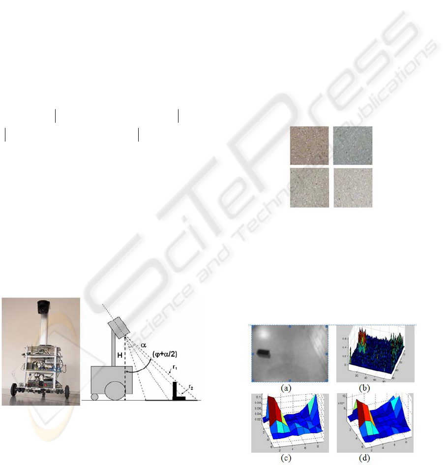
Figure 1: The robot PRIM and the monocular camera
configuration. Where α is set to 37º, β (horizontal angle)
of 48º, H set to 109cm, and a tilt angle of 32º.
2.2 One Bit DFF Experimental Results
The floor threshold has been experimentally
computed by averaging several floor images
acquired in our lab environment with different kinds
of illumination (from 200-2000 lx). Light
illumination can change from 2000 lx when light
from the sun is clearly present where there is
sunlight through the windows, to less than 200 lx in
the darker corridor zones. Figure 2 depicts high
resolution (130x130 pixel windows) corresponding
to different floor images used to compute focus
measurement thresholds where the floor texture is
clearly visible. It is in the locality of those points
where the information about radiance is obtained.
Hence, the results obtained with the available
experimental set up show the decreasing values
when the distance between the camera and the floor
is increased. A more complete description of the
energy floor radiance measures obtained for each
9x7 visual perception row is shown in (Pacheco et
al., 2007); in which the image perspective emerges
from a set of multi-resolution thresholds as a
function of the camera distances.
Figure 2: Fragments of high resolution floor images
(768x576 pixels under different light conditions
corresponding to 300, 800, 1400 and 2000 lx, respectively.
Figure 3 shows the modified Laplacian energy
and standard deviation values using 9x7 and 96x72
space-resolutions, when typical indoor obstacles are
presented. It is shown that 9x7 space resolutions can
detect radiance discontinuities but because there was
Figure 3: (a) Image with obstacles, 96x72; (b) Modified
Laplacian measures; (c) 9x7 Modified Laplacian mean
values; (d) ) 9x7 standard deviation mean.
A MONOCULAR OCCUPANCY GRID FOR LOCAL WMR NAVIGATION
427
a great lack of resolution manifested through soft
slopes. Thus, it is necessary to use a fine space-
resolution to attain the sharper edges. In this work,
9x7 resolutions are used to detect the local patches
where obstacle segmentation is computed within
96x72 space resolution.
Despite the good results achieved, some further
improvements should be considered. Hence, when
radiance floor discontinuites occur they can be
considered obstacles (false positives in some cases).
Therefore in next section OFM is introduced, within
the occupancy grid framework, to improve the one
bit DFF methodology.
3 QUALITATIVE STRUCTURE
METODS AND OCCUPACY
GRID
The camera pose and local field of view will set the
QSM algorithms reported in this section. The
different optical flow quantitative approaches are
generally based on two classical feasible
assumptions, which are BCM (brightness constancy
model), and optical flow smoothness. Thus, image
motion discontinuities are due to the depth and
motion discontinuity boundaries. Hence, there are
places where image flow changes are suddenly
useful as image segmentation clues, but can cause
problems such as optical flow estimation clusters.
Therefore, suggestions made to compute the
algorithms over small neighborhoods, or region-
based matched methods have turn on. Combining
local and global optic flow differential methods have
been proposed as a way to share benefits from the
complementary advantages and short-comings
(Bruhn, 2002).
The occupancy field can be depicted by a
probability density function that relates sensor
measures to the real cell state. The tessellated
probabilistic representation has been widely adopted
by the scientific community in navigation or
mapping issues. Indoor applications research has
been mainly concentrated on SLAM (simultaneous
localization and mapping) issues (Thrun, 2002).
Their use allows sensor fusion or multiple layer
representations to segment dynamic objects (Coue,
2006). The perception system used, in this work,
consists in monocular and odometer system data.
The use of these systems in SLAM is reported in
(Cumani et al., 2004).
The main difference of the research depicted in
this paper, as compared with Cumani research, is the
occupancy grid use that allows integration of
multiples frames without constraining their number.
Furthermore, it is obtained a local map description
suitable for navigation. Thus, the occupancy grid
developed research increase the camera narrow field
of view, which provides just the vicinity of the robot
where floor only is expected to be found. Moreover,
the floor model is also proposed as a contribution in
order to build the 2D occupancy grid; hence obstacle
binary results are time integrated within the local
occupancy grid framework by considering such
model. The obstacle structure could be inferred by
considering optical flow magnification change
discrepancies from the floor model.
3.1 The Local QSM Approach
In the present research the camera field of view
depicts only the vicinity of the WMR. Perspective
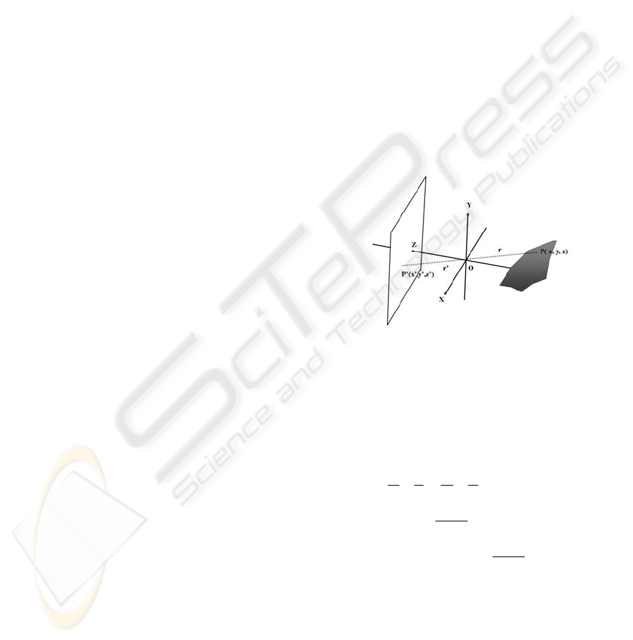
projection, as shown in Figure 4, should be assumed.
Figure 4: Camera system producing an image that is a
perspective projection of the world.
Introducing the coordinate system, where z
coordinates are aligned to the optical camera, and
the xy-plane is parallel to the image plane, the image
P’ corresponding to the point P of a scene object is
given by the following expressions:
α
α
α
α
α
α
sec'
cos
'
'cos''
sec
cos
cos
'
'
'
'
z
z
rrz
z
z
r
rz
z
y
z
y
z
x
z
x
==⇒=
−=−=⇒
=−==
(4)
Where z’ in the distance between image plane
and the camera lenses, and x’ and y’ are the image
coordinates. The object point coordinates, referred to
the optic center O, are given by P= (X, Y, Z), being r
de distance between P and O and
α
the angle. The
ratio of the distance between two points measured in
the image plane and the corresponding points
measured in the scene is called magnification m.
ICINCO 2009 - 6th International Conference on Informatics in Control, Automation and Robotics
428
()()
() ()
22
22
z
z
yx
yx
m
′
=
Δ+Δ
Δ
′
+Δ
′
=
(5)
For reduced field of views when the optical rays
are parallel to the optical axis the magnification m is
constant for all the image points. However, due to
the field of view and camera pose assumed in this
research, magnification changes are expected even
when just considering a flat floor scenario. Hence,
the perspective image formation model arises in
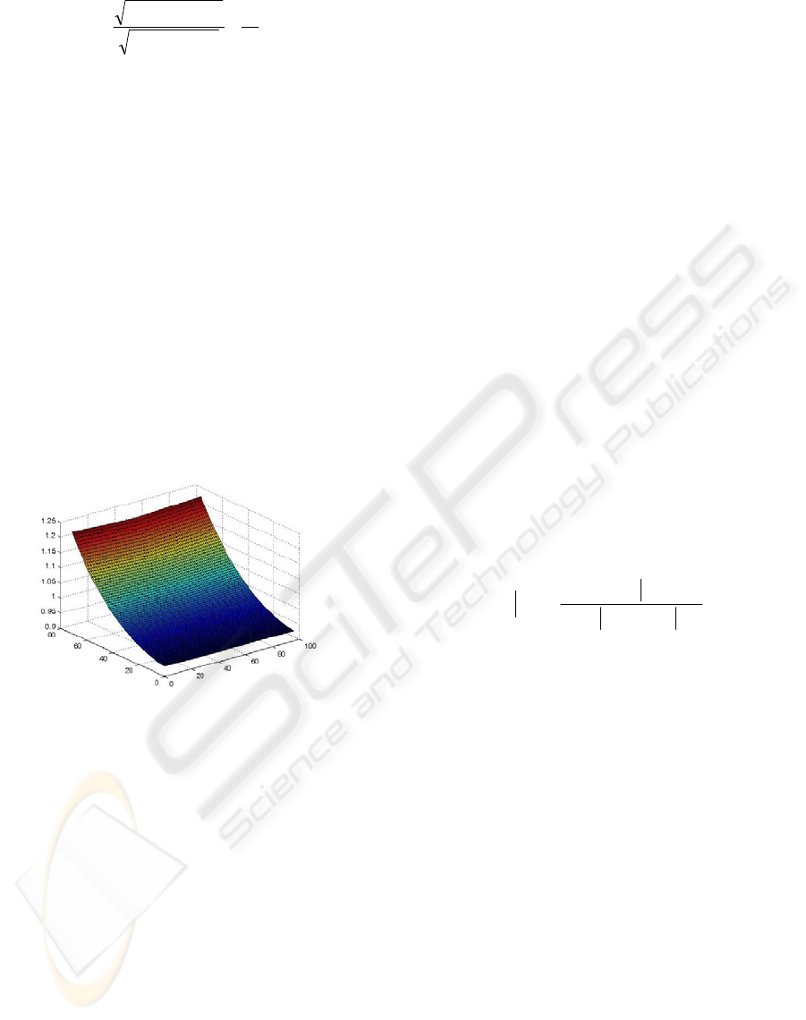
magnification changes. Figure 5 shows the
magnification changes of the floor model by
considering the optical axis ray as the unit of
magnification. Therefore, these changes in
magnification are made it more complicated to look
for image patches with similar motion in order to
detect obstacle depth boundaries. However, by using
the floor model and the odometer system data,
binary floor results can be predicted from frame to
frame; then predicted discontinuities arise due to the
3D non floor obstacle shapes that produce
unexpected image boundaries.
Figure 5: Magnification changes of the floor model by
considering the optical axis ray as the unit of
magnification. The bigger magnification is attained at
closer robot positions.
The machine vision system algorithms
implemented are based on binary results obtained by
the one bit DFF algorithms explained in subsection
2.2. Binary images are obtained in the 96x72 space
resolution level, and blob analysis is developed. The
blob areas and the extremes of their coordinates are
computed and small blobs are removed. Then, the
image is analyzed from top to bottom, searching for
possible non floor regions. Hence, the QSM can be
used to detect the possible obstacles, when important
floor energy radiance discrepancies are met.
Therefore, using relative robot coordinate
increments provided by the odometer system,
qualitative structure estimation could be done by
comparing predicted positions with the binary
results obtained. The time integration of the different
frames acquired is introduced in the next section.
Thus, the robot coherent interaction with the world
can be addressed by using the occupancy grid
framework that provides a robust and unified
approach to a variety of problems in spatial robot
perception and navigation (Elfes, 1989).
3.2 The Local Occupancy Grid
Framework
The occupancy grid is considered to be a discrete
stochastic process defined over a set of continuous
spatial coordinates (x, y). Hence, the space is divided
into a finite number of cells representing a 2D
position, 1
≤
j
≤
R 1
≤
i
≤
C. The R and C parameters
are the number of rows and columns of the grid
respectively. The cell column coordinates are
designated by X
i
and the rows by Y
j
. It is assumed
that local occupancy grid data is provided by the on-
robot perception system. The occupancy probability
is divided into two ranges only: free and occupied.
The grid can be updated by using the sensor models
and the current information. Hence, given a sensor
measurement m, the occupancy probability P(O
,
) for
the different cells, P(C
ij
), can be computed by
applying Bayes rule:
()
(
)
()()
/O
ijij
ij
ij
CPOCP
OCP
COP
+
=
(6)
Hence, the probability that a cell is occupied
P(O
⎜
C
ij
) is given by the cell occupancy sensor
measurement statistics P(C
ij
⎜
O) by also considering
the probability that the cell will be free P(C
ij
⎜
/O).
Thus, free cells have binary results equal to zero;
these non-occupied cells belong to coordinates for
image pixels within floor radiance thresholds. Other
available coordinates are provided through time
integration of the acquired frames when radiance
energy is bigger than threshold values, by using the
floor model, and looking for coincidences with the
acquired frames. The unknown probability value is
set to 0.5. Therefore, by using the expression (6)
with the predicted occupied cells and acquired
frames, the grid positions belonging to the floor will
provide larger occupancy values. Obstacle positions
give intermediate occupancy probabilities due to the
discrepancies between the predicted and the
acquired image values that arise due to the 3D
obstacle shape. Next section depicts some
preliminary results experimented with the available
WMR platform.
A MONOCULAR OCCUPANCY GRID FOR LOCAL WMR NAVIGATION
429
(a) (b) (c)
(d) (e)
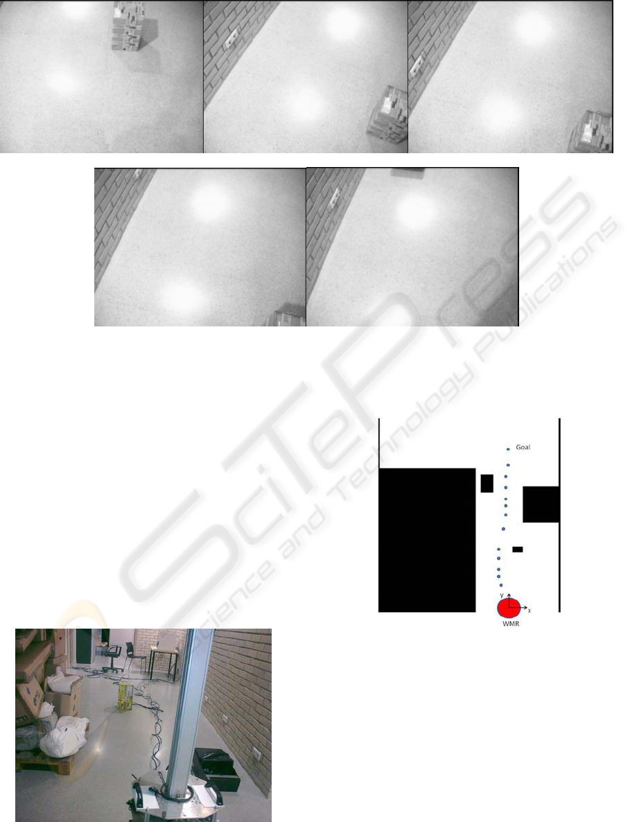
Figure 8.a, 8.b, 8.c, 8.d, and 8.e: It is depicted the monocular frames acquired while the WMR is avoiding the first obstacle
placed on the direction towards the objective.
4 ON-ROBOT EXPERIENCES
In this section are presented some experimental
results using the WMR PRIM. Thus, local
navigation with static obstacles is used as a
preliminary test of the research introduced in this
paper. The navigation and control strategy used,
under this reduced field of view, is introduced in
other author’s work (Pacheco and Luo, 2007).
Therefore, the maximum geometric size of the closer
obstacle is considered in order to plan safety
navigation towards the desired coordinates.
Figure 6: It is presented the real scenario that has been
drawn in Figure 7. It is shown the obstacles placed on the
floor that the WMR should avoid.
Figure 7: Simplified map scenario where the robot
trajectory toward the goal is depicted with blue dots. The
obstacles are drawn in black.
Figure 6 shows the scenario where the
experiment has been done, and Figure 7 depicts the
simplified map scenario with the WMR achieved
trajectory.
Thus, Figure 7 shows the lab environment map
and the path followed when the WMR starts at the
position (0, 0, 90º) towards the desired coordinates
(0, 460cm). The scenario contains some static
obstacles that the WMR should avoid.
Table 1 depicts the robot coordinates and acquired
frames during the WMR navigation.
ICINCO 2009 - 6th International Conference on Informatics in Control, Automation and Robotics
430
(a) (b) (c)
(d) (e)
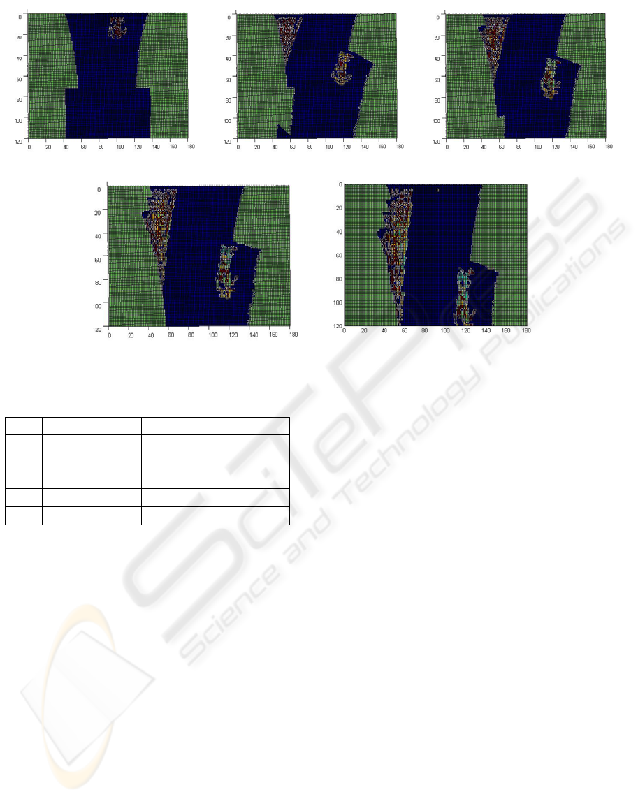
Figure 9: Sequence of occupancy grids obtained by integrating the first 5 acquired frames.
Table 1: Coordinates from where the frames are acquired.
F.1 (0, 0, 90º) F.7 (1, 293, 76º)
F.2 (-11, 66, 110º) F.8 (4, 315, 88º)
F.3 (-21, 108, 99º) F.9 (4, 339, 96º)
F.4 (-25, 141, 97º) F.10 (6, 375, 89º)
F.5 (-26, 176, 94º) F.11 (4, 415, 100º)
F. 6 (-8, 248, 83º) F.12 (12, 456, 74º)
The first 5 frames are acquired during the
obstacle avoidance strategy of the first obstacle
placed in the middle of the corridor. Figure 8.a, 8.b,
8.c, and 8.d. show these frames.
The first obstacle avoidance strategy consists
into turn to the left in order to avoid the collision
with the obstacle that appears at the first four
frames. It is noted that fifth frame, Figure 8.e,
depicts a part of the scenario where doesn’t appear
the first obstacleThe local occupancy grid built by
integrating the first 5 frames is shown in Figure 9.a,
9.b, 9.c, 9.d, and 9.e. It is depicted that in the first
frame only the front obstacle is perceived. However,
when the other frames are integrated the left wall is
integrated. It is observed how the WMR navigation
is constrained by the different obstacles obtained on
the acquired frames and integrated within the
occupancy grid. Therefore the navigation is
constrained by both obstacles. Moreover the fifth
frame is integrated in Figure 9.e where appear as
time integrated the front obstacle and the left wall.
Hence, the monocular occupancy grid methodology
presented increases the field of view perception, and
a better navigation strategy can be planned. The
integration of multiple monocular frames also can be
used as a framework in order to infer 3D obstacle
structure.
5 CONCLUSIONS
The methodology presented in this research has
provided a local map suitable for WMR navigation.
Therefore a short-term memory has been obtained.
Navigation advantages by using short-term memory
were reported in previous research (Schäfer et al.,
07). However, experimental results conducted to
obtain the obstacle structure have some aspects that
should focus the future work. The obstacle shape is
larger than the real shape due to the magnification
changes that arise of perspective. The lack of
accuracy increases the path-width, and consequently
this can result in larger trajectories or even infeasible
path perceptions where available paths are possible.
3D obstacle structure can solve the above problem.
But, the results obtained in order to obtain 3D
information have some mismatches when
overlapping areas between predicted and obtained
blobs are analysed. The errors can be produced by
the following sources:
• Odometry errors.
• Camera calibration errors.
A MONOCULAR OCCUPANCY GRID FOR LOCAL WMR NAVIGATION
431

• Flat floor model differences.
Future work will be addressed to solve the above
problems. We believe that the occupancy grid
framework can be used to obtain 3D obstacle
structure. Therefore, there is not limitation
concerning to the number of frames that can be time-
integrated. The future goal will consist in to find a
set of parameters in order to infer 3D obstacle
structure. These set of parameters should be
independent of the source of errors pointed in this
section. The knowledge of 3D structure can afford
several benefits that can be summarised as follows:
• To reduce the trajectories.
• Visual Odometry.
• Landmark detection.
Despite the work that remains undone the
methodology presented can be used to direct the
future research. Moreover, some good features and
results are presented in this work.
ACKNOWLEDGEMENTS
This work has been partially funded by the
Commission of Science and Technology of Spain
(CICYT) through the coordinated project DPI-2007-
66796-C03-02, and by the Government of Catalonia
through the Network Xartap and the consolidated
research group’s grant SGR2005-01008.
REFERENCES
Bruhn A., Weickert J., Schnörr C., 2002. Combining the
advantages of local and global optimal flow methods,
In Proc. Pattern Recognition, Lect. Notes in Comp.
Science, Springer-Verlag, 454-462.
Coue, C., Pradalier, C., Laugier, C., Fraichard, T.,
Bessiere, P., 2006. Bayesian Occupancy Filtering for
Multitarget Tracking: An Automotive Application.
The Inter. Journal of Robotics Research, 25(1) 19-30.
Cumani A., Denasi S., Guiducci A., Quaglia G., 2004.
Integrating Monocular Vision and Odometry for
SLAM. WSEAS Trans. on Computers, 3(3) 625-630.
Elfes, A., 1989. Using occupancy grids for mobile robot
perception and navigation. IEEE Computer, 22(6) 46-
57 .
Gonzalez, R. C., Woods, R. E., 2002. Digital Image
Processing, Prentice Hall Int. Ed., Second Edition.
Hiura, S., Matsuyama, T., 1998. Depth Measurement by
the Multi-Focus Camera, Proc. IEEE CVPR, 953-959.
Horn, B. K. P., 1998. Robot Vision, McGraw-Hill Book
Company, MIT Press Edition, 12
th
printing.
Nayar S.K., Nakagawa, Y., 1994. Shape from Focus, IEEE
Trans. PAMI, 16(8), 824-831.
Nourbakhsh, I., Andre, D., Tomasi, C., Genesereth, M.R.,
1997. Mobile Robot Obstacle Avoidance via Depth
from Focus, Robotics and Autom. Systems, Vol. 22,
151-158.
Pacheco, L., Luo, N., 2007. Trajectory Planning with
Control Horizon Based on Narrow Local Occupancy
Grid Perception. Lect. Notes in Control and Inform.
Sciences 360, Springer-Verlag, pp. 99-106.
Pacheco, L., Cufí, X., Cobos, J., 2007. Constrained
Monocular Obstacle Perception with Just One Frame,
Lect. Notes in Comp. Science, Springer-Verlag, Pattern
Recog. and Image Analysis, Vol. 1, 611-619.
Pacheco, L., Luo, N., Ferrer, I., Cufí,, X., 2008. Control
Education within a Multidisciplinary Summer Course
on Applied Mobile Robotics, Proc. 17th IFAC World
Congress, pp. 11660-11665.
Schäfer H., Proetzsch M., Berns K., 2007. Obstacle
Detection in Mobile Outdoor Robots, Proc. Inter.
Conf. on Informatics in Control, Autom. and Robotics,
pp. 141-148.
Schechner, Y., Kiryati, N., 1998. Depth from Defocus vs.
Stereo: How Different Really Are They?, Proc. IEEE
CVPR, Vol. 2, 256-261.
Subbarao, M., Choi, T., Nikzad, A., 1992. Focusing
Techniques, Tech. Report 92.09.04, Stony Brook,
NewYork.
Surya, G., 1994. Three Dimensional Scene Recovery from
Image Defocus. PHD thesis, Stony Brook, New York.
Thrun S., 2002. Robotic mapping: a survey. Exploring
Artificial Intelligence in the New Millennium, Morgan
Kaufmann, San Mateo.
ICINCO 2009 - 6th International Conference on Informatics in Control, Automation and Robotics
432
