
Keywords: 3-D Registration, Unmanned Ground Vehicle, DSM, Post Estimation.
Abstract: In this paper, we propose a new approach which registers a range image which is acquired from a 3-D range
sensor to a DSM to estimate the 3-D pose of an unmanned ground vehicle. Generally, 3-D registration is
divided into two parts that called as coarse and refinement steps. Above all, a proper feature matching
technique is demanded between the DSM and the range image for the coarse registration to register
precisely and speedy. We generated signatures using shape parameterization about the DSM and the range
images and got a 3-D rigid transformation by matching them to minimize registration error.
1 INTRODUCTION
To achieve duty of an UGV(unmanned ground
vehicle), a navigation system is essential to provide
information such as the position of the vehicle,
travelling speed, and etc. However, high accuracy
navigation systems are usually high price so that
additional costs are required for operating them.
Therefore, in order to account for productivity and
an effectiveness of the UGV, a low-priced
navigation system is needed. By the way, solutions
which revise the navigation error are demanded
simultaneously. To overcome this problem, it is
necessary to obtain range images using multiplex
sensors mounted on the UGV and develop a real-
time algorithm which revises the navigation error
using a 3-D registration technique with a pre-
produced DSM(digital surface model).
The 3-D registration technique is to find a rigid
transformation which best fits the data to its
corresponding model, i.e., it is a process which
transforms 3-D geometrical information such as
vertices and surfaces acquired from each private
coordinate system into a common coordinate system.
In general, the 3-D registration techniques are
divided into two parts that one of them is called as
coarse registration which computes an initial
estimation of the rigid motion between two clouds of
points and the other is called as refine registration
which minimizes registration error using the initial
estimation. Hence according to the accuracy of the
initial estimation, the performance of last
registration refinement becomes satisfactory or not.
The key point for the successful coarse
registration is to extract appropriate correspondences
which have reliability between two objects. There
exist a number of the feature extraction methods
which can be grouped in two fundamental
REGISTRATION OF DSM AND RANGE IMAGES FO
R
3-D POSE ESTIMATION OF AN UNMANNED GROUND
VEHICLE
Sung-In Choi, Soon-Yong Park
Department of Computer Engineering, Kyungpook National University
Daegu, 702-701, Republic of Korea
Jaekyoung Moon
School of Electrical Engineering and Computer Science, Kyungpook National University
Daegu, 702-701, Republic of Korea
Jun Kim, Yong-Woon Park
Agency for Defense Development
Yuseong PO Box 35-1, Daejeon 305-600, Republic of Korea
507
Choi S., Park S., Moon J., Kim J. and Park Y. (2009).
REGISTRATION OF DSM AND RANGE IMAGES FOR3-D POSE ESTIMATION OF AN UNMANNED GROUND VEHICLE .
In Proceedings of the Fourth International Conference on Computer Vision Theory and Applications, pages 507-511
DOI: 10.5220/0001798505070511
Copyright
c
SciTePress

approaches. One of them is 2-D image based
extraction that using corners, edges or chromatic
information and the other is using 3-D geometrical
information such as surface normal and Point
fingerprint (Sun, 2001).
To extract feature points, In (Vandapel, 2006),
Nicolas Vandapel et al. used spin-images for the
terrain model and Soon-Yong Park et al. proposed
SDEBM(sampled depth edge block matching) using
edge information of 3-D model (Park, 2007).
In this paper, we present a new registration
technique which can be applied for the 3-D pose
estimation of an UGV. For the registration, we
generated signatures using shape parameterization
about the DSM and the range images and got a 3-D
rigid transformation by matching them to minimize
registration error.
2 COARSE REGISTRATION BY
MATCHING LOCAL
SIGNATURE
Because our work is an extension of signature based
matching technique, in this section, we review how
signatures are generated and used in previous coarse
registration cases.
2.1 Signature Matching
Generally, the coarse registration between two 3-D
terrain models is accomplished by constructing and
matching signature at selected points on both
surfaces which are invariant by changes in pose.
Correspondences are pair-wised between points with
similar signature and after filtering of the
correspondences, the Euclidean transformation that
registers the two terrain models coarsely is
computed by the correspondences. Here is
noticeable point that to design appropriate signature
which represents invariant characteristic well affects
the matching accuracy.
2.2 Image-based Signature
There are many surface representation techniques
which used for object matching or recognition.
Especially, characterization into a 2-D image by
shape parameterization has been one of the most
popular methods for surface representation. The
spin-images algorithm which introduced by Johnson
and Hebert in (Johnson, 1999) is a typical
application that apply the imaging mechanism to
represent the surface shape. They used two factors
for generating the signature: radial coordinate is a
distance between the central point and a certain
point which is projected into the tangent plane from
a neighboring point x and the elevation coordinate
is the signed perpendicular distance to the tangent
plane. Using these distances, a signature is generated
representing on the x-axis and on the y-axis. As
another well-known image based signature, there is
a surface signature that proposed by Yamany and
Farag in (Yamany, 1999). The main idea of this
approach is to encode the distance and normal
variation between a central point and every other
feature points in the signature. In similar way to the
spin-images, a signature is also generated by
representing the distance and the normal variation on
the x-axis and the y-axis separately.
The main advantage of this image-based signature
matching technique comes from compactness and
stable. Hence it is possible to perform simple and
efficient computation of the similarity of two
surfaces patch by comparing the signatures.
Considering this advantage, in our research, we
aimed at designing a signature that is invariant and
can be computed efficiently in the same manner as
those registration cases.
3 A NEW APPROACH FOR
TERRAIN MAPPING
3.1 KNU Point Signature
Figure 1. shows the fundamental scheme of our
approach. The signature image is generated as
follows: for a central point which is defined by its
3-D coordinates and the normal
, each
neighboring point with its normal
in the
support region can be related by
x
,,
(1)
,
·
,
·
The and are respectively defined as a Euclidean
distance and an inner product of the normals
between central point and each other points and is
defined as a direction angle. Like the spin-image, we
also generated a signature representing on the x-
axis and on y-axis but the bins are filled up with
an accumulation of -value whereas the each bin of
the spin-image contains the number of points that
belong to the corresponding region.
VISAPP 2009 - International Conference on Computer Vision Theory and Applications
508
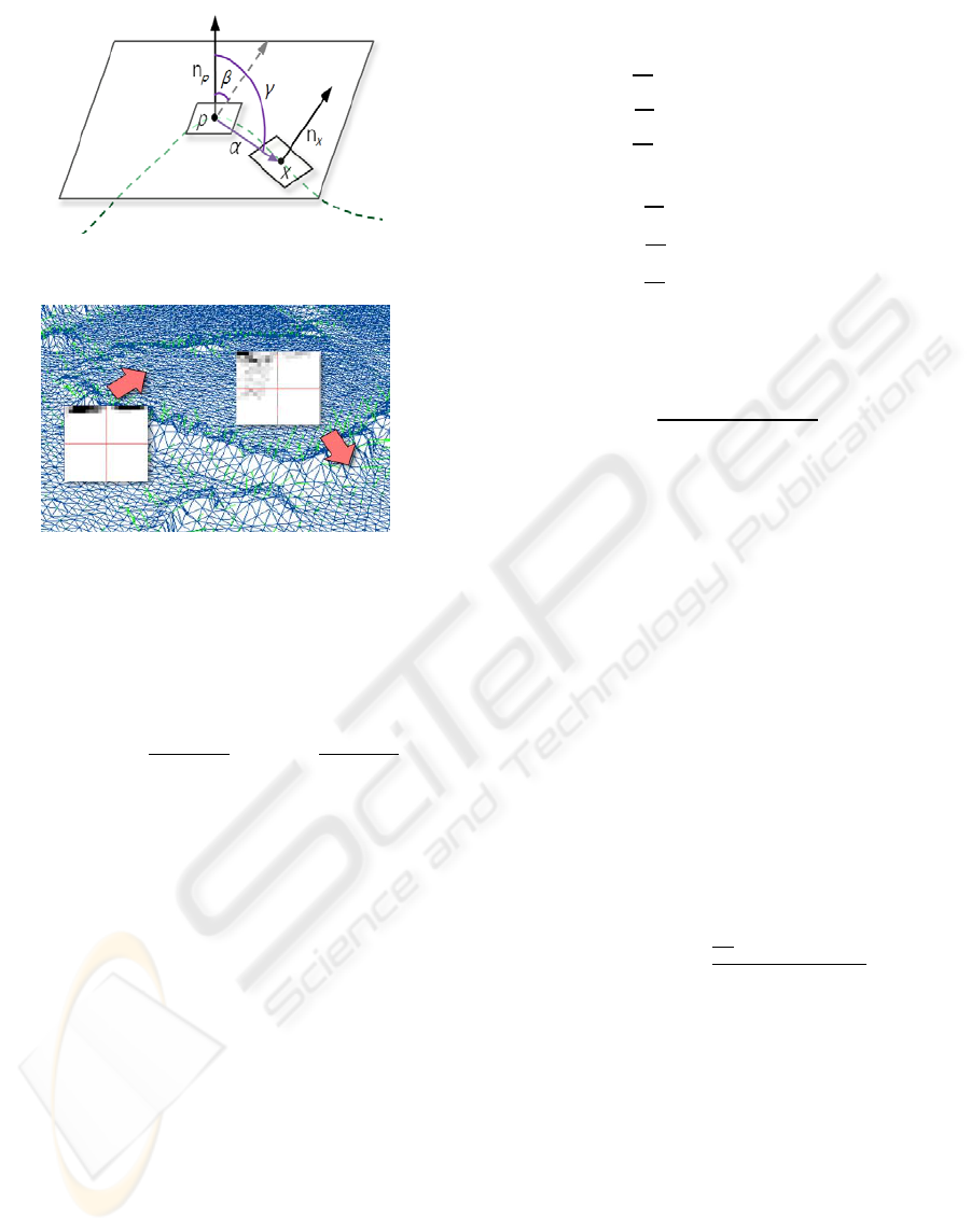
Figure 1: The fundamental scheme of KNU point signature.
Figure 2: Local terrain characterization.
Since and are in real number space, the
quantization procedure for generating the images is
needed. When the maximum and the minimum value
of and are given, using definition (2), an image
coordinate I can be determined.
,
,
j)(2)
3.2 Feature Selection Strategy
In general, a terrain data consists of millions of
vertices and thus it is not practical to use all of them
as candidate features for matching. Especially points
in flat area have less useful information for
registration. In such regions there is high mutual
similarity and finally, operating the UGV’s point of
view, the facts will affect real-time efficiency of
whole system and matching accuracy. Therefore, it
is necessary to define features take into account the
geometrical attribute of the 3-D shape and the
matching algorithm must be performed between the
features of the objects to efficiently correlate surface
points.
To extract available features, exploring with
respect to former territory of the 3-D model, we took
fractions of regular size and performed evaluation
about flatness, and then the results of the evaluation
were saved into an array which called as feature map.
As shown in the figure 3, there is a NxN patch on the
surface mesh and variance of normals of the vertices
at the patch is computed as follows:
∑
(3)
∑
∑
∑
∑
∑
V
X
,V
Y
,V
Z
) is central point’s 3-D coordinates of
the patch. After measuring the variance, using
definition (4), the patch can be classified as a good
or a bad feature.
(4)
> threshold
Once a classification had been achieved, the result
will be saved into a cell of the feature map. After
this, the feature map will be referenced at run-time
matching.
3.3 Signature Matching
The main purpose of this step is to establish a set of
correspondences between the DSM and the range
data. All signatures have same image size so that the
general template matching method such as SSD(sum
of squared differences), SAD(sum of absolute
distance) and NCC(normalized correlation
coefficient) can be used as a matching solution. For
the matching, we used the NCC. Let P be one of
range data’s signature and Q be one of the DSM’s
signature. Then the correlation coefficient R(P, Q) is
calculated by
,
∑
·
(5)
is the total number of pixels in the domain D
which is defines over the signature image size.
When R is high, the signature P and Q are similar
and when R is low, they are not similar.
In terrain matching scenario, comparing signature
directly without any restriction often drops the real-
time efficiency. Hence, we applied search range as a
constraint to perform the matching algorithm. In this
paper, the search range is specified by 25m in
position of the UGV.
REGISTRATION OF DSM AND RANGE IMAGES FOR3-D POSE ESTIMATION OF AN UNMANNED GROUND
VEHICLE
509
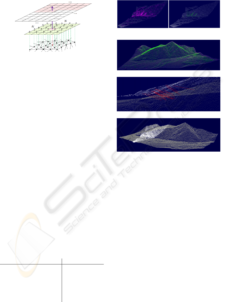
Figure 3: Feature map construction.
4 EXPERIMENTAL RESULT
The experiment was performed with the assumption
that an UGV is moving on the field and a sequence
of range images are obtained continuously from a
range sensor. The range sensor has 45 degree of
field of view and the sensing distance is from 50m to
1km and the range image’s resolution is 128x128. At
this point in time, because of absence of real range
data, we have simulated the scenario using OpenGL.
After estimating initial transformation, for
refinement, we used ICP algorithm (Besl, 1992)
which is widely used for minimizing registration
error. Since original ICP algorithm has time
consuming problem, we applied kd-tree algorithm to
speed-up the ICP and the iteration count for ICP was
selected by 50.
Figure 4 shows the results of the registration
process in order of precedence. Many features are
found at the bush of the ridge and the boundary
between the mountain and the field (fig. 4-a) and
through uniform sampling, the best candidates for
matching were selected (fig. 4-b, 4-c). After
matching process, the correspondences also
established appropriately (fig. 4-d). Finally, we
could notice that the range image was fitted into the
DSM(fig. 4-e).
Table 1. provides timing information and details
on the registration process. As expected, the
matching step keeps the most of registration time.
Table 1: Registration Statistics.
(a) Feature extraction (b) Sampled features of
a range image
(c) Sampled feature of the DSM
(d) A set of correspondences
(e) The result of registration
Figure 4: The total procedure of our approach.
5 CONCLUSIONS
In this paper, we have described registration
technique for 3-D pose estimation of an unmanned
ground vehicle. Using a signature which includes 3-
D geometrical characteristic by shape parameter-
zation, a set of correspondences can be established
and used for the coarse registration.
In future work, we intend to conduct a more
thorough analysis on the registration performance
and through coupling with the 2-D based feature
extraction method, we would like to improve the
registration performance.
ACKNOWLEDGEMENTS
This research has been supported by funding from
the Agency for Defense Development in Korea.
Step Average time (sec)
Feature selection 0.033
Signature generation 0.001
Matching the correspondences 3.157
Initial transformation
estimation
0.489
ICP using kd-tree (50 times
iter.)
0.193
VISAPP 2009 - International Conference on Computer Vision Theory and Applications
510

REFERENCES
Sun, Y., Abidi, M., 2001, Surface matching by 3d point’s
fingerprint, Proc. Of 8
th
Int. Conf. Computer Vision
(ICCV), pages 263-269
Vandapel N., Donamukkala, R., R., Hebert, M., 2006, The
International Journal of Robotics Research, Vol. 25,
No. 1, pp. 31-51.
Park, S., Baek, J., 2007. Online Multi-view Image
Registration using Geometric and Photometric Feature
Tracking, The 6
th
international Conference on 3-D
Digital Imaging and Modeling.
Johnson. A., Hebert, M., 1999. Using spin images for
efficient object recognition in cluttered 3d scenes,
IEEE TPAMI, 21(5): 433-449
Yamany, S., Farag, A., 1999. Free-form surface
registration using surface signatures. Proc. of 7th Int.
Conf. Computer Vision (ICCV), pages 1098–1104.
Besl, P., McKay, N. 1992. A method for registration of 3-
D shapes, IEEE Trans. Pattern Anal. Mach. Intell. 14
(2): 239-256
REGISTRATION OF DSM AND RANGE IMAGES FOR3-D POSE ESTIMATION OF AN UNMANNED GROUND
VEHICLE
511
