
ATTENTION MODELS FOR VERGENCE MOVEMENTS BASED ON
THE JAMF FRAMEWORK AND THE POPEYE ROBOT
Niklas Wilming, Felix Wolfsteller, Peter König
Institute of Cognitive Science, University of Osnabrück, Albrechtstr. 28, Osnabrück, Germany
Rui Caseiro, João Xavier, Helder Araújo
Institute of Systems and Robotics - ISR, University of Coimbra, Portugal
Keywords:
Stereo vision, Visual attention, Active vision.
Abstract:
In this work we describe a novel setup for implementation and development of stereo vision attention models
in a realistic embodied setting. We introduce a stereo vision robot head, called POPEYE, that provides degrees
of freedom comparable to a human head. We describe the geometry of the robot as well as the characteristics
that make it a good candidate for studying models of visual attention. Attentional robot control is implemented
with JAMF, a graphical modeling framework which allows to easily implement current state-of-the-art saliency
models. We give a brief overview over JAMF and show implementations of four exemplary attention models
that can control the robot head.
1 INTRODUCTION
In recent years the study of visual attention has be-
come more and more popular. For a review see
(Knudsen, 2007). Besides numerous behavioral and
physiological studies, a number of computational
models of attention have been proposed (Itti and
Koch, 2001). However, most models concentrate on
monocular input in eye-centered coordinates. This is
biologically implausible in at least two ways. First it
constrains the number of available features in salience
approaches to monocular features and neglects depth
cues (Jansen et al., 2008). In addition they do not
address the role of head-movements, which show dis-
tinct patterns in humans (Einhäuser et al., 2007), is
not addressed.
Especially with regard to depth cues and head
movements there is a need to evaluate such models
in a realistic and embodied way. In order to fill this
gap the POPEYE stereo robot head (Figures 1 and 2)
was developed. It provides stereo video input and its
degrees of freedom are comparable to the major de-
grees of freedom of the oculomotor system: tilt, pan
and eye vergence.
To implement attention models on such hardware
can be difficult and requires a large degree of tech-
nical knowledge. To ease the development of atten-
tion models that can control POPEYE’s movements
we use JAMF (Steger et al., 2008). It is a graphical at-
tention modeling framework that represents attention
models as directed graphs of functional units and is
well suited to express current state-of-the-art saliency
models.
In this work, we aim at introducing a novel setup
that allows to use POPEYE to study different mod-
els of visual and auditory attention. First we will in-
troduce the robot head and give a brief overview of
JAMF and describe how both are integrated. Finally,
we give four examples of simple saliency map models
that control the robot head: One that considers "red"
as salient, a contrast based model and two models that
extend the latter with face detection and optical flow.
2 RELATED WORK
In the literature other robotic heads have been de-
scribed. The ISR Multi-degree of freedom robot head
(Batista et al., 1995) supports many degrees of free-
dom, including eye zoom and independent tilts for
each eye. Fellenz and Hartmann present a simpler
robot made from off-the-shelf parts that still has ten
degrees of freedom (Fellenz and Hartmann, 2002).
Other robotic heads are embedded in humanoid robots
429
Wilming N., Wolfsteller F., König P., Caseiro R., Xavier J. and Araújo H. (2009).
ATTENTION MODELS FOR VERGENCE MOVEMENTS BASED ON THE JAMF FRAMEWORK AND THE POPEYE ROBOT.
In Proceedings of the Fourth International Conference on Computer Vision Theory and Applications, pages 429-437
DOI: 10.5220/0001782204290437
Copyright
c
SciTePress
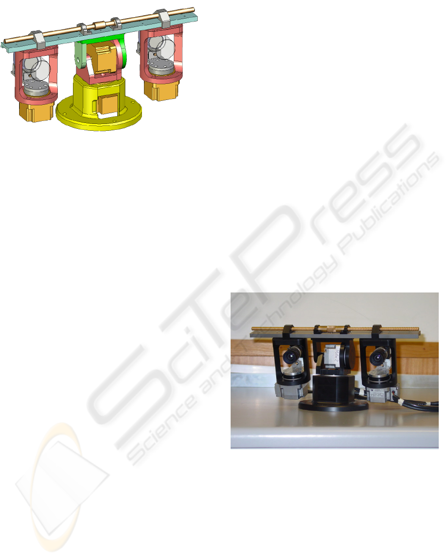
Figure 1: A CAD drawing of POPEYE.
that are designed for interaction with humans in mind,
like the Mertz robot (Aryananda and Weber, 2004),
which was given a friendlier appearance with a mask
that resembles a human face. A stereo head that is de-
signed for precision and robustness much like ours, is
CeDAR (Cable Drive Active vision Robot) (Truong
et al., 2000). Further work that has dealt with con-
trol aspects as well as design of active vision robots
are (Yamato, 1999; Andersen et al., 1996; Grosso and
Tistarelli, 1995). The problems that affect a binoc-
ular active vision head are analysed in (Gasteratos
and Sandini, 2002). Here, the authors conclude that
systems perform optimally when they are initialized
such that the two cameras are perfectly aligned and
perpendicular to the baseline. Small variations in the
vergence angle or small horizontal deviations of the
principal point influence the ability to extract 3D in-
formation from stereo images dramatically. This in-
sight guided the development of the POPEYE system.
3 THE POPEYE STEREO HEAD
The stereo robot head was designed to mimic the ba-
sic abilities of the human head. The human visual sys-
tem has nine degrees of freedom, they are the mechan-
ical degrees of the neck: pan, tilt and swing; the op-
tical degrees of the eyes: focus and aperture; and the
mechanical degrees of the eyes: tilt, pan and swing.
However neck pan and tilt are tightly coupled with
eye pan and tilt. This effectievely reduces the degrees
of freedom to those needed to fixate a point in 3D
space. More details on the human visual system can
be found in (Carpenter, 1988).
The POPEYE robot has a Helmholtz configura-
tion (Helmoltz, 1925) (tilt axis shared by both eyes),
and consists of four rotational degrees of freedom:
neck pan, neck tilt and individual eye pan. Two more
manually adjustable degrees of freedom or configu-
ration parameters are available, namely the baseline
between the eyes and the translational distance of the
optical center of each eye to the tilt axis. Thus, in
terms of degrees of freedom, POPEYE is comparable
to a human head.
One main advantage of this robot head is that the
robot eyes are not affected by translations other than
the neck-pan movements. This is possible because of
the location of the camera centers, which allows pure
rotation along the eye axis. Thereby calculation of
new fixation targets is greatly simplified. The head
features two "eye" slots for cameras and two "ear"
slots for microphones (not used in the present study)
at places that roughly match the location of human
eyes and ears.
3.1 Hardware
In order to simulate the performances of the human
visual system, there is a requirement for large accel-
eration, low friction, high repeatability and minimal
transmission errors. As also seen in POPEYE, these
are some of the primary characteristics of systems that
use motors and feedback devices mounted directly to
the axes of motion.
Figure 2: A picture of the robot POPEYE.
The dynamic performance and accuracy are
achieved with harmonic drive AC motors. With the
harmonic drive gear-boxes transmission compliance
and backlash, which can cause inaccuracy and oscil-
lations, are almost eliminated. Harmonic drive gears
have several advantages:
• They operate with zero backlash which makes the
robot suitable for smooth pursuit movements;
• They are available with positioning accuracy of
better than one minute of arc and repeatability
within a few seconds of arc;
VISAPP 2009 - International Conference on Computer Vision Theory and Applications
430
• They have high torque capacity since power is
transmitted through multiple tooth engagement.
Harmonic Drive gearing offers output torque ca-
pacity equal to conventional gears twice the size
and three times the weight.
The dynamic properties of the robot are summarized
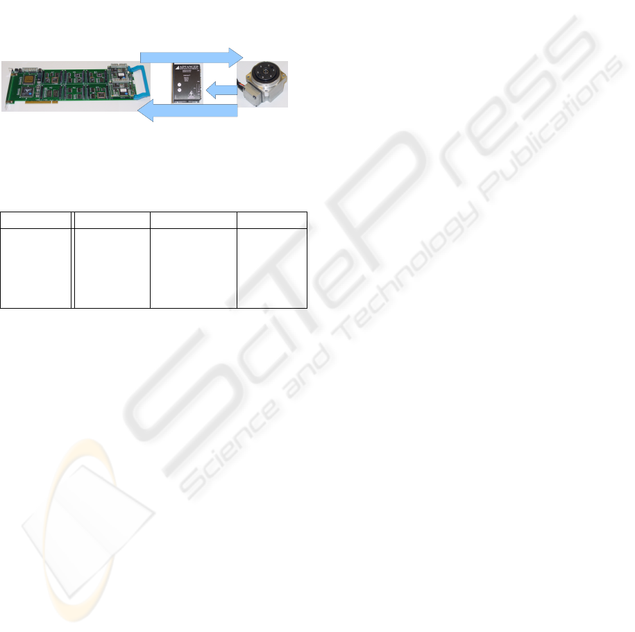
in Table 1. The connection of a standard PC to the
motors of POPEYE is schematized in Figure 3. The
control signal originates from a controller board that
is connected to the PCI bus of the PC and is ampli-
fied in a servo drive before reaching the motors. The
motors send feedback to the encoders.
Controller Board
DCX-PCI300(PMC)
Brushless AC Motor
Harmonic Drive
Servo Drive
(Amplifier)
Encoder readings
Hall
Control Signals
Figure 3: The robot control hardware, the control board, the
servo drive and the motors.
Table 1: Dynamic characteristics of the POPEYE robot.
Precision Range Velocity
Neck Pan (2.5E
−6
)
◦
[−110
◦
,110
◦
] ∼ 8.4
◦
/s
Neck Tilt (2.5E
−6
)
◦
[−35
◦
,35
◦
] 10
◦
/s
Eye pan (4.16E
−6
)
◦
[−45
◦
,55
◦
] ∼ 18.7
◦
/s
Baseline — [165mm, —
340mm]
The cameras used in the robot are Flea2 cam-
eras from PointGrey. They are firewire color cameras
based on a Sony 1/3” progressive scan CCD that can
capture images with resolutions up to 1024 × 768 at
30Hz. The system can optionally be used with lenses
of different focal lengths.
3.2 Calibrating the Robot
In order to guarantee 3D fixation (i.e. having the prin-
cipal point of both cameras pointing to the same point
in space), calibration of both the cameras and the ge-
ometry of the robot must be performed with good ac-
curacy. We use the algorithm described in (Zhang,
1999) to calibrate the intrinsic and extrinsic parame-
ters of the cameras as well as radial distortion (the tan-
gential distortion is negligible). Having pure rotations
in the eye axes simplifies the image formation geome-
try. Pure rotation is important to implement distance-
independent saccade algorithms and is essential for
algorithms that assume that the relationship between
motion space and motion in joint space may be esti-
mated without knowledge of the target distance.
In order to have pure rotations of the camera in the
eye axes, the camera centers have to be adjusted by
displacing the camera along the optical axis. To per-
form this adjustment of the camera center two meth-
ods are proposed:
• Parallax based method. Consider two objects at
different depths. If after a rotation of the eye,
the relative positions of the corresponding images
change, then the motion had a translational com-
ponent. To test this effect, we placed a pattern
with black vertical lines on white background on
the wall. To create the parallax effect we placed
between the camera and the pattern a transparent
acrylic sheet with just one thinner vertical black
line. The thickness of this line was adjusted to
create the illusion that it is an extension of one of
the lines of the pattern on the wall. This adjust-
ment has been done by hand, and an edge detector
was used to confirm the straightness of the result-
ing line. If after the rotation the straightness is not
the same, this means that we don’t have pure ro-
tation and the position of the center of projection
must be adjusted by displacing the lens camera
body along the optical center.
• Homography based. The homography resulting
from a pure rotation has the same eigenvalues (up
to scale) as the rotation matrix (Hartley and Zis-
serman, 2004). Consequently the angle of rotation
between views may be computed directly from the
phase of the complex eigenvalues of the homog-
raphy matrix. This method can be used to vali-
date the results from the previous one, although
empirical experience demonstrated that it is very
sensitive to noise.
When using active cameras in a multi-camera con-
figuration, it is convenient and often essential to be
able to define a fiduciary frame in which the cameras
are aligned with each other. The most natural choice,
in the case of a stereo robot head, is for the cam-
eras to be pointing straight ahead such that they are
i) parallel, ii) perperpendicular to the elevation axis
and iii) perpendicular to the pan axis, i.e. horizon-
tal. This fiducial aligned frame could be realized us-
ing special mechanical and/or optical devices, but can
also be achieved automatically, a process called self-
alignment. This self alignment was achieved with an
implementation of the methods described in (Knight
and Reid, 2006).
3.3 Kinematics and Fixation
To move the robot head to a new fixation target, cor-
rect motor commands have to be generated that con-
trol neck tilt, neck pan and eye vergence. If a fixa-
tion target is only defined by one 2D point in each
ATTENTION MODELS FOR VERGENCE MOVEMENTS BASED ON THE JAMF FRAMEWORK AND THE
POPEYE ROBOT
431
camera, the corresponding 3D point has to be recon-
structed. Given the intrinsics of the cameras and the
corresponding points in both images the coordinates
of the 3D point can be triangulated by intersecting the
rays defined in each camera by the focal point and
the corresponding pixel. Since in most cases the rays
do not intersect, the fixation point is computed as the
middle point of the line segment that minimizes the
distance between the two rays.
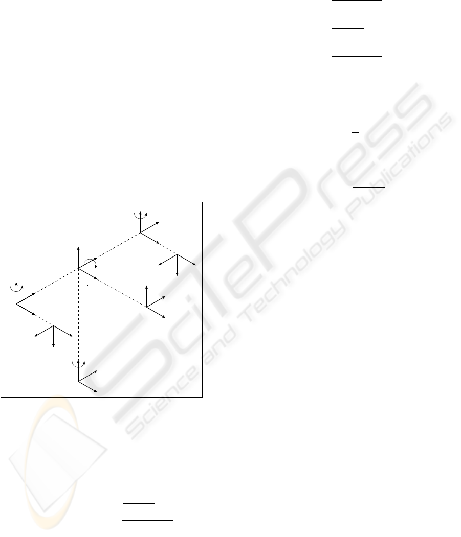
3.3.1 Direct Kinematics
We make the following approximations in order to
simplify the computation:
• The center of the head is the cyclopean eye, so
D = 0
• The eyes rotatation is pure (no translation from the
original frame is involved) so ∆l = 0 and ∆r = 0
• the fixation is symmetric, so θ
l
= −θ
r
.
θ
p
θ
t
θ
r
θ
l
W
c
W
l
W
r
W
b
W
n
W
cam
l
W
f
RIGHT EYE
LEFT EYE
TILT
PAN
∆
r
∆
l
X
X
X
X
X
X
Y
Y
Y
Y
Y
Y
Z
ZX
Z
Z
Z
Y
Z
Z
r
D
W
cam
r
B
B
Figure 4: The kinematic geometry of POPEYE.
The following transformation (T ) relates the pose
of the fixation frame {W
f
} to the base frame{W
b
},
where
W
b
R
W
f
is a rotation component:
W
b
T
W
f
=
Bsin(θ
p
)cos(θ
t
)
tan(θ
r
)
W
b
R
W
f
−Bsin(θ
t
)
tan(θ
r
)
+ D
Bcos(θ
p
)cos(θ
t
)
tan(θ
r
)
0 0 0 1
(1)
3.3.2 Inverse Kinematics
Given a point in 3d world space it is possible to have
the robot fixate the 3d point using the equations that
follow. The position of the fixation point in the frame
{b} :
x
b
=
Bsin(θ
p
)cos(θ
t
)
tan(θ
r
)
y
b
=
−Bsin(θ
t
)
tan(θ
r
)
z
b
=
Bcos(θ
p
)cos(θ
t
)
tan(θ
r
)
(2)
Equations for the eyes, θ
r
(right eye), θ
l
(left eye), θ
p
(neck pan) and θ
t
(neck tilt):
θ
p
= tan
−1
x
b
z
b
θ
t
= tan
−1
−
y
b
q
x
2
b
+z
2
b
!
θ
r
= tan
−1
Bcos(θ
t
)
q
(x
2
b
+z
2
b
)
!
θ
l
= −θ
r
(3)
4 ATTENTIONAL ROBOT
CONTROL
One of the main purposes of POPEYE is to study
and develop different models of attention in a re-
alistic embodied setting. Compared to competing
approaches we emphasize a universal setup to de-
velop and study attention models. Therefore we com-
bine POPEYE with the graphical attention modelling
framework JAMF which is able to express many ex-
isting saliency models. For a more detailed treatment
of the framework see (Steger et al., 2008). In the fol-
lowing we provide a rough sketch of the framework
and argue why it is well suited for attentional robot
control.
4.1 The JAMF Attention Modeling
Framework
JAMF is an open source application that allows rapid
prototyping and development of attention models.
Models are represented as directed graphs that have
functional units, called components, as nodes. Within
such a graph, information is passed in the form of
matrices from one unit to the next along connecting
edges. Thus, each unit processes the output of its pre-
decessors. Executing a graph means to traverse it in
a breadth- first manner and to perform the function of
each node. When a full pass is done, we speak of one
VISAPP 2009 - International Conference on Computer Vision Theory and Applications
432
iteration of the graph. To handle non-static environ-
ments (e.g. video camera input) the graph is iterated
multiple times, e.g. processing one frame per itera-
tion.
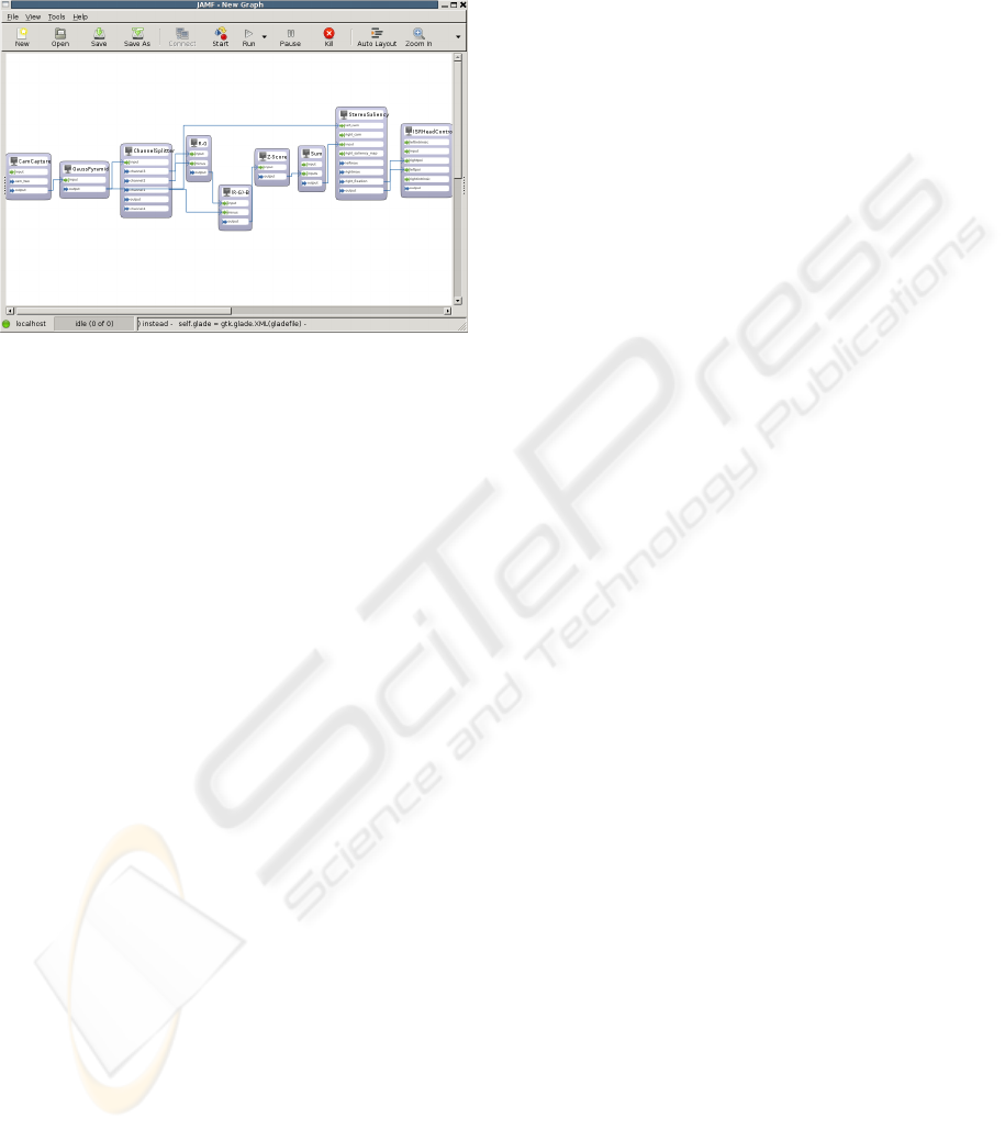
Figure 5: A screenshot of the JAMF Client. The boxes
on the white canvas symbolize functional units, the arrows
show the flow of information. The graph depicted, receives
input from POPEYE’s cameras, down-samples them and
splits the RGB image into individual channels. With this
information, a saliency map is computed that contains only
information about red colors (S = R − G − B). The result
is fed into the "StereoSaliency" component that takes the
maximum of the saliency map. For clarity, only processing
for one camera is shown. In the full version, the "Stere-
oSaliency" component receives input from the second cam-
era as well. It then compares found maxima in both im-
ages by computing a sum of squared differences and out-
puts two points which are used by the "ISR Head Control"
component to generate motor commands that fixate the cor-
responding 3D point.
At its core, JAMF uses a client-server architecture.
The JAMF client is used for development of models
and control of running simulations. New models can
be developed by dragging available components to a
drawing canvas (see Figure 5) where connections that
specify the flow of information can be drawn. The
client also controls execution of the developed mod-
els. Besides starting, stopping or pausing running
models, it provides means to feed input and param-
eters into the graph and to introspect and visualize
intermediate results. If components expose parame-
ters (e.g. window size), these can be modified by the
client as well.
The server instantiates models into running simu-
lations. It receives a graph from the client, translates
it into equivalent C code, compiles and links the sim-
ulation against the component repository and a con-
troller application. Due to the use of directed graphs
as a representation, the server can automatically ex-
ploit the structure of the graph to parallelize inde-
pendent branches. This allows to utilize all cores on
multi-core processors. Once the simulation is started,
the client connects to the controller application via
TCP/IP. This communication channel allows to:
• Start, stop and pause simulations
• Set components’ parameters
• Request output of components
• Send input to components
A component within the JAMF framework is an al-
gorithm, which is wrapped into a C++ class that pro-
vides access to input, output and parameters. This
can conveniently be achieved by extending JAMF’s
base component class and obeying a naming conven-
tion (e.g. input, output, getter and setter methods start
with input_, out put_, get_ and set_ respectively). In-
puts and outputs are OpenCV matrices. The existing
component base makes heavy use of this highly op-
timized computer vision library, which is encouraged
for new components as well.
JAMF is well suited for the task of attentional
robot control for several reasons. By using directed
graphs as model representation, JAMF captures the
structure of most existing saliency models. They
usually consist of a set of discrete processing stages
(e.g. feature extraction, conspicuity map computa-
tion, conspicuity map combination, top-down inte-
gration), where each stage depends on the output of
its predecessors. Another important aspect for robot
control is computational efficiency. JAMF can reach
high performance due to several strategies. The use
of native C code and OpenCV for component devel-
opment generates fast simulations. The graph struc-
ture allows automatic parallelization. Development
of new attention models is eased by the graphical
client and the standard component repository which
contains many building blocks of common attention
models. JAMF separates model from implementation
such that technical details are "hidden" by the graph-
ical client. Therefore, model developers do not nec-
essarily need knowledge of specific implementation
details. A functional description, as provided in the
built-in user documentation, for each component suf-
fices.
4.2 JAMF-POPEYE Interface
To use POPEYE within JAMF attention models we
use the following setup (see Figure 6). A new com-
ponent was developed that, given two corresponding
points, fixates the robot head on this point (see 3.3).
For this, POPEYE has to be connected to the host that
runs the JAMF server, as this component uses low
level API routines and hardware. Existing attention
ATTENTION MODELS FOR VERGENCE MOVEMENTS BASED ON THE JAMF FRAMEWORK AND THE
POPEYE ROBOT
433

Figure 6: The JAMF / POPEYE setup. Camera output is
fed into the attention model. The model generates a new
target point which is transduced into motor commands by
the actuator component.
models can be extended to control POPEYE by in-
cluding and feeding fixation targets into this compo-
nent. Execution and control of the simulation can then
be carried out remotely from the machine that runs the
JAMF client using a TCP/IP connection.
5 USE CASE
Having described the software and hardware setup
in previous chapters, it is fruitful to see some ex-
emplary implementations of attention models. The
general task is, given two input images, to generate
a new fixation target for the robot head. A simple
approach is to find interesting points in each image
separately, which corresponds to computation of two
saliency maps. The "ISR Head Control" component
can then triangulate a 3D point from the two points
and generate motor commands that move the robot
head to fixate this point. Obviously, the triangulation
is only meaningful when the two 2D coordinates point
to the same point in 3D space. To check this, we com-
pute the sum of squared differences in a patch around
the 2D coordinates. A fixation target is only accepted
when the difference is sufficiently small. Insofar, the
attention model can be treated as a black box as long
as it outputs two saliency maps (see Figure 6 for a
graphical depiction).
For an easy example consider an attention model
that is tuned to red colors as the only interesting fea-
ture. Figure 5 shows a JAMF graph that models this.
Mathematically, simple saliency models can be ex-
pressed in the following way:
Given an input image I we compute feature ma-
trices, named F
f eaturename
. In the example mentioned
above the "redness" feature F
red
is obtained by sub-
tracting the green and blue color channel G(I),B(I)
from the red color channel R(I).
F
red
(I) = R(I) − G(I) − B(I) (4)
The resulting matrix F is normalized by transforming
its values into z-values by subtracting the mean
¯
F and
dividing by the standard deviation σ
F
. Note that the
parameter t specifies the number of frames that are
used to estimate the mean and variance.
Z(F,t) =
F −
¯
F
t
σ
F,t
(5)
Using equations 4 and 5, we compute a weighted sum
of z-scored feature values as final saliency map S. The
sum is formed over the set of different feature maps
(Γ), where each is weighted by a scalar θ
γ
. In the ex-
ample above the set of feature matrices just contains
the redness feature Γ = {F
red
} and hence no weight is
necessary.
S(I,t) =
∑
γ∈Γ
θ
γ
∗ Z(F
γ
(I),t) (6)
The most interesting point in an image is defined
as the location of the maximum in the saliency map
S(I,t).
p
d
= argmax(S(I
d
,t)) (7)
Where argmax returns the position of the maximum
in a matrix. Note that this has to be done on both
input images (d ∈ {l,r}).
The implementation of the "redness" model in
JAMF is straightforward. First, new camera input
from both cameras is obtained by the “CamCapture”
component. Each camera frame is processed inde-
pendently in its own processing stream. To speed
up performance, two "GaussianPyramid" components
downscale the camera images delievered by "Cam-
Capture" to a resolution of 320x240 pixels. To extract
the "red" feature, two "ChannelSplitter" components
split the input images into their RGB color channels.
Two "Sub" components for each camera can then sub-
tract the green and blue channel from the red channel.
The resulting feature maps are then normalized by the
“ZTransformation” component and summed with the
“Add” component for each camera individually. At
this point, the information of both cameras is fused
by the "StereoSaliency" component. It computes the
sum of squared differences in a patch surrounding the
most salient points in each input image. If the SSD
falls below a threshold, the “ISRHead Control” com-
ponent triangulates a new 3D fixation target and mo-
tor commands are send to the robot to fixate the new
target. This simple demonstration serves as a proof of
concept. Naturally, considering only the color "red"
is not too interesting.
VISAPP 2009 - International Conference on Computer Vision Theory and Applications
434
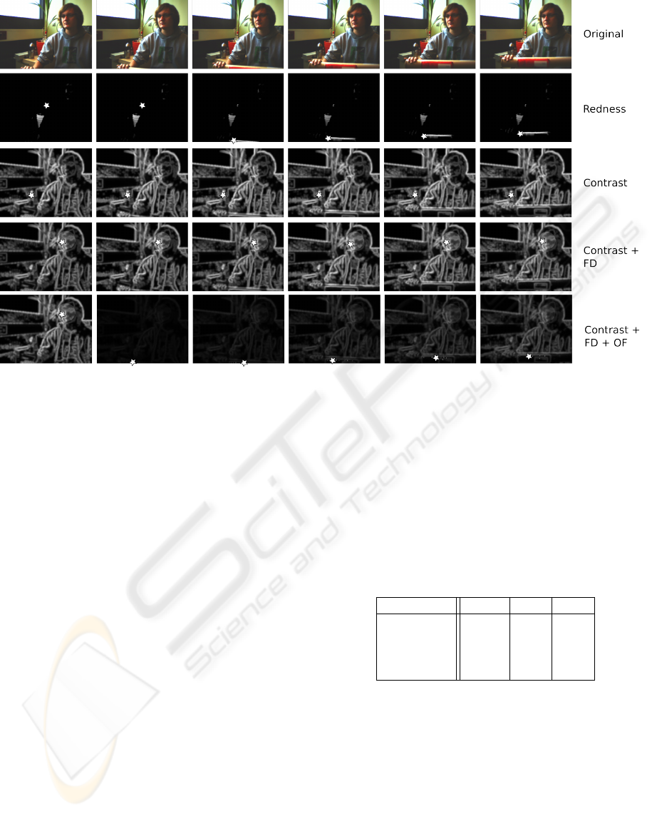
Figure 7: Exemplary results from all four implemented saliency models. The first row gives the original, unprocessed movie
frame. In the following rows fixation targets (maxima) are indicated using a star. Saliency maps are shown for models using
1) red as salient feature, 2) contrast measurements, 3) contrast measurements plus face detection, 4) contrasts, face detection
and optical flow as features. The influence of the time dependent z-score normalization can be seen in the last row. Sudden
onset of movement in the 4th frame boosts the influence of the optical flow feature, which returns to baseline after several
frames.
It is easy to extend this model with different fea-
tures. Adding new features such as optical flow
or face detection can be accomplished by simply
adding the respective components to the model ("Op-
ticalFlow", "FaceDetect") which can be done with a
few clicks. They are connected in the same way as the
"redness" feature. They receive input from the gaus-
sian pyramid and their output is normalized by the
"ZTransformation" component. The z-score normal-
ization ensures that different features can be summed
without risking that one feature alone drives the fi-
nal saliency map. All in all we have implemented
four different saliency models that differ in the fea-
tures they use:
1. Model #1 uses only the color red as feature as de-
scribed above
2. Model #2 uses red-green, blue-yellow and lumi-
nance contrasts
3. Model #3 extends model #2 with face detection
4. Model #4 extends model #3 with optical flow
This scheme demonstrates how easy it is to test
new attention models in this setup. Figure 7 shows the
resulting saliency map from the four different models
Table 2: Performance of models 2-4. The models were
evaluated on a 2x Dual-Core AMD Opteron Processor (2.2
GHz) with 4GB Ram. All values in frames per second.
“Single” refers to graphs where only monocular input is
processed, the number of feature extraction components is
thus half compared to “double” graphs. “MP” refers to eval-
uation with automatic parallelization.
Model: #2 #3 #4
Single 17.2 9.6 7.8
MP single 29.3 13.3 11.4
Double 12.8 5.5 4.9
MP double 24.31 11.5 9.9
mentioned above. Notably, the generated fixation pat-
terns can be saved along with the visual input to eval-
uate the behavior of the POPEYE robot. This allows
to compare computational models with psychophysi-
cal experiments. We have refrained from carrying out
such experiments, as our main focus is to provide a
setup in which these comparisons are possible.
An important aspect for the comparison of embod-
ied attention models with human behavioral data is
the processing speed. Table 2 shows a summary of
how many frames per second can be processed with
this setup. (Salthouse and Ellis, 1980) report that the
ATTENTION MODELS FOR VERGENCE MOVEMENTS BASED ON THE JAMF FRAMEWORK AND THE
POPEYE ROBOT
435

minimum duration of a fixation is in the order of 200-
500ms, which suggests that even the most complex
model is fast enough to simulate natural fixation be-
havior (with about 10fps). This also demonstrates the
automatic parallelization abilities of JAMF. Depend-
ing on the number of components, complexity of each
component and the graph structure a speed-up of fac-
tor two can be reached without manual adjustments.
6 CONCLUSIONS
In this work, we introduce a novel setup to study and
develop attention models on POPEYE, a human in-
spired stereo vision robot head. POPEYE allows to
study attention models in a more realistic, embodied,
three dimensional setting. The geometric properties
of the head make it easy to control. The robot can
be controlled by JAMF, a framework to develop and
test attention models in a graphical fashion. The com-
bination of both allows to easily implement attention
models that drive the robot’s behavior. Its capabilites
to evaluate different attention models in an embodied
setting make it a prime candidate for comparing atten-
tion models to psychophysical data. Because design
and technical realization are hidden behind a graphi-
cal abstraction layer it can be used by researchers that
do not have a specific computer science background.
Within the setup, attention models are represented as
directed graphs that can easliy be shared with other
research groups.
The head is prepared to use stereo auditory inputs
as well. One straightforward way to incorporate audi-
tory information into the existing saliency models is
to use estimated locations of auditory input sources as
a 2D bias field that modifies saliency values greatest
at points closest to the source (Quigley et al., 2008).
Such a feature can be treated in the same manner as
all other features in the shown saliency models.
However, there are some problems that still need
to be adressed. So far, a human operator is required
for calibration of the robot before a simulation ses-
sion. Furthermore we have not optimized the speed
of POPEYE to match human saccade-behavior, thus
the speed of movement might not match that of hu-
mans.
The models presented in this work are rather sim-
ple, but show the capabilities of the setup. There are
several open issues with these models. For instance,
practical experience has shown that using a threshold
for the sum of squared differences to compare the two
salient points is not optimal. It is very sensitive to
noise and does not work on rather uniform areas. The
choice of features in the current models is also very
limited and can be improved. One of the most ob-
vious issues that needs improvement is probably the
integration of overt and covert visual attention. Ein-
häuser et al. investigate eye-in-head movements and
head-in-world movements and suggest that both have
distinct contributions for gaze allocation (Einhäuser
et al., 2008).
Future work to improve our models will build on
some of the models presented in the literature. In
(Choi et al., 2006) a biologically motivated vergence
control method for an active stereo vision system that
mimics human-like stereo visual selective attention
is proposed. They compute a gist of the scene that
can later be used in localization. In our case the gist
could be used for online parameterization of the fea-
ture extraction stage. Thereby, the model can be tuned
to different environments (e.g. indoor and outdoor
scenes). Furthermore a depth feature could be inte-
grated into our model. The process of retrieving 3D
information from stereo saliency maps is described
in (Conradt et al., 2002). A vergence control stereo
system using retinal optical flow disparity and target
depth velocity is described in (Batista et al., 2000).
A saliency map model considering depth informa-
tion as a feature is described in (Ouerhani and Hugli,
2000), although the range data was retrieved using
a laser range finder. In this work we have pursued
a strategy where one saliency map is computed for
every camera. Henkel has proposed a depth estima-
tion algorithm that is able to compute a “cyclopean”
view of a stereo scene (Henkel, 1998). This allows
to resolve several issues that are problematic when
using binocular saliency maps: a cyclopean view is
not concerned with occluded image areas ((Bruce and
Tsotsos, 2005), (Zitnick and Kanade, 1999)) and can
speed up the saliency map computation as only one
map has to be computed. Furthermore, it can aid the
triangulation of a 3D fixation target by giving a depth
estimate. We have put forwarded an integrated hard-
and software system for simulation of visual atten-
tion that has to be seen as a step into the direction of
studying models of attention in a more realistic and
embodied way.
ACKNOWLEDGEMENTS
We gratefully acknowledge the support by IST-
027268-POP (Perception On Purpose).
VISAPP 2009 - International Conference on Computer Vision Theory and Applications
436

REFERENCES
Andersen, C. S., Andersen, C. S., Crowley, J. L., D, P. P., D,
P. P., and Perram, J. (1996). A framework for control
of a camera head. Technical report.
Aryananda, L. and Weber, J. (2004). Mertz: a quest for a ro-
bust and scalable active vision humanoid head robot.
Humanoid Robots, 2004 4th IEEE/RAS International
Conference on, 2:513–532.
Batista, J., Dias, J., Araújo, H., and Almeida, A. (1995).
The isr multi-degrees-of-freedom active vision robot
head: design and calibration. In M2VIP’95–Second
International Conference on Mechatronics and Ma-
chine Vision in Practice, Hong–Kong.
Batista, J., Peixoto, P., and Araújo, H. (2000). A focusing-
by-vergence system controlled by retinal motion dis-
parity. In ICRA, pages 3209–3214.
Bruce, N. and Tsotsos, J. (2005). An attentional framework
for stereo vision. Computer and Robot Vision, 2005.
Proceedings. The 2nd Canadian Conference on, pages
88–95.
Carpenter, H. (1988). Movements of the Eyes. London Pion
Limited, second edition edition.
Choi, S.-B., Jung, B.-S., Ban, S.-W., Niitsuma, H., and Lee,
M. (2006). Biologically motivated vergence control
system using human-like selective attention model.
Neurocomputing, 69(4-6):537–558.
Conradt, J., Simon, P., Pescatore, M., and Verschure, P.
(2002). Saliency maps operating on stereo images
detect landmarks and their distance. In ICANN ’02:
Proceedings of the International Conference on Arti-
ficial Neural Networks, pages 795–800, London, UK.
Springer-Verlag.
Einhäuser, W., Schumann, F., Bardins, S., Bartl, K., Böning,
G., Schneider, E., and König, P. (2007). Human eye-
head co-ordination in natural exploration. Network:
Computation in Neural Systems, 18(3):267–297.
Einhäuser, W., Schumann, F., Vockeroth, J., Bartl, K., M.,
C., J., H., Schneider, E., and König, P. (2008). Dis-
tinct Roles for Eye for Eye and Head Movements in
Selecting Salient Image Parts During Natural Explo-
ration (in press). Ann. N.Y. Acad. Sci.
Fellenz, W. A. and Hartmann, G. (2002). A modular low-
cost active vision head.
Gasteratos, A. and Sandini, G. (2002). Factors affecting
the accuracy of an active vision head. In SETN ’02:
Proceedings of the Second Hellenic Conference on AI,
pages 413–422, London, UK. Springer-Verlag.
Grosso, E. and Tistarelli, M. (1995). Active/dynamic stereo
vision. IEEE Transactions on Pattern Analysis and
Machine Intelligence, 17(9):868–879.
Hartley, R. and Zisserman, A. (2004). Multiple View Geom-
etry in Computer Vision. Cambridge University Press.
Helmoltz, H. (1925). Treatize on physiological optics.
Dover.
Henkel, R. (1998). A Simple and Fast Neural Network Ap-
proach to Stereovision. Advances in Neural Informa-
tion Processing Systems, pages 808–814.
Itti, L. and Koch, C. (2001). Computational modelling
of visual attention. Nature Reviews Neuroscience,
2(3):194–204.
Jansen, L., Onat, S., and König, P. (2008). Free viewing of
natural images: The influence of disparity. Journal of
Vision (in press).
Knight, J. and Reid, I. (2006). Automated alignment of
robotic pan-tilt camera units using vision. Interna-
tional Journal of Computer Vision, 68(3):219–237.
Knudsen, E. (2007). Fundamental Components of Atten-
tion. Annual Review of Neuroscience, 30:57.
Ouerhani, N. and Hugli, H. (2000). Computing visual atten-
tion from scene depth. In ICPR ’00: Proceedings of
the International Conference on Pattern Recognition,
page 1375, Washington, DC, USA. IEEE Computer
Society.
Quigley, C., Onat, S., Harding, S., Cooke, M., and König,
P. (2008). Audio-visual integration during overt visual
attention. Journal of Vision (in press).
Salthouse, T. and Ellis, C. (1980). Determinants of eye-
fixation duration. Am J Psychol, 93(2):207–34.
Steger, J., Wilming, N., Wolfsteller, F., Höning, N., and
König, P. (2008). The jamf attention modelling frame-
work. In WAPCV 2008, Santorini, Greece.
Truong, H., Abdallah, S., Rougeaux, S., and Zelinsky, E.
(2000). A novel mechanism for stereo active vision. In
In Proc. Australian Conference on Robotics and Au-
tomation. ARAA.
Yamato, J. (1999). A layered control system for stereo vi-
sion head with vergence. Systems, Man, and Cyber-
netics, 1999. IEEE SMC ’99 Conference Proceedings.
1999 IEEE International Conference on, 2:836–841
vol.2.
Zhang, Z. (1999). Flexible Camera Calibration By View-
ing a Plane From Unknown Orientations. In Inter-
national Conference on Computer Vision (ICCV’99),
pages 666–673, Corfu, Greece.
Zitnick, C. and Kanade, T. (1999). Cooperative algorithm
for stereo matching and occlusion detection. Tech-
nical Report CMU-RI-TR-99-35, Robotics Institute,
Carnegie Mellon University, Pittsburgh, PA.
ATTENTION MODELS FOR VERGENCE MOVEMENTS BASED ON THE JAMF FRAMEWORK AND THE
POPEYE ROBOT
437
