
CORRECTION OF ACOUSTIC LENS ERROR IN SPATIAL
COMPOUNDING OF ULTRASONIC DIAGNOSTIC IMAGES
Myoung H. Choi
Dept. of Electrical and Electronic Eng., Kangwon National University, 192-1 Hyoja- dong, Chuncheon, Korea
Keywords: Spatial compounding, Image registration, Lens error.
Abstract: Spatial compounding has been used in ultrasonic imaging for suppressing speckle noise. The technique
generally involves electronically steering the ultrasonic beams. The steering angle of the ultrasonic beam is
distorted by the acoustic lens structure of the probe that is used to focus the beam mechanically. These
errors introduced by the lens structure cause misalignment of the ultrasonic images received at different
steering angles, and consequently results in the blurred image after spatial compounding. In this paper, a
solution is proposed that corrects the lens error by using image registration. The lens error was compensated
by registering the wire target images before spatial compounding. An efficient registration algorithm was
developed to compute the transformation matrix required for the registration. The images were registered by
the transformation matrix before spatial compounding.
1 INTRODUCTION
Ultrasonic images show a characteristic granular
structure commonly known as speckle (Burckhardt,
1978, Wells and Halliwell, 1981). Speckle is one of
the fundamental problems of ultrasound imaging,
and it is a cause of major limitation on image
quality. Speckle in ultrasonic images arises from the
presence of closely spaced and randomly distributed
microscopic scatterers (Ahbott, 1979, Wagner,
1983). The coherence of the ultrasound sources and
the interference pattern caused by these tiny targets
result in fluctuations in the amplitude of the echo
called speckle. Although speckle noise carries some
information about the nature of the imaging object,
the speckle reduces the detection capability of
ultrasonic imaging systems, and makes it difficult to
identify specific target regions on the image.
Spatial compounding has been used to reduce
speckle brightness variations. The compounded
image is formed by, for example, averaging the
component images that have been acquired by
steering ultrasound beams in several different
directions. In the component images, the structural
targets show consistently strong echoes while
speckles show random variations. Consequently, the
structural targets in compounded images are
enhanced and variations in the soft tissues due to
speckle noise are averaged out (Shankar, 1986). As a
result, image contrast is improved, and electronic
noise is reduced and artifacts such as shadowing and
reverberation are suppressed. Examples in (Entrekin,
2001, Huber, 2002) show improvements in
visualization of breast lesions. These results indicate
that spatial compounding can enhance the
delineation of the boundaries and internal structure
of lesions. The improvement, however, is usually
gained at the price of spatial resolution. The
misalignment of the legions caused by aberration
and the loss of spatial resolution can degrade the
effectiveness of spatial compounding (Krücker,
2002, Meuwly, 2003).
Steering of electronic beam is accomplished
electronically by controlling the excitation of the
individual elements in the ultrasonic transducer
array. One of the errors introduced by the electronic
steering of the ultrasonic beam is caused by the
acoustic lens structure that is used to mechanically
focus the ultrasonic beam, such as the thickness and
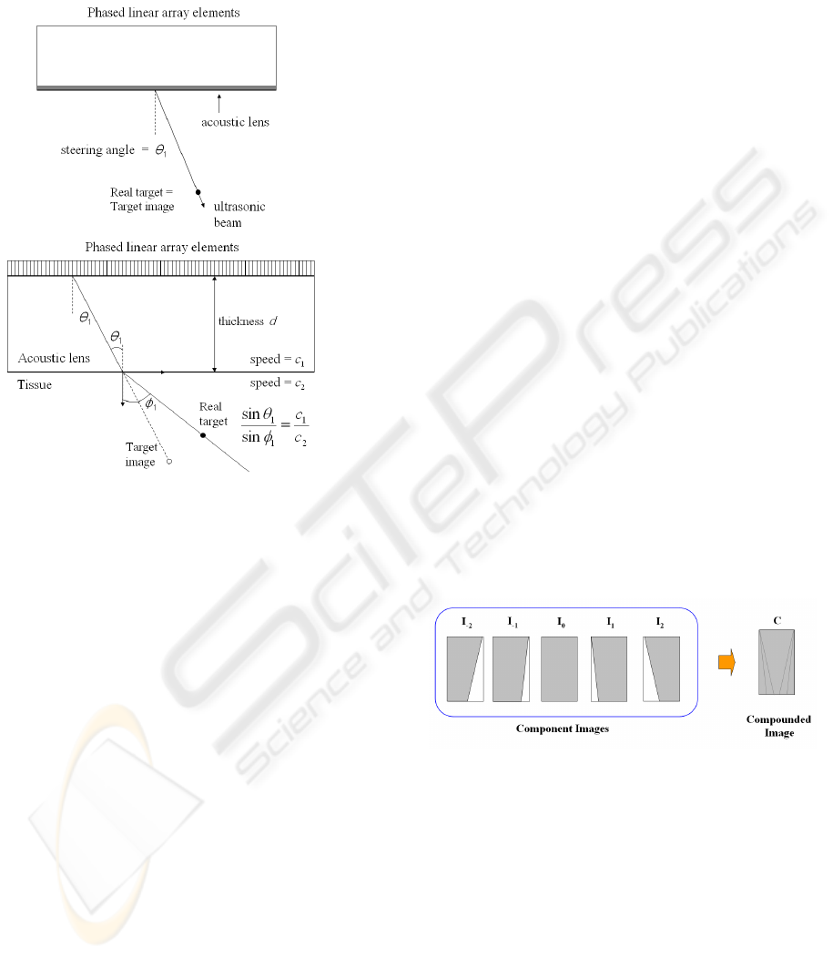
acoustic speed of the lens. In Figure 1, ideal case is
compared with the real case. In an ideal case, the
ultrasound echo data reflected off the target is
received along a simple straight line. In a real
situation, the ultrasound echo data path is changed at
the interface between the lens and the tissue. The
steering angle is changed from
1
θ
to
1
φ
by the ratio
of the acoustic speed of the lens and the tissue.
These errors introduced by the lens structure cause
235
Choi M. (2009).
CORRECTION OF ACOUSTIC LENS ERROR IN SPATIAL COMPOUNDING OF ULTRASONIC DIAGNOSTIC IMAGES.
In Proceedings of the International Conference on Biomedical Electronics and Devices, pages 235-238
DOI: 10.5220/0001548302350238
Copyright
c
SciTePress
misalignment of the ultrasonic images received at
different steering angles, and consequently results in
the blurred image during the spatial compounding.
(a) Ideal
case
(b) Real
case
Figure 1: Acoustic lens error in the steering of ultrasound
beam.
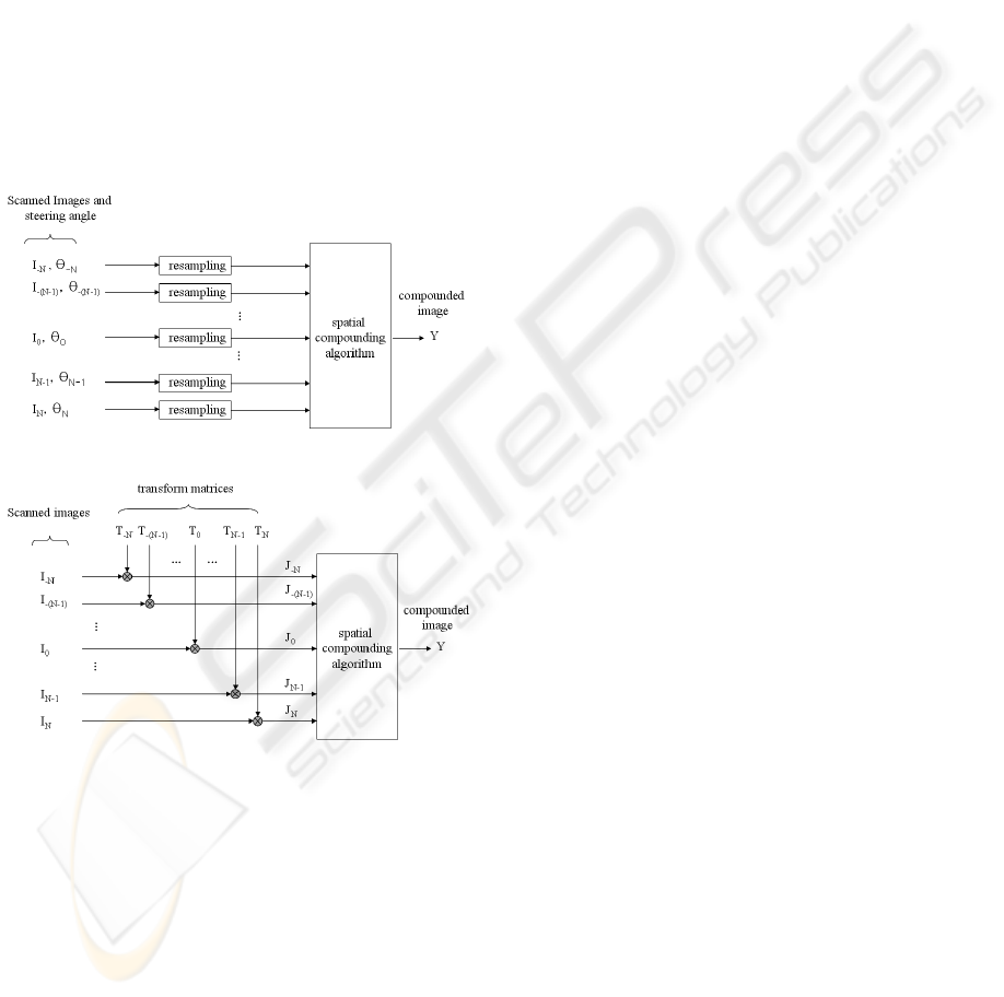
The conventional solution to correct the errors
introduced by the lens structure involve manual fine
tuning of the lens thickness and the steering angles.
These parameters are used in the resampling process
which geometrically transforms the image data from
the probe coordinates to the patient coordinates as
shown in Figure 3(a). In ultrasound imaging systems,
this kind of manual fine tuning can be difficult and
time consuming as many different kinds of probes
are used interchangeably for different diagnostic
applications.
In this work, a systematic solution is proposed
that corrects the lens error by using image
registration. The lens error was compensated by
registering the wire target images before spatial
compounding. An efficient registration algorithm
was developed to compute the transformation matrix
required for the registration. The images were
registered by the transformation matrix before
spatial compounding.
2 SPATIAL COMPOUNDING
WITH LENS ERROR
CORRECTION
A typical spatial compounding scheme that uses 5
component image frames from a linear probe to
generate a compounded image is described in Figure
2. Each of the component images I
k
corresponds to a
steering angle of k
Δθ
, where
Δθ
is the incremental
angle and I
0x
is the image corresponding to the zero
rotation angle. Various methods were proposed to
compute the compounded image from the
consecutive frames which include linear averaging,
median, mean-excluding- minimum, root mean
square, etc (Wilhjelm,2004). In this work, a simple
linear averaging scheme was used.
Let I
i
, i= -N,…0,…N, denote the component
images that will be used in the spatial compounding.
The center image I
0
undergoes no rotation and thus
is free from the influence of the lens errors. Hence,
the center image I
0
is used as the reference frame
with respect to which all other images will be
transformed for registration. Let T
i
, i= -N,…0,…N,
denote the geometric transformation matrices that
transforms images I
i
such that J
i
= T
i
I
i
will be the
image registered with respect to the reference frame.
The alignment errors between the component images
are removed by the registration process. The
registered images J
i
can be used to produce the
compounded image by a spatial compounding
algorithm as shown in Figure 3.
Figure 2: Concept of Spatial Compounding.
The transformation matrix T
i
that registers the
component image I
i
with respect to the reference
image I
0
is computed from the images of a wire
phantom. The wire phantom images are converted to
binary images by using a suitable gray level
threshold. Threshold value is selected to generate
clear binary images of wire targets. For each image
I
k
, position vector of the wire targets u
kj
= [x
kj
, z
kj
]
T
,
j=1,…M, are obtained by computing the center of
gravity of the wire targets, where M is the number of
wire targets, x
kj
and z
kj
are the x and z coordinates of
the position vector u
kj
.The position vector of the
BIODEVICES 2009 - International Conference on Biomedical Electronics and Devices
236
same wire target in the reference image I
0
is denoted
as u
0j
= [x
0j
, z
0j
]
T
, j=1,…M.
Let the position vectors be expressed in
homogeneous coordinates (Fu,1987). Let H
k
, k= -
N,…0,…N, denote the 4x4 homogeneous
transformation matrices that transform u
kj
to u
0j
.
Then we can write
⎥
⎥
⎥
⎥
⎦
⎤
⎢
⎢
⎢
⎢
⎣
⎡
=
⎥
⎥
⎥
⎥
⎦
⎤
⎢
⎢
⎢
⎢
⎣
⎡
1
0
1
0
0
0
kj
kj
k
j
j
z
x
H
z
x
, j=1,…, M (1)
⎥
⎥
⎥
⎥
⎥
⎦
⎤
⎢
⎢
⎢
⎢
⎢
⎣
⎡
=
1000
34333231
24232221
14131211
hhhh
hhhh
hhhh
H
kkkk
kkkk
kkkk
k
(a) Conventional spatial compounding.
(b) Spatial compounding with image registration.
Figure 3: Comparison of spatial compounding schemes.
We can remove the y component of the equation and
rewrite (1) as below.
⎥
⎥
⎥
⎦
⎤
⎢
⎢
⎢
⎣
⎡
⎥
⎥
⎥
⎦
⎤
⎢
⎢
⎢
⎣
⎡
=
⎥
⎥
⎥
⎦
⎤
⎢
⎢
⎢
⎣
⎡
11001
343331
141311
0
0
kj
kj
kkk
kkk
j
j
z
x
hhh
hhh
z
x
, j=1,…, M (2)
This equation can be expressed
⎥
⎥
⎥
⎦
⎤
⎢
⎢
⎢
⎣
⎡
=
⎥
⎥
⎥
⎦
⎤
⎢
⎢
⎢
⎣
⎡
11
0
0
kj
kj
kj
j
z
x
Tz
x
, j=1,…, M (3)
⎥
⎥
⎥
⎦
⎤
⎢
⎢
⎢
⎣
⎡
=
100
343331
141311
hhh
hhh
T
kkk
kkk
k
Here, T
k
is the transformation matrix that registers
the wire targets of I
k
with the reference image I
0
.
Since T
k
applies to all the wire targets in the image
I
k
,
⎥
⎥
⎥
⎦
⎤
⎢
⎢
⎢
⎣
⎡
=
⎥
⎥
⎥
⎦
⎤
⎢
⎢
⎢
⎣
⎡
111111
21
21
00201
00201
L
L
L
L
L
L
kMkk
kMkk
kM
M
zzz
xxx
Tzzz
xxx
(4)
Let the equation (4) be written in a simplified form
as
kk
UTU =
0
(5)
Then, the transformation matrix T
k
can be computed
by
1
0
)(
−
=
T
kk
T
kk
UUUUT
(6)
3 EXPERIMENTAL RESULTS
The images were denoted as I
i
, i=-3,…,0,…3, and
hence images corresponding to 7 different view
angles were used in the spatial compounding. Seven
consecutive images were used in the compounding
computation, each of 5232 x 256 RF sample data,
and compounded images are shown after scan
conversion into a 640 x 480 BW data.
The binary images of I
i
were obtained by selecting
a threshold. Six wire targets were used in the
computation. The wire target positions u
kj
= [x
kj
,
z
kj
]
T
, j=1,…6, k= -3, …, 0, …, 3 were obtained by
computing the center of gravity of the binary images
of wire targets. The transformation matrix T
k
were
computed using (6), and used to register the
component images I
i
to the reference image I
0
. The
registered images are denoted by that J
k
= T
k
I
k
. The
position error between the wire target of the k-th
image and that of the reference image were
computed before and after the registration and their
magnitudes are shown in Figure 4. Before the
registration, the position error increases with the
rotation angle, error increasing to over 110 pixels
(RF data) in I
-3
and I
3
. After the registration, the
position errors were reduced to less than or equal to
one pixel with the exception of I
3
where the
maximum error magnitude was three pixels.
CORRECTION OF ACOUSTIC LENS ERROR IN SPATIAL COMPOUNDING OF ULTRASONIC DIAGNOSTIC
IMAGES
237
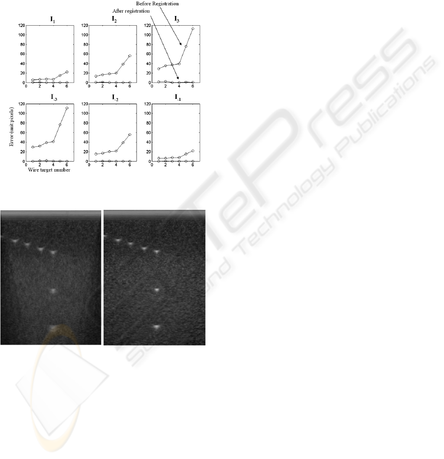
The compounded image obtained by the
conventional spatial compounding scheme is shown
in Figure 5(a) and contain geometric errors caused
by the lens error and the result of compounding
these misaligned images is the blurry compounded
image. The proposed spatial compounding with
image registration was applied to the same image
and the result is shown in Figure 5(b).
Figure 4: Registration error of wire targets before and after
the registration.
(a) no lens error compensation (b) Proposed method
Figure 5: Spatial compounding results.
4 CONCLUSIONS
A lens error correction method for spatial
compounding is proposed that uses image
registration. The lens error was compensated by
registering the wire target images before spatial
compounding. An efficient registration algorithm
was developed to compute the transformation matrix
required for the registration. The images were
registered by the transformation matrix before
spatial compounding. It was shown that the
registration error that causes the blurring of the
spatially compounded images can be removed
effectively.
REFERENCES
C. B. Burckhardt, 1978. “Speckle in ultrasound B scans,”
IEEE Trans. Sonics Ultrason., SU-25, 1-6.
J. G. Ahbott and F. L. Thurstone, 1979. “Acoustic speckle:
Theory and experimental analysis,” Ultrason.
Imaging, 1, 303-324.
P. N. T. Wells and M. Halliwell, 1981. “Speckle in
ultrasonic imaging,” Ultrason., 19, 225-229,.
R. F. Wagner. S. W. Smith, J. M. Sandrik and H. Lopez,
1983. “Statistics of speckle in ultrasound B scans,”
IEEE Trans. Sonics Ultrason., SU-30, 156-163,.
D. P. Shattuck and O. T. von Ramm, 1982. “Compound
scanning with a phased array,” Ultrason. Imaging,
4(2), 93–107.
M. O’Donnell and S. D. Silverstein, 1988. “Optimum
displacement for compound image generation in
medical ultrasound,” IEEE Trans. Ultrason.,
Ferroelect., Freq. Contr., 35(4), 470–476.
S. D. Silverstein and M. O’Donnell, 1987. “Speckle
reduction using correlated mixed-integration
techniques,” in Proc. SPIE 768 Pattern Recognition
and Acoust. Imaging, 168–172.
G. E. Trahey, S. W. Smith, and O. T. von Ramm, 1986.
“Speckle pattern correlation with lateral aperture
translation: Experimental results and implications for
spatial compounding,” IEEE Trans. Ultrason.,
Ferroelect., Freq. Contr., 33(3), 257–264.
P. M. Shankar, 1986. "Speckle Reduction in Ultrasound
B-Scans Using Weighted Averaging in Spatial
Compounding", IEEE Trans. On Ultrasonics,
Ferroelectrics, and Frequency Control, Vol. UFFC-33(6).
R. R. Entrekin, B. A. Porter, H. H. Sillesen, A. D. Wong,
P. L. Cooperberg, and C. H. Fix, 2001. “Real-time
spatial compound imaging: Application to breast,
vascular, and musculoskeletal ultrasound,” Semin.
Ultrasound CT MR, 22(1), 50–64.
S. Huber, M. Wagner, M. Medl, and H. Czembirek, 2002.
“Real-time spatial compound imaging in breast
ultrasound,” Ultrasound Med. Biol., 28(2), 155–163.
J. F. Krücker, G. L. LeCarpentier, J. B. Fowlkes, and P. L.
Carson, 2002. “Rapid elastic image registration for 3-
D ultrasound,” IEEE Trans. Med. Imag., 21(11),
1384–1394.
J.-Y. Meuwly, J.-P. Thiran, and F. Gudinchet, 2003.
“Application of adaptive image processing technique
to real-time spatial compound ultrasound imaging
improves image quality,” Invest. Radiol., 38(5), 257–262.
Wilhjelm, J. E., Jensen M. S., Jespersen S.K., Sahl B.,
Falk E. 2004. "Visual and Quantitative Evaluation of
Selected Image Combination Schemes in Ultrasound
Spatial Compound Scanning," IEEE Trans. on
Medical Imaging, 23(2), 181-190.
Fu, Gonzales, and Lee, 1987. Robotics: Control, Sensing,
Vision and Intelligence, McGraw-Hill.
BIODEVICES 2009 - International Conference on Biomedical Electronics and Devices
238
