
DESIGN ACTIVITIES FOR SUPPORTING THE EVOLUTION OF
SERVICE-ORIENTED ARCHITECTURE
Dionisis X. Adamopoulos
Department of Technology Education & Digital Systems, University of Piraeus, Greece
Keywords: Service design, new telecommunications services, service engineering, service creation, UML.
Abstract: The advent of deregulation combined with new opportunities opened by advances in telecommunications
technologies has significantly changed the paradigm of telecommunications services, leading to a dramatic
increase in the number and type of services that telecommunication companies can offer. Building new
advanced multimedia telecommunications services in a distributed and heterogeneous environment is very
difficult, unless there is a methodology to support the entire service development process in a structured and
systematic manner, and assist and constrain service designers and developers by setting out goals and
providing specific means to achieve these goals. Therefore, in this paper, after a brief presentation of a
proposed service creation methodology, its service design phase is examined in detail focusing on the
essential activities and artifacts. In this process, the exploitation of important service engineering techniques
and UML modelling principles is especially considered. Finally, alternative and complementary approaches
for service design are highlighted and a validation attempt is briefly outlined.
1 INTRODUCTION
The creation of new advanced telecommunications
services (telematic services) within an open network
environment with increased intelligence and
programmable features is a highly complex activity.
This complexity stems not only from the technical
nature of the tasks involved, but also from the
number of the participating actors and the variety in
their roles, concerns, and skills. Therefore, There is
a need to support the complex service creation
process in order to ensure that resulting services
actually perform as planned and as required by
customers and service providers. A methodology is
an important part of such an attempt, as it provides a
systematic and structured base for the flexible and
efficient management of the development of
telecommunications services.
In this paper, in order to structure and control the
service development process from requirements
capture and analysis to service implementation, to
reduce the inherent complexity, and to ensure the
thorough compatibility among the many involved
tasks, a service creation methodology, conformant to
the open service architectural framework specified
by the Telecommunications Information Networking
Architecture Consortium (TINA-C) (Berndt,
2003)(TINA-C, 2003), is proposed. Special
emphasis is given to the service design phase of the
methodology as it provides valuable answers to
several important service engineering matters and
thus facilitates the transition to a
telecommunications environment where many
different (enhanced) services are offered by a multi-
plicity of service providers to several categories of
customers within an open market.
2 THE PROPOSED SERVICE
CREATION METHODOLOGY
Telecommunications operators need to master the
complexity of service software, because of the
highly diversified market demands, and
consequently, because of the necessity to quickly
and economically develop and introduce a broad
range of new services. To achieve such an
ambitious, yet strategic to the telecommunications
operator’s goal, a service creation methodology
based on the rich conceptual model of TINA-C is
proposed (Adamopoulos, 2003).
A high-level or macro-level view of the proposed
service creation methodology can be seen in Figure
1. The proposed service development process is
53
X. Adamopoulos D. (2008).
DESIGN ACTIVITIES FOR SUPPORTING THE EVOLUTION OF SERVICE-ORIENTED ARCHITECTURE.
In Proceedings of the Third International Conference on Software and Data Technologies - SE/GSDCA/MUSE, pages 53-59
DOI: 10.5220/0001884800530059
Copyright
c
SciTePress
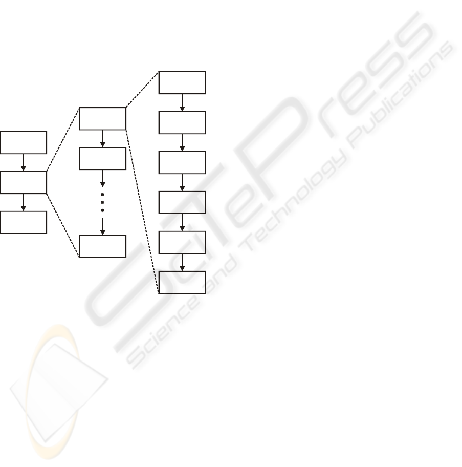
based on an iterative and incremental, use case
driven approach. An iterative service creation life
cycle is adopted, which is based on successive
enlargement and refinement of a telematic service
through multiple service development cycles within
each one the telematic service grows as it is enriched
with new functions. More specifically, after the
requirements capture and analysis phase, service
development proceeds in a service formation phase,
through a series of service development cycles. Each
cycle tackles a relatively small set of service
requirements, proceeding through service analysis,
service design, service implementation and
validation, and service testing. The telematic service
grows incrementally as each cycle is completed.
Requirements
Capture and
Analysis
Service
Development
Cycle 1
Requirements
Refinement
Service
Formation
Service
Optimisation
Service
Development
Cycle 2
Service
Development
Cycle n
Artifacts
Synchronisation
Service Analysis
Service Design
Service
Implementation
Service Validation
and Testing
Figure 1: Overview of the proposed service creation
methodology.
According to Figure 1 the main phases of the
proposed methodology are the following:
• Requirements capture and analysis phase: It iden-
tifies the telematic service requirements (together
with a number of roles), and presents them in a
structured way.
• Service analysis phase: It describes the semantics
of the problem domain that the telematic service is
designed for. Thus, it identifies the objects that
compose a service (information service objects),
their types, and their relationships.
• Service design phase: It produces the design
specifications of the telematic service under
examination. Computational modelling is taking
place in this phase and thus the service is
described in terms of TINA-C computational
objects interacting with each other.
• Service implementation phase: In this phase the
pieces of the service software (computational
objects) are defined and implemented in an object-
oriented programming language (e.g. C++, Java),
inside a TINA-C compliant Distributed Processing
Environment (DPE).
• Service validation and testing phase: It subjects
the implemented telematic service to a variety of
tests in order to ensure its correct and reliable
operation.
• Service optimisation phase: It examines thor-
oughly the service code in order to improve its
performance in the target DPE, and thus prepare
the telematic service for a successful deployment.
As can be seen from Figure 1, the proposed
methodology is conceptually consistent with the
viewpoint separation as advocated by TINA-C in
accordance with the Reference Model for Open
Distributed Processing (RM-ODP), and uses the
service life-cycle of Fig. 1 as a roadmap. It has to be
stressed that the proposed methodology does not
imply a waterfall model in which each activity is
done once for the entire set of service requirements.
Furthermore, graphical and textual notations are
proposed for almost all phases to improve the
readability of the related results and ensure a level of
formalism sufficient to prevent any ambiguity. In the
following paragraphs the service design phase of the
proposed methodology is examined focusing on its
essential characteristics and artifacts. In the
following paragraphs the service design phase of the
proposed methodology is examined focusing on its
essential characteristics and artifacts.
3 THE SERVICE DESIGN PHASE
During this phase the service developer defines the
behaviour of the service concepts (service
Information Objects, IOs) that were identified in the
service analysis phase and structures the telematic
service in terms of interacting service computational
objects (service components or service objects),
which are distributable, multiple interface service
objects. They are the units of encapsulation and
programming. While service IOs mainly explain
how a service is defined, service Computational
Objects (COs) reveal what actions have to be
performed in order to execute the service. Therefore,
the output of this phase is (mainly) the dynamic
ICSOFT 2008 - International Conference on Software and Data Technologies
54
view of the internal structure of the telematic
service.
Service
Development
Cycle 1
Requirements
Refinement
Service
Development
Cycle 2
Service
Development
Cycle n
Artifacts
Synchronisation
Service Analysis
Service Design
Service
Implementation
Service Validation
and Testing
Define Service
Interaction Diagrams
Define Real Use Cases
3
Define User Interface Aspects
Define Service
Architecture Layers
1
Define Service
Design Class Diagrams
Define Database Schema
2
1: varied order
2: if applicable
3: optional
Notes
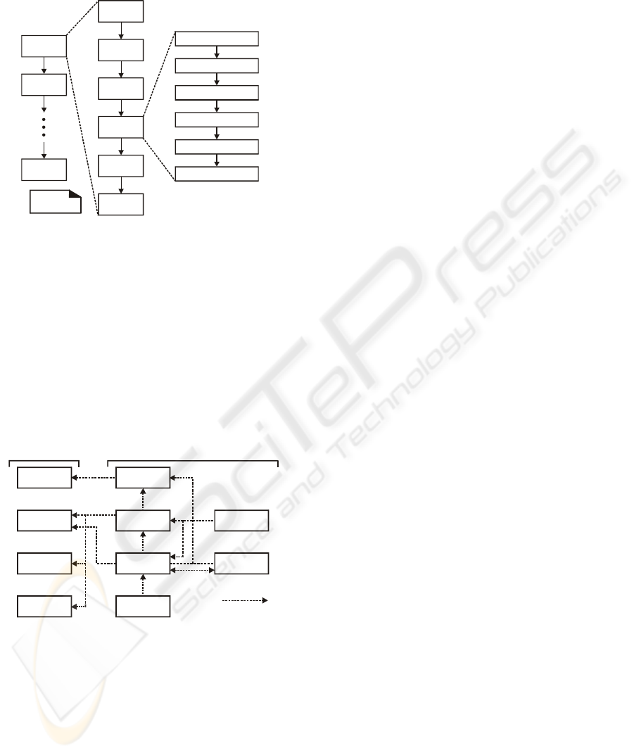
Figure 2: Service design phase activities.
The activities of the service design phase are
depicted in Figure 2. The linear order that may be
inferred from this figure is not strictly the case, as
some artifacts may be made in parallel (e.g. the
service interaction diagrams and the service design
class diagram). The dependencies between the arti-
facts produced during the service design phase and
the way that they depend on some of the service
analysis phase artefacts can be seen in Figure 3. The
most important activities of the service design phase
are examined in the following sections.
Service
Interaction
Diagrams
dependency on
Use Cases
(real)
Service Design
Class Diagrams
Service
Conceptual
Model
ODL Specifications
Service State
Diagrams
Service
Operation
Contracts
Use Cases
(expanded,
essential)
Database
Schema
Service Architecture
Package Diagrams
Service Analysis Phase Artifacts Service Design Phase Artifacts
Figure 3: Service design phase artifact dependencies.
Initially, important characteristics of the user
interface of the service are defined by examining the
related prototype (produced during service analysis)
and taking into account the feedback from the users
of the service. The adherence to specific GUI
standards and user interface design principles is also
decided in this activity.
The application of the Model-View separation
principle, according to which the service logic
should not be bound to a particular user interface, is
proposed. More specifically, it is usually desirable
that there is no direct coupling from service objects
to user interface objects, because the user interface
objects are related to a particular telematic service,
while (ideally) the service objects may be reused in
new telematic services or attached to a new
interface. The application of the Model-View
separation principle in the service design phase
supports the creation of cohesive service design
phase artifacts that focus on the service domain
processes and not on the satisfaction of user
interface requirements, allows the separate
development of the service logic from the necessary
user interface, and minimises the impact upon the
service logic layer from changes of the requirements
regarding the user interface (Constantine,
2005)(Larman, 2006).
After identifying the service COs, by taking into
account the service conceptual model(s) and the
TINA-C service architecture, a (separate) service
interaction diagram is created for each service
operation under development in the current service
development cycle. Service interaction diagrams
illustrate how service objects communicate in order
to fulfil the service requirements. More specifically,
initially the expanded use cases suggested the
service events which were explicitly shown in
service sequence diagrams, then an initial best guess
at the effect of these service events was described in
service operation contracts, and finally the identified
service events represent messages that initiate
service interaction diagrams, which illustrate how
service objects interact via messages to fulfil the
required tasks.
Therefore, service interaction diagrams reveal
choices in assigning responsibilities to service
objects. The responsibility assignment decisions are
reflected in the messages that are sent to different
service objects. Responsibilities are related to the
obligations that a service object has in terms of its
behaviour. In the service implementation phase,
methods will be implemented to fulfil responsibili-
ties or alternatively responsibilities will be
implemented using methods, which either act alone
or collaborate with the methods of other service
objects.
UML defines two kinds of interaction diagrams,
either of which can be used to express similar or
even identical message interactions; namely collabo-
ration diagrams, which illustrate object interactions
in a graph or network format, and sequence
diagrams, which illustrate interactions in a kind of
fence format (Evits, 2006). The use of collaboration
diagrams for the expression of service interaction
DESIGN ACTIVITIES FOR SUPPORTING THE EVOLUTION OF SERVICE-ORIENTED ARCHITECTURE
55

diagrams is preferred over the use of sequence
diagrams, because collaboration diagrams are
characterised by expressiveness, an ability to convey
more contextual information (such as the kind of
visibility between service objects), and a relative
spatial economy.
Nevertheless, either notation can express similar
constructs. What is really important is that service
interaction diagrams is one of the most significant
artifacts created during both service analysis and
service design, because the skilful assignment of
responsibilities to service objects and the design of
collaborations between them are two of the most
critical (for the satisfaction of the service require-
ments and thus for the successful realisation of a
service) and unavoidable tasks (which also require
the application of design skill) that have to be
performed during service creation (Larman, 2006).
This activity of the service design phase consists
mainly from the following steps:
Step 1:
Identify the service COs.
During this step, the service IOs depicted in the
service conceptual models (main and ancillary) that
were created in the service analysis phase are
considered as potential candidates for service COs.
In many cases, service IOs are mapped to one
corresponding service CO encapsulating the
information defined by the service IO and providing
an operational interface to access that information.
However, the mapping between service IOs and
service COs is not necessarily one to one.
Furthermore, the existence of a relationship between
service IOs, either provides a good rationale for
encapsulating them together in the same service CO
or indicates the need for a binding between
interfaces of their corresponding service COs
(Declan, 2000)(Demestichas, 2004).
This mapping process is significantly simplified
by adopting the use of the generic (access session,
service session, and communication session related)
service COs, proposed by the TINA-C service archi-
tecture (TINA-C, 2003), in terms of their identified
functionality and not in terms of specific interfaces /
feature sets. Furthermore, by taking into account the
related documentation that is available by the TINA-
C, Table 1 and Table 2 are constructed and reveal
the way that the functionality of the TINA-C service
COs was devised.
Regarding these two tables, it has to be noted
that when a session concept is mapped to a TINA-C
service CO, then the service CO supports the
functionality and state of the session, and controls
the resources which are part of the session. If a
session concept is mapped to several TINA-C
service COs, then each of them supports part of the
functionality and state, and controls some of the
resources of the session. When a service IO is
mapped to a TINA-C service CO then the informa-
tion represented by the service IO is contained
within the CO, which may also provide access to
that information to other TINA-C service COs.
Table 1: Mapping between service concepts and TINA-C
access session related COs.
Service IOs / Session Concepts TINA-C Service
Components
Access Session (AS) with
User-Provider Roles
PA and UA
Access Session (AS) with
Peer-to-Peer Roles
PeerA and PeerA
User Domain Access Session
(UD_AS)
PA
Provider Domain Access
Session (PD_AS)
UA
Peer Domain Access Session
(PeerD_AS)
PeerA
User Profile with User-
Provider Roles
UA
User Profile with Peer-to-Peer
Roles
PeerA
Contract with User-Provider
Roles
PA and UA
Contract with Peer-to-Peer
Roles
PeerA and PeerA
Considering Table 1 and Table 2, together with
the service requirements and any other artifact
produced by the proposed methodology so far, the
service IOs depicted in the service conceptual
models (main and ancillary) that were created in the
service analysis phase are mapped to the appropriate
service COs. As a result of this process a table is
constructed listing all the service COs that will be
used in the service design phase and their corre-
sponding service IO(s).
Considering the previous discussion, the
following actions take place during this step:
• Consider the generic TINA-C service COs and
their mapping to service IOs (Table 1 and Table
2).
• Relate each service IO in the service conceptual
models (main and ancillary) to the appropriate
service CO.
• Construct a table regarding the service COs that
will be used during the service design phase.
ICSOFT 2008 - International Conference on Software and Data Technologies
56
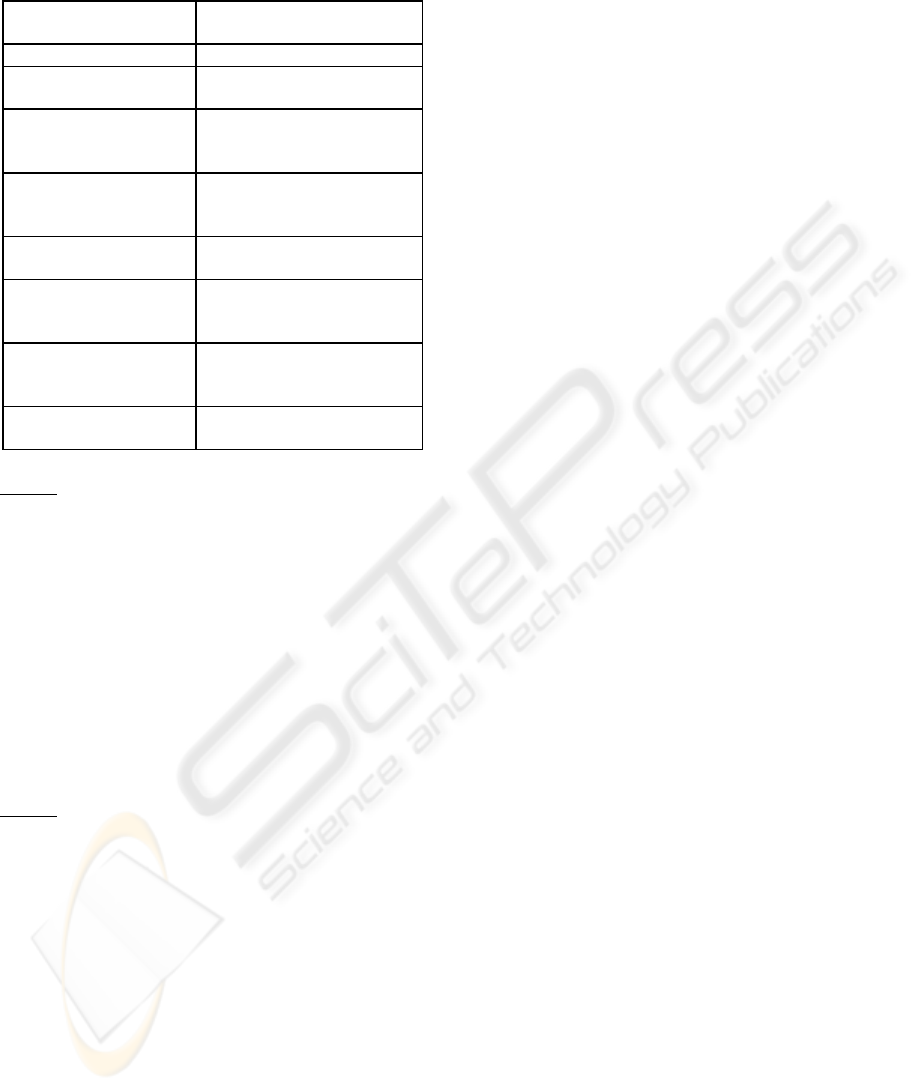
Table 2: Mapping between service concepts and TINA-C
service session related COs.
Service IOs / Session
Concepts
TINA-C Service
Components
Service Session (SS) ss-UAP, USM, SSM
Usage Service Session
(USS)
ss-UAP, USM
User Domain Usage
Service Session
(UD_USS)
ss-UAP
Provider Domain
Usage Service Session
(PD_USS)
USM
Provider Service
Session (PSS)
SSM
Composer Domain
Usage Service Session
(CompD_USS)
CompUSM
Peer Domain Usage
Service Session
(PeerD_USS)
PeerUSM
Service Session Graph
Information Model IOs
ss-UAP, USM, SSM,
CompUSM, PeerUSM
Step 2: Consider the generic TINA-C service scenar-
ios and select the most appropriate.
After identifying the service COs and before
proceeding to the construction of the service
interaction diagrams, the computational views of a
number of generic TINA-C service scenarios,
deduced by the computational modelling guidelines
of TINA-C (TINA-C, 2003), should be considered.
These are useful for improving structure and general
comprehension throughout the service design phase,
and for offering to the service developer(s) a generic
pattern of thought, compatible with fundamental
TINA-C concepts, that he / she could use / consider
when designing the service interaction diagrams.
Step 3:
Form the service interaction diagrams.
A telematic service is composed of a set of
service COs interacting with each other via
messages with the objective to complete the required
service operations. The service operation contracts
present an initial best guess at responsibilities and
post conditions for the service operations. Service
interaction diagrams illustrate the proposed design
solution (in terms of service COs) that satisfies
theses responsibilities and post conditions, and
therefore the corresponding service operations.
A service interaction diagram in the form of a
UML collaboration diagram is created for each one
of the service operations that were identified in the
service analysis phase. The objective is to fulfil the
responsibilities and the post-conditions of the corre-
sponding service operation contracts, recognising
however that their accuracy should be questioned.
As was explained in step 1 of this activity the
service COs that participate in the service interaction
diagrams are drawn from the service conceptual
model(s). Therefore, the links between them are ac-
tually instances of the associations present in the ser-
vice conceptual model(s), represent connection paths
between service object instances, and indicate that
some form of navigation between the instances is
possible. More specifically, in order for a service
object to send a message to another service object it
must have visibility to it. Thus, it is important to en-
sure that the necessary (attribute, parameter, locally
declared or global) visibility is present in order to
support the required message interaction (Jacobson,
2006)(Larman, 2006).
Finally, all telematic services have a “Start Up”
use case and some initial service operation related to
the starting up of the telematic service. Therefore,
there should also be a “Start Up” service interaction
diagram, which is proposed to be created last.
Although the “Start Up” service operation is the
earliest one to execute, the development of its
service interaction diagram should be delayed until
after all other service operations have been
considered. This ensures that significant information
has been discovered concerning what initialisation
activities are required to support the “Start-Up”
service operation interaction diagram. The way that
a telematic service starts and initialises is affected by
related concepts / guidelines in the TINA-C service
architecture (e.g. it is assumed that the IA must be
present at the provider domain), and is dependent
upon the DPE, the programming language, and the
operating system that is being used.
Another important artifact created during service
design is the service design class diagram, which
illustrates the specifications for the software classes
of a telematic service using a strict and very infor-
mative notation. More specifically, from the service
interaction diagrams the service designer identifies
the software classes (service classes) that participate
in the software realisation of the telematic service
under examination, together with their methods, and
from the service conceptual model(s) the service
designer adds detail to the service class definitions.
A service design class diagram typically includes
/ illustrates service classes, their attributes and
methods, attribute type information, navigability,
and associations and dependencies between service
classes. In practice, service design class diagrams
and service interaction diagrams are usually created
in parallel. Furthermore, in contrast with a service
DESIGN ACTIVITIES FOR SUPPORTING THE EVOLUTION OF SERVICE-ORIENTED ARCHITECTURE
57
conceptual model, a service design class diagram
shows definitions of software entities (service
components), rather than real-world concepts.
The following steps are proposed for the creation
of a service design class diagram:
Step 1:
Identify the service classes by analysing the
service interaction diagrams.
Step 2:
Draw all the identified service classes in a
simple service design class diagram.
Step 3:
Duplicate the attributes to the service classes
from the associated concepts in the service
conceptual model(s). All attributes are
assumed to be private by default.
Step 4:
Add method names to the service classes by
analysing the service interaction diagrams.
In general, the set of all messages sent to a
service class X across all service interaction
diagrams indicates the majority of methods
that service class X must define.
Step 5:
Add type information to the attributes, me-
thod parameters, and method return values.
It is only recommended when automatic
processing of the service design class
diagram is anticipated by a specialised
software tool.
Step 6:
Add the (different types of) associations nec-
essary to support the required attribute
visibility. In general, associations are added
in order to satisfy the ongoing memory
needs indicated by the service interaction
diagrams.
Step 7:
Add navigability arrows to the associations
to indicate the direction of attribute
visibility.
Step 8:
Add dependency relationship lines to
indicate non-attribute visibility between
service classes (i.e. parameter, global, or
locally declared visibility).
Step 9:
Split the service design class diagram into
smaller diagrams (if it gets complex).
In the service design phase, Specification and
Description Language (SDL) can be used to describe
the behaviour of a telematic service exploiting the
finite state machine concept. Then, the SDL specifi-
cation will serve also as a basis for validation, simu-
lation and test case generation (Combes, 2005). In
general, for making formal models of telematic
services and being able to reason about these
models, SDL is undoubtedly the notation of choice,
as the tool support for SDL is perhaps the most
advanced of all the formal notations existing today.
However, adopting an SDL-based approach cannot
guarantee that the developed services will be error
free and the value of SDL for service creation
purposes is questioned, as it may introduce
unnecessary complexity in the service design phase.
Furthermore, the application of SDL can be difficult
(or even problematic) in the case of relatively
complex telematic services with many service
objects interacting in non-trivial ways, due to the
problem of state space explosion.
In the service design phase, service COs have a
dominant role. Their interfaces are the result of the
examination of the service IOs and the correspond-
ing information models that they participate in,
which reveal the way that service IOs are related to
each other. This aggregation of interfaces into a ser-
vice CO ensures the semantic understanding that op-
erations at one interface may affect the behaviour of
other interfaces because they may be linked by a
common, underlying information model captured by
the service CO. Therefore, such information models
influence considerably the parameters and the se-
mantics of the operations found on the interfaces of
the service COs.
In order to aid the service development process
TINA-C, proposes and prescribes a set of generic
interfaces for the generic TINA-C service COs.
These interfaces correspond to the interactions that
take place between business administrative domains,
support a particular session role, and are defined by
the appropriate reference point specifications.
TINA-C assembles the proposed interfaces into
feature sets. A feature set is a group of related
interfaces that exposes restricted parts of the
appropriate information model(s) for manipulation
or examination, defines the details of interactions
between service COs, and specifies levels of
functionality inside a service (e.g. basic or
multiparty session control) (TINA-C, 2003).
Use Cases
(real)
1: static
model
2: dynamic
model
Notes
Service
Design
Model
Service State
Diagrams
for Service
COs / Classes
Service Design
Class
Diagrams
Service
Design
Use Case
Model
2
Service
Object
Behaviour
Model
2
Service
Class
Model
1
Service
Architecture
Model
1
Service
Design
Stat e
Model
2
Use Case
Diagram(s)
Service
Interaction
Diagrams
Service
Contracts
for Methods
& Operations
Service
Architecture
Package
Diagrams
Service
Deployment
Diagrams
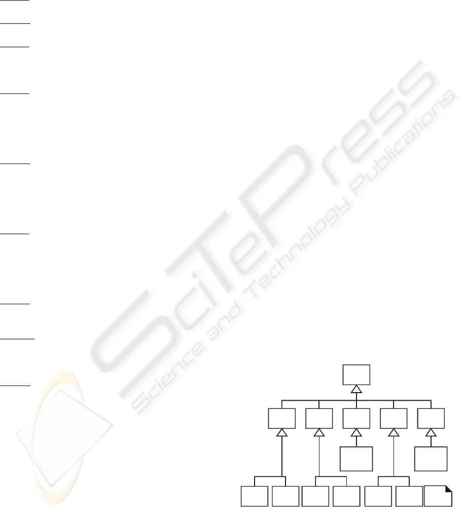
Figure 4: The service design model.
Although not suggested, feature sets can be
applied during the service design phase of the
ICSOFT 2008 - International Conference on Software and Data Technologies
58

proposed methodology. More specifically, service
developers with a TINA-C expertise can critically
use them as an aid (by taking from them whatever
they consider useful) when devising and
constructing the interfaces of the service COs.
However, service developers should not use feature
sets as an excuse for not carefully performing the
requirements capture and analysis phase and the
service analysis phase. Moreover, they should try to
fully integrate them in the service design phase,
improving as much as possible the consistency of
the results of this phase with the results of the
previous phases. Finally, it has to be noted that the
importance of feature sets is expected to increase
when their specification by TINA-C is completed.
The application of feature sets will be especially
useful for telematic services that span multiple
business administrative domains and have to
consider composition and federation issues.
4 CONCLUDING REMARKS
The activities of the service design phase can be
seen in Figure 2. The artifacts that are produced
during this phase can be seen in Figure 3. From the
service design model depicted in Figure 4, is evident
that real use cases are members of the service design
use case model, and service interaction diagrams are
members of the service object behaviour model,
because they describe the behaviour of service COs,
and service design class diagrams compose the
service class model. Furthermore, for reasons of
completeness, the service design model includes
service state diagrams for service COs / classes as
members of the service design state model. Such
diagrams may be useful to summarise the results of a
service design (at the end of the service design
phase) or when the service code is to be produced
with a code generator that will be driven by the state
diagrams.
Finally, it has to be stressed that the proposed
service creation methodology (and thus its service
design phase) was validated and its true practical
value and applicability was ensured as it was applied
to the design and development of a real complex
representative telematic service (a MultiMedia
Conferencing Service for Education and Training,
MMCS-ET). More specifically, a variety of
scenarios were considered involving the support of
session management requirements (session estab-
lishment, modification, suspension, resumption, and
shutdown), interaction requirements (audio / video,
text, and file communication), and collaboration
support requirements (chat facility, file exchange
facility, and voting). Considering all the artifacts
produced in the service design phase, the MMCS-ET
was implemented using Microsoft’s Visual C++ to-
gether with Microsoft’s Distributed Component
Object Model (DCOM) (Adamopoulos, 2002)
(appropriately extended with a high-level API in
order to support continuous media interactions) as a
distributed object-oriented environment.
REFERENCES
Adamopoulos, D.X., Pavlou, G., Papandreou, C.A., 2003.
Advanced Service Creation Using Distributed Object
Technology. In IEEE Communications Magazine, Vol.
40, No. 3, pp. 146-154.
Adamopoulos, D.X., Pavlou, G., Papandreou, C.A., 2002.
Continuous Media Support in the Distributed
Component Object Model. In Computer Communica-
tions, Vol. 25, No. 2, 2002, pp. 169-182.
Berndt, H., Hamada, T., Graubmann, P., 2003. TINA: Its
Achievements and its Future Directions. In IEEE
Communications Surveys & Tutorials, Vol. 3, No. 1.
Combes, P., Renard, B., 2005. Service Validation. In
Computer Networks, Vol. 31, No. 17, pp. 1817-34.
Constantine, L.L., Lockwood, L.A.D., 2005. Software for
Use: A Practical Guide to the Models and Methods of
Usage-Centered Design, Addison-Wesley.
Declan, M., 2000. Adopting Object Oriented Analysis for
Telecommunications Systems Development. In Pro-
ceedings of IS&N ’00, LNCS, Vol. 1238, Springer-
Verlag, pp. 117-125.
Demestichas, P.P., et al, 2004. Issues in Service Creation
for Open Distributed Processing Environments. In
Proceedings of ICC ’04, Vol. 1, pp. 273-279.
Evits, P., 2006. A UML Pattern Language. Macmillan
Technology Series.
Jacobson, I., Booch, J., Rumbaugh, J., 2005. Unified Soft-
ware Development Process. Addison-Wesley.
Larman, C., 2006. Applying UML and Patterns: An
Introduction to Object-Oriented Analysis and Design
and the Unified Process. Prentice Hall.
TINA-C, 2003. Service Architecture. Version 5.0.
DESIGN ACTIVITIES FOR SUPPORTING THE EVOLUTION OF SERVICE-ORIENTED ARCHITECTURE
59
